0.65m短背射天线说明书(SLBS06-8010)
CommScope 7820788G RE 06 天线安装指南说明书

7820788Rev: CMountFeedShield omitted for clarityShieldRadome USX8 shown for illustrative purposes onlyAlways read the entire manual before commencing installationSequence of Antenna AssemblyHX and USX Antennas Antenna Shield7820788GRE 06Bulletin Rev Status Model Version Version Rev Status 2 of 12page Installation InstructionsC RE 02© June, 2018 CommScopeNotice: CommScope disclaims any liability or responsibility for the results of improper or unsafe installation, inspection, maintenance, or removal practices.Aviso: CommScope no acepta ninguna obligación ni responsabilidad como resultado de prácticas incorrectas o peligrosas de instalación, inspección, mantenimiento o retiro. Avis : CommScope décline toute responsabilité pour les conséquences de procédures d’installation, d’inspection, d’entretien ou de retrait incorrectes ou dangereuses. Hinweis: CommScope lehnt jede Haftung oder Verantwortung für Schäden ab, die aufgrund unsachgemäßer Installation, Überprüfung, Wartung oder Demontage auftreten.Atenção: A CommScope abdica do direito de toda responsabilidade pelos resultados de práticas inadequadas e sem segurança de instalação, inspeção,manutenção ou remoção. Avvertenza: CommScope declina eventuali responsabilità derivanti dell’esecuzione di procedure di installazione, ispezione, manutenzione e smontaggio improprie o poco mScope 1100 CommScope Place SE P.O. Box 339, Hickory, NC 28603-0339(828) 324-2200 (800) Customer Service 24 hours North America: +1-800-255-1479 (toll free)Any country: +1-779-435-6500email:**************************************Page 3 of 127820788CONTENTS & INTRODUCTION SECTION 1INSTALLATION INSTRUCTIONSPage 4 of 127820788SAFETY INSTRUCTIONS SECTION 2INSTALLATION INSTRUCTIONSPage 5 of 127820788SAFETY INSTRUCTIONS SECTION 2INSTALLATION INSTRUCTIONSTightening of hardwareIt is recommended that all hardware is tightened to the torques specified in table 3.The integrity of the completed assembly depends on all fasteners being properly tightened.Table 3: Fastener Torque SpecificationsINSTALLATION INSTRUCTIONSSECTION 3COMPONENTS AND TOOLS 7820788Page 6 of 12Tools Required M6M8M10Ring and Open spanner (A/F)10mm 13mm 17mm Torque Wrench 7.7Nm - 38NmSockets (A/F)10mm13mm17mmGeneral ToolboxFastener materialFastener sizeM6M8M10Stainless Steel N-m 7.71938lbf-ft 5.71428GalvanizedN-m --38lbf-ft--28INSTALLATION INSTRUCTIONSSECTION 3COMPONENTS AND TOOLS7820788Page 7 of 12ComponentsSupplied ComponentsINSTALLATION INSTRUCTIONS SECTION 3COMPONENTS AND TOOLS 7820788Page 8 of 12ItemDescription RemarksA1Shield Assembly (part number *-1)A2Shield Assembly (part number *-2)A3Shield Assembly (part number *-3)A4Shield Assembly (part number *-4)B Shield Ring C Joint PlateDShield Ring Hardware Kit D1M10 x 30 Hex Hd Screw - sst, pass D2M10 Nut - sst, pass D3M10 Flat Washer - sst, pass D4M10 Large Flat Washer - Alum D5M10 Lock Washer - sst, passD6M6 x 16 Flanged Hex Hd Screw - sst, pass D7M6 Flanged Nut - sst, passE Shield Hardware KitE1M6 x 16 Flanged Hex Hd Screw - sst, pass E2M6 Flanged Nut - sst, passFShield/Reflector Hardware Kit F1M8 x 25 Hex Hd Screw - sst, pass F2M8 Large Flat Washer - sst, pass F3M8 Lock Washer - sst, pass F4M8 Nut - sst, passCDEFINSTALLATION INSTRUCTIONS SECTION 3COMPONENTS AND TOOLS 7820788Page 9 of 12ComponentsINSTALLATION INSTRUCTIONSSECTION 4ASSEMBLY OF SHIELD7820788Page 10 of 12INSTALLATION INSTRUCTIONSSECTION 4ASSEMBLY OF SHIELD7820788Page 11 of 12M8-Starting at the middle of each segment tighten to a torque of 19Nm 5%5%5%。
S5000系列手持定向天线数据手册说明书

S5000系列手持定向天线数据手册CN_01A产品综述定向天线常用于安全部门和无线电管理部门定位发射源和干扰源的查找,也可以应用于EMC测试、场强扫描、基站检测维护、变电站电力系统检测维护、汽车EMI检测、医疗设备辐射、伪基站检测设备等领域。
S5000系列手持定向天线,频率范围覆盖10MHz~8GHz,携带运输方便、操作简单快捷,适合外携测量。
天线套装包含三个不同频段的定向天线和一个内置宽带低噪声放大器的手柄;天线与手柄以盲插的方式配合,一体快速插拔转换,可实现垂直或水平极化方向信号的测试;单个天线也可以直接通过N型母头连接设备使用;手柄内置宽带低噪声放大器和可充电电池,设计有“直通”和“放大”两种工作模式以提高接收信号的动态范围;外接有N型公头稳相低损柔性射频线缆连接频谱仪使用。
型号与主要指标天线增益10dB(典型值)极化方向水平,垂直手柄射频线 1.5米/N型,公头包装尺寸470 x 400 x 240mm净重0.45kg(含手柄0.96kg)0.32kg(含手柄0.83kg)0.50kg(含手柄1.01kg)产品外观设计特色◆手柄带有放大或直通开关功能,适合测试时大信号与小信号环境的切换。
当按下放大开关时亮绿灯,信号经过LNA 放大处于有源放大工作状态,按下开关灭灯时信号直通处于无源工作状态。
◆手柄底部带有1/4 英寸接口方便上三脚架固定测试;充电接口为手柄内锂电池充电。
手柄上部为机械指北针。
◆天线支持快速插拔切换不同频段天线,利用塑料弹性和N 头接口进行卡位固定。
手柄和天线当插入深度到位后会听到“咔”声音证明已经插好,拔出方法反之。
快插拔时注意天线与手柄的对接平衡线对接,避免损坏N 头及使用寿命。
◆手柄充电时指示灯红灯处于充电状态,绿灯时处于饱和状态。
不使用时请关闭手柄放大开关处于灭灯无源状态。
◆射频线避免90°弯折。
◆实测增益图表典型方向图和应用图800MHz方向图3GHz方向图6GHz方向图频谱频率精确中频分析测量关于鼎阳鼎阳科技(SIGLENT)是通用电子测试测量仪器领域的行业领军企业。
6.2米电动卫星通信天线WTX6.2-64(1412)型使用手册

6.2米电动卫星通信天线
WTX6.2-6/4(14/12)型
使用手册
贵州振华天通设备有限公司(4191厂)
座架为立柱式座架,方位转动采用“圆盘推磨”的方式实现,方位调整范围为±70°(连续可调);俯仰驱动方式为上撑式调整机构实现,俯仰转动范围为5°~90°。方位和俯仰驱动均可采用电机(可人力)驱动来实现,调整的平均速度也为0.03°/s,整个座架具有结构轻巧,受力状态较好的特点。
极化转动范围±90°,采用微电机驱动,调整速度为1.28°/s。同时通过天线伺服控制器实现自动换星。
高档的控制器角度传感安装允许随机,只需要对角度进行标定即可。软件限位应该设置一段都应小于硬件限位的范围。
本天线在风速20m/s~27m/s时正常工作,在55m/s时不破坏,当风速接近50m/s时应将天线朝天锁定。
在天线安装时应在天线方位、俯仰的转动部位及极化装置的传动部位加注二号航空润滑脂,并在方位、俯仰和极化旋转减速器内加注同样的润滑脂。用户每使用半年或一年应对这些部位加注相应的润滑脂,(2号航空润滑脂标号:ZL45-2,ZBE36008—88)。
开启电源,在手动方式下,屏幕上显示出方位、俯仰的即时角度值,按下CW(或UP),天线在电机的驱动下,应该向西或(向上)运动,而方位(或俯仰)的角度值应该增加。否则,前者可任意交换三相电机中的两根相线,后者可交换旋转变压器中的信号返回的两根线。
同时,在电机驱动过程中,可按下机械限位开关,要求限位功能,驱动方向和控制面板上的声光报警同步。
微极技 MikroTik 天线装配预览说明书

M O Q V T X R N P W U YS Parabolic Dish Antenna Feed Feed Bracket Back PlateAlignment Bracket Pole Bracket Pole Clamp Case Holder RF CableSelf-Bonding Tape Slice M10x130 BoltAdjusting Mechanism M6x20 Bolt M4x12 Bolt M4 Wing NutM4 Serrated Washer M6 Nut M6 WasherM6 Fender Washer M6 Spring Lock Washer M10 Square Washer M10 Jam NutM10 Fender Washer M10 Spring Lock Washer M10 NutA B C D E F G H I J K L M N O P Q R S T U V W X Y11111121224216425201281644444ITEMDESCRIPTIONQTYMikroTik Antenna assembly preview frontMikroTik Antenna D-5G-30D3-PAQuick setup guide and warranty information Package contents0. Items Required• 10mm Wrench • 17mm Wrench • PH2 Screw Driver •• This guide is written to be used with a MikroTik RB900 series outdoor device (sold separately) •1. Install Back Plate to Parabolic DishInstall Back Plate [D] to Parabolic Dish [A] using:[M] M6x20 Bolt x 8 pcs;[R] M6 Washer x 8 pcs;[T] M6 Spring Lock Washer x 8 pcs;[Q] M6 Nut x 8 pcs.Important:• Back Plate [D] must be aligned respectively to a bore in theParabolic Dish [A] - see Fig. 1;• M6 Nut [Q] tightening torque must be approximately 5 Nm.2. Install Antenna FeedInstall Antenna Feed [B] to Parabolic Dish [A] using:[C] Feed Bracket x 1 pc;[N] M4x12 Bolt x 4 pcs;[P] M4 Serrated Washer x 4 pcs.Install grounding fasteners:[O] M6 Wing Nut x 1 pc;[P] M4 Serrated Washer x 1 pc.Important:• Antenna Feed [B] and Feed Bracket [C] must be aligned respectively to the hole in the Parabolic Dish [A] - see Fig. 2;• M4x12 Bolt [N] tightening torque must be approximately 2 Nm.3. Assemble Alignment and Pole BracketsAssemble Alignment [E] to Pole Bracket [F] using:[M] M6x20 Bolt x 4 pcs;[S] M6 Fender Washer x 4 pcs;[T] M6 Spring Lock Washer x 4 pcs;[Q] M6 Nut x 4 pcs.Install Adjusting Mechanism [L] using:[R] M6 Washer x 2 pcs;[Q] M6 Nut x 2 pcs.Important:• Mount Alignment Mechanism's [L] bolt with larger shank diameterthrough the corresponding hole in the Pole Bracket [F] - see Fig. 3;• Secure Alignment Mechanism [L] by tightening M6 Nuts [Q] toapproximately 5 Nm;• Do not tighten other fasteners rmly until step 10.4. Assemble Brackets to Back PlateAssemble Alignment [E] and Pole Bracket [F] to Back Plate [D] using: [M] M6x20 Bolt x 4 pcs;[S] M6 Fender Washer x 4 pcs;[T] M6 Spring Lock Washer x 4 pcs;[Q] M6 Nut x 4 pcs.Install Adjusting Mechanism [L] using:[R] M6 Washer x 2 pcs;[Q] M6 Nut x 2 pcs.Important:• Mount Alignment Mechanism's [L] bolt with larger shank diameter through the corresponding hole in the Alignment Bracket [E] - see Fig. 4;• Secure Alignment Mechanism [L] by tightening M6 Nuts [Q] toapproximately 5 Nm;• Do not tighten other fasteners rmly until step 9.5. Attach MikroTik Radio to Back PlateAttach a MikroTik RB900 series outdoor device to Case Holder [H] using: [-] M3x8 Bolt x 4 pcs (Comes with MikroTik Radio) - see Fig. 5.1. Attach Case Holder [H] to Back Plate [D] by tting Case Holder’s hinges into the Back Plate’s ange - see Fig. 5.2. Secure Case Holder using: [O] M4 Wing Nut x 1 pc.Important:• M3x8 Bolt [-] tightening torque must be approximately 1.5 Nm.6. Install RF CablesRemove the cover from MikroTik Radio and install the RF Cables [I]. Connect vertical polarization (arrow V) to CH0, horizontal polarization (arrow H) to CH1 - see Fig. 6.Insulate the RF Cable [I] ends which are connected to Antenna Feed [B]by using: [J] Self-Bonding Tape Slice x 2pcs.• Remove the plastic liner from both sides;• Stretch the tape to 2/3 of its width;• Apply half-lapped layers clockwise.The RF Cable [I] ends which are connected to MikroTik Radio are insulated by the cover.Fit back the MikroTik Radio cover.Important:• RF Cables [I] connector tightening torque must be approximately 0.5 Nm.7. Install Pole FastenersDetermine the pole diameter which MikroTik Antenna will be attached to. • If the pole diameter is less than 60mm( 2.375”) use the hole pattern from Fig. 7.1 to install the M10x130 Bolts [K];• If the pole diameter is 60 - 100mm (max) use the hole pattern from Fig. 7.2.Install M10x130 Bolt [K] x 4 pcs using:[U] M10 Square Washer x 4 pcs;[V] M10 Jam Nut x 4 pcs.Important:• M10 Jam Nut [V] tightening torque must be approximately 4 Nm.8. Attach Antenna to PoleMikroTik Antenna is design to t the pole diameter up to 100mm( 3.9”).Attach MikroTik Antenna to pole as shown in Fig. 8 using:[G] Pole Clamp x 2 pcs;[W] M10 Fender Washer x 4 pcs;[X] M10 Spring Lock Washer x 4 pcs;[Y] M10 Nut x 4 pcs.Important:• M10 Nuts [Y] tightening torque must be approximately 25 Nm.M3x8H OFIG. 5.1FIG. 5.2DHVJIFIG. 6 BIF POLE Ø < 60mmIF POLE Ø > 60mmV U KFIG. 7.3FIG. 7.2FIG. 7.1ØMAX = 100mmGWXYFIG. 8Turn Alignment Mechanism [L] to precisely adjust the azimuth - see Fig. 9.After setting the azimuth, tighten rmly the corresponding fasteners - see Fig. 4.Important:• M6 Nuts [Q] tightening torque must be approximately 7 Nm.10. Adjust ElevationTurn Alignment Mechanism [L] to precisely adjust the elevation - see Fig. 10.Important:• M6 Nuts [Q] tightening torque must be approximately 7 Nm.Copyright and Warranty informationCopyright MikroTikls SIA. This document contains information protected by copyright law. No part of it may be reproduced or transmitted in any form without prior written permission from the copyright holder. RouterBOARD, RouterOS, RouterBOOT and MikroTik are trademarks of MikroTikls SIA. All trademarks and registered trademarks appearing in this document are the property of their respective holders.Hardware. MikroTik warrants all RouterBOARD series equipment for the term of twelve (12) months from the shipping date to be free of defects in materials and workmanship under normal use and service, except in case of damage caused by mechanical, electrical or other accidental or intended damages caused by improper use or due to wind, rain, re or other acts of nature.To return failed units to MikroTik, you must perform the following RMA (Return Merchandise Authorization) procedure. Follow the instructions below to save time, e orts, avoid costs, and improve the speed of the RMA process.1. If you have purchased your product from a MikroTik Reseller, please contact the Reseller company regarding all warranty and repair issues, the followinginstructions apply ONLY if you purchased your equipment directly from MikroTik in Latvia.2. MikroTik does not o er repairs for products that are not covered by warranty. Exceptions can be made for: CCR1016-12G, CCR1016-12G-BU,CCR1036-12G-4S, RB1100, RB1100AH, RB1100AHx2, RB1200, RB600, RB600A and RB800 as a paid service (fees apply).3. Out-of-warranty devices and devices not covered by warranty sent to Mikrotik will be returned to the sender at sender's cost. If the customer has notorganized return of such rejected devices within 12 months from the day of arrival, MikroTik has the right to discard them.RMA Instructions are located on our webpage here: This document is provided “as is” without a warranty of any kind, expressed or implied, including, but not limited to, the implied warranty of merchantability andtness for a particular purpose. The manufacturer has made every e ort to ensure the accuracy of the contents of this document, however, it is possible that it may contain technical inaccuracies, typographical or other errors. No liability is assumed for any inaccuracy found in this publication, nor for direct or indirect, incidental, consequential or other damages that may result from such an inaccuracy, including, but not limited to, loss of data or pro ts. Please report any inaccuracies found**********************。
CommScope 5G 双口小型基站天线说明书
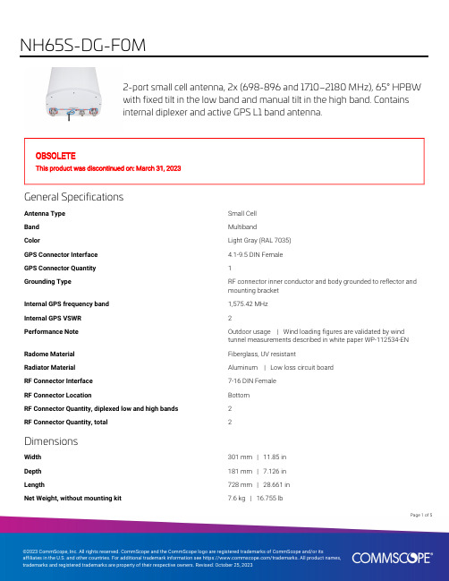
2-port small cell antenna, 2x (698-896 and 1710–2180 MHz), 65° HPBWwith fixed tilt in the low band and manual tilt in the high band. Containsinternal diplexer and active GPS L1 band antenna.OBSOLETEThis product was discontinued on: March 31, 2023General SpecificationsAntenna Type Small CellBand MultibandColor Light Gray (RAL 7035)GPS Connector Interface 4.1-9.5 DIN FemaleGPS Connector Quantity1Grounding Type RF connector inner conductor and body grounded to reflector andmounting bracketInternal GPS frequency band1,575.42 MHzInternal GPS VSWR2Performance Note Outdoor usage | Wind loading figures are validated by windtunnel measurements described in white paper WP-112534-EN Radome Material Fiberglass, UV resistantRadiator Material Aluminum | Low loss circuit boardRF Connector Interface7-16 DIN FemaleRF Connector Location BottomRF Connector Quantity, diplexed low and high bands2RF Connector Quantity, total2DimensionsWidth301 mm | 11.85 inDepth181 mm | 7.126 inLength728 mm | 28.661 inNet Weight, without mounting kit7.6 kg | 16.755 lb15Page ofElectrical SpecificationsImpedance50 ohmOperating Frequency Band1710 – 2180 MHz | 698 – 896 MHzPolarization±45°Electrical SpecificationsFrequency Band, MHz698–806806–8961710–18801850–19901920–2180 Gain, dBi10.110.51414.114 Beamwidth, Horizontal,degrees6965606061Beamwidth, Vertical, degrees39.935.714.113.513.1 Beam Tilt, degrees000–160–160–16 USLS (First Lobe), dB1515121313Front-to-Back Ratio at 180°,dB2432242525Isolation, Cross Polarization,dB2525252525VSWR | Return loss, dB 1.5 | 14.0 1.5 | 14.0 1.5 | 14.0 1.5 | 14.0 1.5 | 14.0 PIM, 3rd Order, 2 x 20 W, dBc-153-153-153-153-153Input Power per Port,maximum, watts125125125125125 Electrical Specifications, BASTAFrequency Band, MHz698–806806–8961710–18801850–19901920–2180 Gain by all Beam Tilts,average, dBi9.510.113.513.813.6Gain by all Beam TiltsTolerance, dB±1.3±0.8±0.7±0.5±0.6Gain by Beam Tilt, average, dBi 0 ° | 14.08 ° | 13.516 ° | 12.90 ° | 14.28 ° | 13.816 ° | 13.30 ° | 14.08 ° | 13.616 ° | 13.3Beamwidth, HorizontalTolerance, degrees±7.5±4.6±5.1±5.4±7.7Beamwidth, VerticalTolerance, degrees±6±3.2±1.1±0.7±0.8USLS, beampeak to 20° abovebeampeak, dB121313Front-to-Back Total Power at180° ± 30°, dB19202120191617181616Page of25CPR at Boresight, dB1617181616 CPR at Sector, dB959910 Mechanical SpecificationsWind Loading @ Velocity, frontal98.0 N @ 150 km/h (22.0 lbf @ 150 km/h)Wind Loading @ Velocity, lateral77.0 N @ 150 km/h (17.3 lbf @ 150 km/h)Wind Loading @ Velocity, maximum188.0 N @ 150 km/h (42.3 lbf @ 150 km/h) Wind Loading @ Velocity, rear99.0 N @ 150 km/h (22.3 lbf @ 150 km/h)Wind Speed, maximum241 km/h (150 mph)Packaging and WeightsWidth, packed409 mm | 16.102 inDepth, packed299 mm | 11.772 inLength, packed976 mm | 38.425 inWeight, gross13.9 kg | 30.644 lbRegulatory Compliance/CertificationsAgency ClassificationISO 9001:2015Designed, manufactured and/or distributed under this quality management systemREACH-SVHCCompliant as per SVHC revision on /ProductComplianceIncluded ProductsBSAMNT-3–Wide Profile Antenna Downtilt Mounting Kit for 2.4 - 4.5 in (60 - 115 mm) OD round members.Kit contains one scissor top bracket set and one bottom bracket set.* FootnotesPerformance Note Severe environmental conditions may degrade optimum performancePage of35Wide Profile Antenna Downtilt Mounting Kit for 2.4 - 4.5 in (60 - 115 mm)OD round members. Kit contains one scissor top bracket set and onebottom bracket set.Product ClassificationProduct Type Downtilt mounting kitGeneral SpecificationsApplication OutdoorColor SilverDimensionsCompatible Diameter, maximum115 mm | 4.528 inCompatible Diameter, minimum60 mm | 2.362 inWeight, net 6.2 kg | 13.669 lbMaterial SpecificationsMaterial Type Galvanized steelPackaging and WeightsIncluded Brackets | HardwarePackaging quantity1Weight, gross 6.4 kg | 14.11 lbRegulatory Compliance/CertificationsAgency ClassificationCE Compliant with the relevant CE product directivesCHINA-ROHS Below maximum concentration valueISO 9001:2015Designed, manufactured and/or distributed under this quality management systemREACH-SVHC Compliant as per SVHC revision on /ProductComplianceROHS CompliantUK-ROHS Compliant45Page ofPage of 55。
MARUWA MWSL1204 GPS L1 活动天线说明书

1.ScopeThis specification applies to the MARUWA MWSL1204 GPS L1 active antenna, which in addition to the basic MWSL1204 form can be supplied in two optional forms: MWSL1204R supplied with a loosely fitting black radome cap/cover for external use and MWSL1204SB supplied with a loosely fitting plastic sleeve for internal use.2.SpecificationsMinimum Typical Maximum UnitPart Number MWSL1204 (MARUWA dwg No: MEFP12040268140101)Type Dielectric-loaded Quadrifilar HelixConnector Type Refer to embedding information / connection diagramsFrequency 1573.421575.421577.42MHzPolarisation Right-hand Circular PolarisedVoltage (+ve to co-ax centre-wire). 1.83 3.6VCurrent 3.1 3.4 3.9mAGain (no ground-plane)+15+16dBic at zenithBeamwidth >115DegreesBandwidth (3dB)15MHzAxial Ratio <2.0at zenithVSWR <2.0:1 2.3:1Impedance 50OhmsNoise Figure 0.80.9dBInput 3rd Order Intercept Point -7dBmOperating Temperature -40+20+85°C Overall Dimensions Refer to mechanical drawings mmWeight (excl radome or sleeve)7.0grams3.DimensionsBasic MWSL1204 form:Rev.Date Description Approved Checked PreparedO.Leisten K.Inagaki F.Frimpong 0103 Feb. 2015Issue of the first edition Product Specification (Preliminary)MARUWA Antenna ProductsDocument №MEPS-12040042150101MWSL1204Notes:1.MARUWA Europe assembly drawingMEFP12040268140101 applies.2. Units in mm.3. For connection layout and pad-size, through-hole and connector details please refer to padlayout and designation definitions.MWSL1204R form with loosely fitting black radome cap.MWSL1204SB form with loosely fitting translucent sleeve.Rev.Date Description Approved Checked PreparedK.Inagaki F.Frimpong O.Leisten 0103 Feb. 2015Issue of the first edition Notes:1.MARUWA Europe assembly drawingMEFP1204R268140101 applies.2. Units in mm.3. Black cap/radome unit: METC120X0158140101shown fitted but actually shipped separately.4. For connection layout and pad-size, through-hole and connector details please refer to padlayout and designation definitions.Notes:1.MARUWA Europe assembly drawingMEFP1204S278140101 applies.2. Units in mm.3. Translucent sleeveunit: METC120X0198140101shown fitted but actually shipped separately.4. For connection layout and pad-size, through-hole and connector details please refer to padlayout and designation definitions.4.Product DescriptionTypical Gain PatternThe MWSL1204 GPS L1 miniature high-gain active dielectric-loaded antenna uses MARUWA’sdistinctive materials technology to provide unrivalled circularly-polarised gain from a uniquely small volume. It enables excellent GPS performance in tightly integrated devices that require good positional accuracy.By combining a high-quality dielectric antenna with a high-performance low-noise amplifier the MWSL1204 active antenna provides an excellent solution wanting an active gain input.The MWSL1204 antenna has a sharp filtering response and is particularly suitable for applications where:*The device is hand-held, body-worn, or otherwise surrounded by materials of high relative dielectric-constant which would de-tune other antennas.* The antenna is installed in close proximity to other antennas sharing the same device housing and ground-plane: for example Bluetooth®, WiFi, LTE,WiMax and other cellular radio antennas.* The antenna must fit into a very small installation volume with close proximity to other components and little or no space available for a ground-plane.* The GPS receiver requires 20dB or more of input pre-amplification.* The device is noisy and requires low-noise front-end amplification to achieve the required GPS sensitivity.* Excellent performance with extremely low power consumption.* The orientation of the device is random.* The antenna must be embedded into the device.The MWSL1204 antenna is balanced, which isolates it from the device ground enabling it to reject common-mode noise present on the device ground-plane. The construction and materials of the antenna constrain its near-field region to occupy a very small volume so that materials near theantenna cause negligible de-tuning effects. Therefore the antenna maintains its pattern and efficiency in the presence of dielectric loading. The MARUWA MWSL1204 dielectric-loaded antenna also has a useful filtering fuction as the antenna strongly attenuates signals from the cellular and ISM frequency bands.-96-90-84-10-5051015200611172328343945515662687379849096101107113118124129135141146152158163169174180186191197203208214219225231236242248253287293298304309315321326332338343349354Azimuth Gain (G φ) for Elevation (θ)Low Noise Amplifier Characteristics.Wide-band Frequency ResponseAntenna Integration Options Pad Number Function 1Ground 2RF Out, DC In 3GroundDimensions mm 0.1A 5.0B 2.1C 5.75D 2.8E 4.0F 6.2G3.3H9.5J3.1K 3.0Pad Layout and Pad DesignationsRev.Date Description Approved Checked PreparedK.Inagaki F.Frimpong O.Leisten 0103 Feb. 2015Issue of the first edition MWSL1204 antennas may be mounted externally (order MWSL1204R version) orembedded within a device (order MWSL1204SB version). The product is designed to tuneto the correct frequency when the sleeve or radome-cap is fitted. In thecase of externalmounting the device housing should be designed to seal around the radome-cap groove inorder to provide mechanical support. When internally mounted the sleeve should befitted and the antenna can be fitted into a corner cut-out in the device PCB. Adjacentmetal ground-surfaces (PCB ground-layers or screening cans) can uplift the radiationefficiency compared with the antenna operating separately in free-space. For optimumperformance the gap between the antenna and the copper edge of the PCB ground-planeshould be greater than 5mm. MARUWA can provide application notes with integrationguidance. Please contact your MARUWA sales representative for this information.123AC C B DE D EF HJ KGOrdering Guide for the MWSL1204 AntennaMaruwa can supply three options. Please order according the the following table:Please note that when MWSL1204R or MWSL1204SB are ordered the radome or sleeve parts shall be deliveredin separate packaging and will not be fitted to the MWSL1204 product. The radome and sleeve parts are designed to fit loosely.5.Notes1. The contents of this document assure the characteristics and quality of the antenna components themselves.2. Please ensure that they work correctly in the installed configuration and method of use of your equipment.。
双微M系列GNSS产品使用说明书
相关信息
您可以通过以下途径找到本说明书: 1、购买双微 M 系列产品后,仪器箱里会配赠一本《双微 M 系列 GNSS 产 品使用说明书》,方便您操作仪器。 2、登陆双微官方网站 ,在【技术支持】→【双微相关下载】 →【说明书】可下载该电子版说明书。
IV
目录
1 产品介绍................................................................................................. 1 1.1 接收机外观..................................................................................1 1.2 工作模式介绍..............................................................................3 1.2.1 RTK 工作模式................................................................... 3 1.2.2 静态工作模式................................................................... 4 1.3 使用与注意事项......................................................................... 5
5 测量....................................................................................................... 28
卫星天线4.5米天线说明书

SCE-450C型4.5米天线安装、使用、维护手册精彩文档西安航天恒星科技股份有限公司手册使用说明 :SCE-450C型天线是实现C波段与Ku波段共用的卫星地球站天线。
使用时,只需根据不同的使用情况换上C波段馈源或Ku波段馈源即可。
《SCE-450C型4.5米天线安装、使用、维护手册》针对C波段与Ku波段的使用,除了馈源安装方式(附图13A为C波段馈源,13B 为Ku波段馈源)和天线电气特性指标不同外,其余内容全部通用。
精彩文档安全方面的注意事项安全声明:以下声明适用于本手册的全过程。
在天线安装前必须仔细阅读本手册,并切实按照规定的步骤及方法进行操作,以保障人身及设备的安全。
1. 必须严格按照要求制作地基,只有在地基达到预定的强度后,方可对天线进行安装。
2. 在吊装过程中,应注意人员及设备的安全;保证设备在吊装中平稳。
3. 在无吊车情况下安装,应特别小心,以确保人身及设备的安全。
4. 在首次运行前,应对所有有润滑要求的部件进行润滑。
其中,减速器用指定的润滑油润滑;方位轴、俯仰轴用稀油注入油杯润滑;丝杠螺母用润滑脂润滑。
5. 在调整限位器工作时,应特别注意不要使丝杠脱出减速器,尤其是俯仰丝杠脱出减速器将造成天线严重损坏。
在方位、俯仰二丝杠的左,右(或上,下)极限位置限位器安装完毕后,首先进行试运行,确保限位器工作无误。
6. 天线具有软件和硬件两重限位保护。
为确保天线使用安全,在转动天线时,应使用ACU,并将软件限位设置在硬件限位之前。
7. 手轮用后应取下,并装上蜗杆轴盖,切勿将手轮套在蜗杆轴上,以免电动时,发生意外事故。
8. 应注意检查波纹喇叭封口材料是否破损或漏水,尤其是在冰雹或大雨之后,若波纹喇叭口漏水,将影响系统正常工作,严重时造成HPA或SSPA损坏。
若封口材料破损,应及时更换。
精彩文档1. 4.5米天线简介SCE-450C型4.5米卫星通信天线是西安航天恒星科技实业(集团)公司研制生产的卫星通信地球站天线。