空气压差传感器安装调试指引
Series MSX Pro Magnesense 差压传感器安装与操作指南说明书

Series MSX Pro Magnesense ® Differential Pressure TransmitterSpecifications - Installation and Operating InstructionsBulletin P-MSXP-AThe Series MSX Pro Magnesense ® Differential Pressure Transmitter is the professional differential pressure transmitter meeting stringent industry standards with innovative global product design. The device has exceptional stability for use in critical building performance applications with the popular versatility of our original Series MS2 Magnesense ® II transmitter. The MSX Pro simplifies the ordering process to deliver the desired configuration, which reduces product setup time. Pressure ranges of Pa, mm w.c., and in w.c. are available per device. All pressure ranges can be configured in unidirectional or bidirectional modes providing a total of 32 ranges. The MSX Pro transmitter can provide a linear pressure output or a linear velocity output with the square root extraction from the transmitter. Additional parameters have been included to expand the square root capability to calculate flow. Dual voltage and milliamp output signals can be used to provide control and equipment output signal verification.INSTALLATION Surface Mounting:Mount the transmitter on a vertical surface. The pressure sensor measurement is unaffected by orientation, but it is recommended the unit be mounted with the connections facing down to prevent moisture from entering either the pressure ports or the electrical cable entry. Attach the mounting flange to a flat surface using #8 x 1/2˝ pan head sheet metal screws. Do not over tighten.Duct Mounting (Universal model required):Mount the transmitter away from fans, corners, heating and cooling coils and other equipment that will affect the measurement of the pressure.1. To mount the transmitter, drill a .562˝ (12.70 mm) diameter hole into the duct. 2. Screw duct probe into back of housing. Insert transmitter probe into the duct.3. Mark location of mounting holes on duct using mounting flange as template. Drill holes.4. Attach mounting flange to duct with #8 x 1/2˝ pan head sheet metal screws. Do not over tighten screws.5. Place the included cap on the exterior positive pressure port.The Universal model can also be used as a standard wall mount transmitter. In this mode, do not use the duct probe and plug the port on the backside of the transmitterwith the included plug.1-29/32[48.43]1-29/32[48.43]ELECTRICALThe MSX Pro transmitter utilizes a 2-wire 4-20 mA Current Output , or a 3-wire 0-5 V / 0-10 V Voltage Output . It is also capable of Simultaneous Current and Voltage Output . The power and signals interconnect via a removable European-style four conductor terminal block, or optionally, via the included tooless terminal block. 2-Wire 4-20 mA Current OutputThe connections to the transmitter are made through terminals VDC and COM on the terminal block as shown in Figure 1. The terminal block is removable and each of the terminals are labeled next to the terminal block on the circuit board. Polarity is indicated by VDC and COM. See Figure 1.The maximum receiver load resistance (RL) for a given power supply voltage (Vps) is defined by the formula: Shielded 2-wire cable is recommended for control loop wiring. Ground the shield at the power supply end only.The receiver may be connected to either the negative or positive side of the loop, whichever is most convenient. Should polarity of the transmitter or receiver be inadvertently reversed, the loop will not function properly but no damage will be done to the transmitter.The maximum length of connecting wire between the transmitter and the receiver is a function of wire size and receiver resistance. That portion of the total current loop resistance represented by the resistance of the connecting wires themselves should not exceed 10% of the receiver resistance. For extremely long runs (over 1,000 feet), it is desirable to select receivers with lower resistances in order to keep the size and cost of the connecting leads as low as possible. In installations where the connecting run is no more than 100 feet, you can use a connecting lead wire as small as No. 22 ga.Selection of using a DC or AC power supply is made via the terminal block. See Figure 2 for DC Wiring. See Figure 3 for AC Wiring.The terminal block is removable and each of the terminals are labeled next to the terminal block on the circuit board. Positive polarity is indicatedby VOUT. AC/DC selection is made via the terminal block. If the polarity of the transmitter is inadvertently reversed, the unit will not function properly, but no damage will be done to the transmitter.The minimum receiver load is 1 kΩ. The resistance due to the wire should be low compared to the receiver load resistance. While the voltage at the terminal block remains unchanged with a 10 mA current flow, resistive losses in the wiring do cause errors in the voltage delivered to the receiver. For a 1% accurate gage, the resistance of the wires should be less than 0.1% of the value of the receiver load resistance. This will keep the error caused by the current flow below 0.1%.The output across VOUT and COM will be either 0-5 V, 0-10 V depending on the DIP switch setting. See DIP Switch Settings Section for more information.DC POWER SUPPLY 10-36 VDCV A CV D CC O MV O U TCURRENT RECEIVER+--+DC POWER SUPPLY 17-36 VDCVOLTAGE RECEIVER-++-V A CV D CC O MV O U T AC POWER SUPPLY 21.6-33 VACVOLTAGE RECEIVERV A CV D CC O MV O U T -+DO NOT EXCEED SPECIFIED SUPPLY VOLTAGE RATINGS. PERMANENT DAMAGE NOT COVERED BY WARRANTY WILLRESULT. SIMULTANEOUS OUTPUTS ARE NOT DESIGNED FOR AC VOLTAGE OPERATION.DO NOT EXCEED SPECIFIED SUPPLY VOLTAGE RATINGS. PERMANENT DAMAGE NOT COVERED BY WARRANTY WILLRESULT.Figure 1Figure 2: DC wiringFigure 3: AC wiringR L =V ps - 10.020 mA DC If equipped, the LCD must be removed before wiring. Pull the LCD directly away from the product to remove. Reinstall the LCD afterwiring is completed.Simultaneous Current and Voltage OutputThe terminal block is removable and each of the terminals is labeled underneath the terminal block on the circuit board. Positive polarity is indicated by VOUT. The VDC terminal and a DC power supply must be used for Simultaneous Current and Voltage Output. The voltage output and the power supply must have separate wire leads that are only joined at terminal 2 of the transmitter. Additional error may occur for the voltage output if a single wire is used or if the wires are joined at the power supply or receiver.For the current output, the maximum allowable loop resistance (wiring + receiver resistance) is dependent on the power supply. The maximum loop voltage drop must not reduce the transmitter voltage below 17 V. The maximum loop resistance (R MAX ) for a given power supply voltage (V PS ) can be calculated using the following equation:The equation uses 17.0 instead of 10.0 as seen in the equation earlier with Figure 1. This represents the minimum voltage supply which is higher on the simultaneous output configuration due to the requirements of the voltage outputs.Shielded 4-wire cable is recommended for control loop wiring. Ground the shield at the power supply end only. Should the polarity of the transmitter or receiver be inadvertently reversed, the unit will not function properly, but no damage will be done to the transmitter.For voltage outputs, the minimum receiver load is 1 kΩ. The resistance due to the wire should be low compared to the receiver load resistance. While the voltage at the terminal block remains unchanged with a 10 mA current flow, resistive losses in the wiring do cause errors in the voltage delivered to the receiver. For a 1% accurate gage, the resistance of the wires should be less than 0.1% of the value of the receiver load resistance. This will keep the error caused by the current flow below 0.1%.The output across VOUT and COM will be either 0-5 V or 0-10 V depending on the DIP switch setting. See DIP Switch Settings Section for more information.Power SupplyRefer to the following tables for the required supply rating.DIP SWITCH SETTINGSDIP switch settings are marked directly on the PCBA as shown in Figure 5. Switches are factory-set, based on the order configuration. You can also use a small screwdriver or pen to change the position of the switches.Key To DIP Switch SettingsSwitches are numbered 1 to 8 beginning on the left.DIP Switches 1 and 2 - Unit of Measure SelectionDIP Switches 1 and 2 work as a pair to select the unit of measure. V A CV D C C O M V O U T DC POWERSUPPLY 10-36 VDCVOLTAGE RECEIVERCURRENT RECEIVER+-+--+Figure 4: Simultaneous current and voltage output wiringDO NOT EXCEED SPECIFIED SUPPLY VOLTAGE RATINGS. PERMANENT DAMAGE NOT COVERED BY WARRANTY WILLRESULT. SIMULTANEOUSOUTPUTS ARE NOT DESIGNED FOR AC VOLTAGE OPERATION.Figure 5 is a depiction of a 5 in w.c. pressure board. Other pressure boards, while similar, will vary from the below.There are no hazardous voltages if supplied power is within thespecified range. However, it is a good idea to shut control systemsdown while changing DIP switches to prevent erratic control system behavior.Figure 5: 5 in w.c. pressure boardR MAX =(V PS – 17.0) 20 mA DCDIP Switch 3 - Pressure vs Velocity/Flow Mode of OperationDIP Switch 3 toggles between pressure output vs velocity or flow output.• When the switch is in the OFF or down position, the device is in Pressure Mode.• When the switch is in the ON or up position, the device is in Velocity/Flow Mode. DIP Switch 4 - Voltage Output RangeVoltage output range can be either 0-10 V or 0-5 V depending on the position of DIP Switch 4.• When the switch is in the OFF or down position, the output will be 0-10 V• When the switch is in the ON or up position, the output will be 0-5 V.DIP Switch 5 - Unidirectional vs Bidirectional OutputDIP Switch 5 can be set to measure pressure in one direction (unidirectional) or in both directions (bidirectional).• When the switch is in the OFF or down direction, the transmitter will be set for uni-directional and will be 0 based (i.e. 0 to 5 in w.c.).• When the switch is in the ON or up position, the transmitter will be set forbidirectional and will be ± the maximum of the selected range (i.e. ±5 in w.c.). DIP Switch 6 - Response Time SelectionDIP Switch 6 toggles to select the desired response time.• When the switch is in the OFF or down direction, the transmitter response time will be instantaneous.• When the switch is in the ON or up direction, the response time will be 3 seconds. DIP Switches 7 and 8 - Maximum Range Selection (Pressure)DIP switches 7 and 8 work as a pair to select the maximum range output of the transmitter. Use the tables below to navigate pressure range selection. Alternatively, if using the device for velocity and flow, proceed to the next section.DIP Switches 7 and 8 - Maximum Range Selection (Velocity/Flow)DIP switches 7 and 8 work as a pair to select the maximum range output of the transmitter. Use the tables below to navigate velocity and flow range selection. CALIBRATIONThe transmitter security feature must be unlocked before calibration is accessible. See Section Program Menu-Menu Access Security. There is a 3 second delay from the time the zero or span calibration buttons are released until the time that the change in calibration takes place. This delay is used to prevent stress related offsets on the lower ranges.Zero CalibrationThe zero calibration can be set by applying zero pressure to both of the pressure ports and pressing the zero button for 3 seconds. If the LCD display is present, the display will read ZERO and then sequence back to the home display.The span calibration function allows the pressure value to be adjusted so that the currently applied pressure is the maximum configured pressure. This will in turn set the maximum analog output at the set pressure. It is recommended that the ZERO function be applied before performing a span. Apply the maximum desired pressure to the device, press and hold span for 3 seconds. If the LCD display is present, SPAN is displayed. The span function will be processed 3 seconds after the span button is released.For a positive span, apply pressure to the positive “+” port.LCD DISPLAYThe LCD comes with a housing cover, which contains a window. The display plugs into the pins on top of the circuit board. The LCD is 180° rotatable so that it will read properly if the device must be mounted with the connections facing up.The following error messages will appear if an LCD is present and the device is an error state.PROGRAM MENUHome MenuDuring normal operation, the display will be in the Home Menu and will display the current measured pressure and the engineering units.Menu Access SecurityBy default, a PIN code is not required to enter the configuration menus. However, if access to the menus needs to be restricted, follow the steps below.1. While in the Home Menu, press and hold the Zero and Span buttons until “PIN” is displayed.2. Press and hold the Zero and Span buttons until the current PIN setting isdisplayed (default is 0000).3. Use the Zero button to increment the selected digit (denoted by the caron ) orpress the Span button to select the next digit to the right.4. Any value between 0001 and 9999 will result in the requirement to enter the PINeach time the menu is entered. The value 0000 will disable the PIN entryrequirement.5. Press and hold the Span button until the next menu is displayed. PIN security setup is now complete.MAINTENANCE/REPAIRUpon final installation of the Series MSX Pro, no routine maintenance is required. The Series MSX Pro is not field serviceable and should be returned if repair is needed. Field repair should not be attempted and may void warranty.WARRANTY/RETURNRefer to “Terms and Conditions of Sale” in our catalog and on our website. Contact customer service to receive a Return Materials Authorization (RMA) number before shipping the product back for repair. Be sure to include a brief description of theproblem plus any additional application notes.This symbol indicates waste electrical products should not be disposedof with household waste. Please recycle where facilities exist. Check withyour Local Authority or retailer for recycling advice.DISPLAY ALL SEGMENTSHOME SCREEN (MODE = PRESSURE)FIRMWARE VERSION(MAY VARY)PIN MENUK-FACTOR MENUPRESSURE MENU (OUTPUT LOW MENU)PRESSURE MENU (OUTPUT HIGH MENU)PRESSURE MENU (ALARM LOW)PRESSURE MENU (ALARM HIGH)RESET MENUVELOCITY MENU(OUTPUT LOW MENU)VELOCITY MENU(OUTPUT HIGH MENU)RESET MENUMSX PRO FLOW SETTINGS FLOWCHARTFLOW MENU(AREA)FLOW MENU(OUTPUT LOW MENU)FLOW MENU(OUTPUT HIGH MENU)RESET MENUPrinted in U.S.A. 8/20FR# 444576-10©Copyright 2020 Dwyer Instruments, Inc.NOTES__________________________________________________________________________________________________________________________________________________________________________________________________________________________________________________________________________________________________________________________________________________________________________________________________________________________________________________________________________________________________________________________________________________________________________________________________________________________________________________________________________________________________________________________________________________________________________________________________________________________________________________________________________________________________________________________________________________________________________________________________________________________________________________________________________________________________________________________________________________________________________________________________________________________________________________________________________________________________________________________________________________________________________________________________________________________________________________________________________________________________________________________________________________________________________________________________________________________________________________________________________________________________________________________________________________________________________________________________________________________________________________________________________________________________________________________________________________________________________________________________________________________________________________________________________________________________________________________________________________________________________________________________________________________________________________________________________________________________________________________________________________________________________________________________________________________________________________________________________________________________________________________________________________________________________________________________________________________________________________________________________________________________________________________________________________________________________________________________________________________________________________________________________________________________________________________________________________________________________________________________________________________________________________________________________________________________________________________________________________________________________________________________________________________________________________________________________________________________________________________________________________________________________________________________________________________________________________________________________________________________________________________________________________________________________________________。
压力传感器安装调试说明书

压力传感器安装调试说明书一、前言为了确保压力传感器的安装信号稳定,准确监测压力状态并进行数据采集与处理,特编写此安装调试说明书。
本说明书旨在提供正确的操作步骤,以保证压力传感器系统的正常运行和有效性。
二、安装前准备1. 确认压力传感器型号和规格,验证其与所需安装应用的匹配程度。
2. 检查压力传感器的外观,确保无明显损坏和质量问题。
3. 根据安装环境和指示要求,选择适当的安装位置。
确保其与被测压力贴合并紧密连接。
4. 確保安裝位置周围区域整潔無障礙,便于施工人员進行操作。
三、安装步骤1. 按照被测压力管道的特性和要求,选择合适的接头和密封材料。
2. 清洁安装位置,确保无异物和杂质。
如需要,可使用酒精或清洁剂,但请注意不要使用腐蚀性物质。
3. 将压力传感器与被测压力管道连接。
在连接前,确保接头、密封件和传感器本体的清洁度。
4. 完成连接后,用扳手适当拧紧接头,确保密封性能。
四、传感器校验1. 安装完成后,先检查压力传感器与被测压力管道的连接是否牢固。
2. 通过液压或气压系统,逐步增加压力,观察传感器的响应情况。
确保传感器能准确读取压力变化并输出正确的信号。
3. 监测传感器与数据采集系统的连接是否正常。
可通过检验仪器或相应软件进行测试。
五、注意事项1. 安装过程中应确保施工人员操作安全,防止发生人员伤害和设备损坏。
2. 请避免过度拧紧接头,以免损坏传感器或被测压力管道。
3. 定期检查压力传感器,确保其连接可靠,并补充适量的润滑剂以保持正常工作。
4. 避免传感器长时间暴露于易燃、腐蚀性气体或液体环境中,以免影响传感器的性能和寿命。
5. 在使用过程中,如发现任何异常情况或故障,请立即停止使用,并联系售后服务部门进行维修或更换。
六、总结本安装调试说明书详细介绍了压力传感器的安装步骤和注意事项。
在安装过程中,请严格按照本说明书的要求进行操作,以确保安全和可靠性。
如有任何疑问或问题,请联系我们的技术支持部门。
我们将全力为您解决问题,保证压力传感器系统的正常运行。
压差传感器安装方法

压差传感器安装方法
压差传感器的安装方法可以根据具体的应用场景和设备来确定,下面是一般的安装步骤:
1.选择安装位置:根据需要测量的压差范围和实际应用场景,选择一个合适的安装位置。
通常,应选择在管道或容器的侧壁上,以确保正常的流体流动,并避免阻塞或漏损问题。
2.设备准备:按照压差传感器的规格和要求进行设备准备工作。
包括清洁传感器和连接部件,确保其无灰尘、油污或其他杂质。
3.连接传感器:使用适当的连接件将压差传感器安装在所选择的位置上。
根据传感器的设计,可以选择螺纹连接、法兰连接或其他合适的安装方式。
确保连接紧固,以防止泄漏。
4.调整传感器位置:根据需要调整传感器的安装位置,确保其与流体的流动方向垂直,并保持合适的距离。
避免传感器受到外部冲击或振动,以免影响测量结果。
5.连接电源和信号线:根据传感器的电路设计和接线要求,连接电源和信号线。
确保电源稳定和信号线的正确接地,以获得准确的测量结果。
6.测试和校准:在安装完成后,进行测试和校准工作。
使用适当的校准设备和程
序,确保传感器的测量结果与实际压差值相符合。
7.固定传感器:最后,使用适当的固定装置将传感器牢固地固定在安装位置上,防止其松动或移位,以确保长期稳定和可靠的使用。
请注意,在任何安装过程中,都要遵循安全操作规程,并由合格的技术人员进行安装和调试工作。
气压传感器及调压阀的安装(相对位置示意)

调压阀及气压传感器安装说明
一型号及参数
为了测量制动管路气压的动态变化,需要安装气压传感器,采用欧锐特科技生产的ORT-12型气体压力传感器,外形如图1所示,传感器的相关参数如表1所示。
气压传感器的位置在回馈制动调压阀之后,ABS调压阀之前,前后制动管路各有一个,在完成制动系统参数匹配与标定之后,气压传感器可以方便的拆卸,采用相应螺纹的螺栓将气压传感器的安装孔堵住,保证不漏气。
传感器电源及信号接口采用插拔式接头,在控制器附近及传感器附近各有一个接口。
图1
表1 ORT-12型气体压力传感器主要参数
参数名称参数值
量程0~1MPa
输出1~5V
响应时间1ms
工作温度-25℃~70℃
灵敏度温度系数0.01
二安装说明
如下图所示,回收制动的部件的安装位置。
图回收制动的部件在制动气路中的相对安装位置简图
从图中可见,气压传感器需要使用一个三通才能测量气路中的气压。
回馈制动调压阀需要串联在快放阀及继动阀的后面。
快放阀及继动阀原来的两个出口只使用一个,另一个堵住或接刹车灯/倒车灯传感器。
三通已经提供,需要工厂提供垫片,尺寸如附图。
压力传感器的正确连接与校准方法
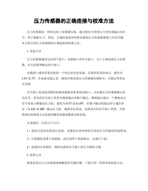
压力传感器的正确连接与校准方法压力传感器是一种常见的工业测量仪器,通过量化介质的压力变化来输出电信号,用于测量压力。
然而,正确的连接和校准是确保压力传感器准确工作的关键。
本文将介绍压力传感器的正确连接和校准方法。
1. 连接方法压力传感器通常包含两个接口:电源接口和信号接口。
为了正确连接压力传感器,首先需要理解这两个接口。
电源接口通常需要连接到一个恒定的直流电源,以提供所需的电压,通常为3.3V或5V。
在连接电源之前,确保仔细查看压力传感器的规格书,以确定所需电压范围。
信号接口是连接到微控制器或数据采集系统的接口,以传输压力传感器输出的电信号。
常见的信号接口类型有模拟输出和数字输出。
模拟输出通过一个模拟电压信号来表示测量的压力值,通常为0-5V或0-10V。
而数字输出则通过串行通信协议(如I2C或SPI)输出压力值。
根据实际需求,选择适合的信号接口类型,并按照相应的接线方式连接到微控制器或数据采集系统。
在连接时,注意以下几点:1)使用合适的电缆进行连接,电缆的长度和材质应考虑信号传输的性能要求;2)尽量避免电缆与电源线、高压线等干扰源靠近,以减少干扰;3)连接时注意极性,确保电源和信号接口的正负极性正确。
2. 校准方法校准是保证压力传感器准确测量的关键步骤,下面介绍一种简单的校准方法。
首先,需要一台已知精确值的压力测量仪器(如校准泵),以提供参考压力值。
将该仪器连接到压力传感器的测量介质端口上。
接下来,按照以下步骤进行校准:1)将校准泵压力设置为已知值,记录校准泵的读数和压力传感器的输出电信号;2)持续改变校准泵的压力,记录对应的读数和电信号,确保覆盖整个测量范围;3)绘制读数和电信号之间的关系曲线;4)根据曲线拟合出校准方程,将传感器输出的电信号转换为对应的压力值。
校准完成后,可以使用该校准方程来进行实际压力测量。
需注意的是,校准应在实际应用前定期进行,以确保测量准确性。
此外,应根据实际情况选择合适的校准时间间隔,以平衡校准成本和准确性要求。
差压传感器的安装方法

差压传感器的安装方法引言差压传感器是一种广泛应用于工业控制和仪表领域的传感器,可用于测量流体中的压力差。
它具有灵敏度高、响应速度快、稳定性好等特点,在工程应用中得到了广泛的应用。
本文将介绍差压传感器的安装方法。
准备工作在安装差压传感器之前,我们需要准备一些必要的工具和材料:- 差压传感器- 密封垫片或硅脂- 电缆及接头- 合适的螺栓和垫片- 扳手和螺丝刀- 灯具或手电筒(用于光源)安装步骤以下是差压传感器的安装步骤:1. 确定安装位置:首先确定差压传感器的安装位置。
传感器应安装在能够准确反映流体压力的位置,避免安装在有振动、冲击或高温的地方。
2. 清洁安装位置:在安装之前,需将安装位置彻底清洁,确保表面没有灰尘、油污和其他杂物。
可以使用酒精或清洁剂擦拭表面。
3. 安装密封垫片:在传感器表面涂抹密封垫片或硅脂。
这有助于保护传感器,并确保传感器与安装位置之间的密封性。
注意,不要过度涂抹,以免影响传感器的测量精度。
4. 固定传感器:将差压传感器放置在安装位置上,并使用螺栓和垫片固定传感器。
根据情况使用扳手或螺丝刀适当地拧紧螺栓。
5. 连接电缆:将传感器的电缆与现场控制系统或仪表连接。
确保电缆连接可靠,避免松动或断开。
6. 安装附件:根据需要,可以安装附件,如温度补偿装置、防护罩等。
7. 检查安装质量:安装完成后,检查传感器的安装质量,确保传感器牢固可靠,并且与流体接点稳定。
8. 测试和校验:在使用差压传感器前,需要进行测试和校验。
使用专用设备或测试仪器对传感器进行校验,并根据校验结果调整传感器的零点和灵敏度。
注意事项在安装差压传感器时,需要注意以下事项:- 避免安装在高温或有振动的环境中,以免影响传感器的测量精度。
- 注意保护传感器表面,避免刮伤或损坏。
- 选择合适的螺栓和垫片,确保传感器的固定可靠。
不要过度拧紧螺栓,以免破坏传感器。
- 在连接电缆时,确保电缆连接牢固可靠,避免因松动而影响传感器的工作。
楼控传感器、阀门、DDC安装与调试

1.1.1调试和安装图纸(一)、传感器安装图纸以下是建筑设备监控系统中的典型传感器的安装图纸:1、室外温度传感器安装图纸:2、房间压差传感器安装图纸3、防冻开关安装图纸4、压差开关安装图纸5、空气压力传感器安装图纸6、水流开关安装图纸7、水压差传感器安装图纸8、水压力传感器安装图纸9、液位开关安装图纸(二)、典型阀门安装图纸(三)、控制器安装图纸1、PXC控制器安装图纸2、PXC modular &TX-I/O1.1.2调试指南(一)、调试应具备的条件(1)、受BAS监控的设备必须先手动调试通过;(2)、各设备机房必须有良好的照明和正确的电源;(3)、当涉及与其他有关厂家机电设备接口时,厂家必须有人配合;(4)、BA监控中心必须装修完整,清扫干净,并且有充足的照明和电源;(5)、系统调试的环境要求:温度0-49℃,相对湿度≤93%;(二)、调试工具(1)、手提电脑三台;(2)、对讲机若干;(3)、万用表若干;(4)、常用电工工具若干;(5)、标准温湿度计2台;(6)、标准压差计2台(7)、信号发生器2台;(三)、调试指南由于建筑设备监控系统结构特殊、设备分散,线路较长等原因,整个建筑设备监控系统按照以下指南来完成调试:建筑设备监控系统将按照如下的流程进行调试:(1)、BAS设备与受控设备的单体调试○1、传感器调试由于传感器的精度是工厂在生产时,由其材料、原理、制作工艺以及校正设备的精度而定,因此,如无专业设备及专门机构一般不对传感器的精度作现场校正,如有特殊要求的客户,则在订购设备时尽量选择带出厂校验报告的型号或厂家。
如客户对传感器的精度有疑问则可用分开测试DDC及传感器的方法来确认设备的好坏或精度,对DDC检测时,可用标准电阻箱或信号发生器等设备,来模拟传感器的信号,观察DDC中的响应是否正确,然后再用万用表来检测传感器的输出,与标准值比较,观察结果是否在允许范围内。
在BA系统中常用的传感器由以下几种,现分别介绍这几种传感器的调试方法:第一类:1000欧姆RTD型温度传感器:此种传感器如544-339,常用于新风温度、送风温度及回风温度等,水管型的有544-577,常用于冷冻冷却水系统及热交换系统,在调试前可先用万表测量其电阻值,与标准的电阻温度对照表比较,读出此传感器的温度值与标准温度计测得的值比较,判断是否在精度范围内,以决定是否更换此传感器。
压差传感器安装方法
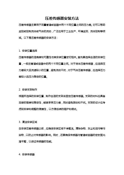
压差传感器安装方法压差传感器主要用于测量管道或容器中两个不同位置之间的压力差。
它可以帮助监控或控制流体或气体的流动,广泛应用于工业生产、环境监测、流体控制等领域。
以下是压差传感器的安装方法:1. 安装位置选择压差传感器的准确度和可靠性与其安装位置密切相关。
首先要选择合适的安装位置,一般在管道或容器中的两个不同位置之间。
对于液体压差传感器,应选择压力差较大且流速较小的位置,避免流动干扰;对于气体压差传感器,应选择压力差较小且压力稳定的位置。
2. 安装支架制作根据所选择的安装位置,制作合适的支架来固定压差传感器。
支架的材料应具备足够的强度和稳定性,能够承受压力差,同时避免振动和干扰。
支架的设计应考虑到安装和调整的便捷性,以方便后续的维护和调试。
3. 清洁安装区域在安装压差传感器之前,应确保安装区域干净整洁。
清除杂物、灰尘和油污等污染物,以防止对传感器的影响。
同时,还要确保传感器与管道或容器的密封面光滑平整,以保证传感器的性能。
4. 安装传感器将压差传感器固定在支架上,并采取适当的固定方法。
通常使用螺栓、法兰等方式进行固定,确保传感器的牢固稳定。
在安装过程中,要注意不要过度拧紧螺栓,否则可能导致传感器损坏。
5. 连接管路根据实际情况选择合适的管路连接方式,将管道或容器与压差传感器连接起来。
连接过程中要遵循正确的操作方法,确保连接紧密,防止泄漏和松动。
同时,还要注意管路的布置,避免弯曲、拉伸和挤压等对传感器的影响。
6. 封装保护为了保护压差传感器免受外部环境的影响,可以将传感器进行封装保护。
常见的封装形式有防护壳、密封胶等,可根据具体情况选择合适的封装方式。
封装后,还应进行防水、防尘和防腐处理,以延长传感器的使用寿命。
7. 调试和测试安装完成后,需进行相应的调试和测试,以确保压差传感器的准确度和灵敏度。
可以通过外部设备接口或控制器进行校准和调整,确保传感器的测量精度符合要求。
同时,还要进行压力泄漏和连接可靠性测试,以确保系统的安全性和稳定性。
- 1、下载文档前请自行甄别文档内容的完整性,平台不提供额外的编辑、内容补充、找答案等附加服务。
- 2、"仅部分预览"的文档,不可在线预览部分如存在完整性等问题,可反馈申请退款(可完整预览的文档不适用该条件!)。
- 3、如文档侵犯您的权益,请联系客服反馈,我们会尽快为您处理(人工客服工作时间:9:00-18:30)。
ASD1600 CWU
ASD1600 CWU
高架地板 接正压
H
接正压
0.5H 0.8X
X
压差传感器压力检测软管的安装
空调机组安装于机房内单侧
不能将空气压力探测点放置在有出风口的 地板下方附近。 此检测点必须安 装在没有空气流 动的房间内
接负压
压差传感器安装于室内或地板下方 1、压差传感器的连接线必须使 用0.75mm2三芯屏蔽线并穿电 线管 2、软管内径Ø = 5.5 mm 3、 软管必须安装在镀锌钢管或 塑料电线管内,以防软管被硬 物扎破或有折弯而影响空气压 力的检测 4、检测点必须垂直于空气的流 向以便能够检测到空气静压 EAIO板
不能将空气压力探测点放置在有出风口的 地板下方附近。 此检测点必须安 装在没有空气流 动的房间内
接负压
压差传感器安装于室内或地板下方 EAIO板 1、压差传感器的连接线必须使 用0.75mm2三芯屏蔽线并穿电 线管 2、软管内径Ø = 5.5 mm 3、 软管必须安装在镀锌钢管或 塑料电线管内,以防软管被硬 物扎破或有折弯而影响空气压 力的检测 4、检测点必须垂直于空气的流 向以便能够检测到空气静压 EAIO板
空气压差传感器 安装指引
Page 1
压差传感器参数
配件编号:M26174 型号:984M523304
984M 5 2 3 类型 IP 保护等级 可配置压力范围 压力单位 压差传感器 IP 54 带电线接口M16x1.5 0 ... 100 Pa (1.0 mbar) 0 ... 250 Pa (2.5 mbar) Pascal
Page 5
压差传感器接线
4 3 2
SA GOห้องสมุดไป่ตู้Y
Switching output, npn Ground GND Output signal 0 … 10 V / 4 ... 20 mA
1
G
Supply voltage 24 VAC/ VDC
Page 6
压差传感器压力检测软管的安装
空调机组安装于机房内两侧 接负压
此检测点必须安 装在没有空气流 动的房间内
接负压
压差传感器安装于室内或地板下方 EAIO板
EAIO板
ASD1600 CWU
ASD1600 CWU
高架地板 接正压
H
接正压
0.5H 0.8X
X
压差传感器压力检测软管的安装
空调机组安装于独立空调机房内单侧
不能将空气压力探测点放置在有出风口的 地板下方附近。
压差传感器安装于 室内或地板下方 EAIO板
ASD1600 CWU
H
高架地板 接正压 X 0.5H 0.65X
压差传感器与EAIO板的接线
压差传感器连接至EAIO板的接线端子 连接线为0.75mm2三芯屏蔽线并穿电线管
压差传感器接线端子 1: Input(24VAC/DC) 2: Output 3: Ground(G0) 连接线的屏蔽线 电控箱内接线端子 电控箱内接线端子排X2的A1 EAIO板的X1引脚的第2个:AIN6 EAIO板的X1引脚的第3个:GND 电控箱内接线端子排X0
此检测点必须安 装在没有空气流 动的房间内
接负压
1、压差传感器的连接线必须 使用0.75mm2三芯屏蔽线并穿 电线管 2、软管内径Ø = 5.5 mm 3、 软管必须安装在镀锌钢管 或塑料电线管内,以防软管被 硬物扎破或有折弯而影响空气 压力的检测 4、检测点必须垂直于空气的流 向以便能够检测到空气静压
3
0 4
信号输出和电源
显示屏 接线方式
4 ... 20 mA or 0 ... 10 V, 3线 24 Vac/Vdc, 带开关
无显示屏 通过螺纹接线排接线
Page 2
压差传感器尺寸
Page 3
压差传感器安装
软管内径Ø = 5.5 mm 软管要求:25 kPa [250 mbar] P1 = 正压 P2 = 负压 P1 + P2 = 压差
ASD1600 CWU
H
高架地板 接正压 X 0.5H 0.65X
压差传感器压力检测软管的安装
空调机组安装于独立空调机房内两侧
不能将空气压力探测点放置在有出风口的 地板下方附近。
接负压
1、压差传感器的连接线 必须使用0.75mm2三芯 屏蔽线并穿电线管 2、软管内径Ø = 5.5 mm 3、 软管必须安装在镀 锌钢管或塑料电线管内 ,以防软管被硬物扎破 或有折弯而影响空气压 力的检测 4、检测点必须垂直于空 气的流向以便能够检测 到空气静压
Page 4
压差传感器参数设定
闭合 默认跳线 压力范围 反应速度 不使用 输出信号 备用 跳线 M=模式 S=设定 指示灯 0…10 V 4…20 mA 低 0 ... 100 Pa 慢 1s 高 0 ... 250 Pa 快 100ms 断开
Offset Calibration偏移误差校正 This function can be used to correct the zero-point deviation (offset) of the output signal in depressurized state (example: to 0 V/4mA at zero Pa). Disconnect the unit from the pressure by opening both hose nozzles or removing the hoses. Then press the "M" button for 5 s. Setting of Switching Output This function is used to set the switching output to "switched through" for a pressure you have defined. Apply the pressure or pressure differential at which the switching output is to be connected. Then press the "S" button for 5 s until the LED flashes quickly (= value is saved). The LED lights up as soon as the defined pressure is reached or exceeded.