空调箱手册(Word版)
空调安装及操作手册说明书

Press and select the trial operation (COOL or HEAT).Press to turn on the system.Press both of and at the same time.Press , select “ ”,and press for confirmation.• Trial operation will stop automatically after about 30 minutes.To stop the operation, press .• Some of the functions cannot be used in the trial operation mode.• The air conditioner draws a small amount of power in its standby mode. If the system is not to be used for some time after installation, shut off the circuit breaker to eliminate unnecessary power consumption.• If the circuit breaker trips to shut off the power to the air conditioner, the system will restore the original operation mode when the circuit breaker is opened again..(ﺔﺌﻓﺪﺘﻟﺍ ﻭﺃ ﺪﻳﺮﺒﺘﻟﺍ) ﻲﺒﻳﺮﺠﺘﻟﺍ ﻞﻴﻐﺸﺘﻟﺍ ﺭﺎﻴﺘﺧﺎﺑ ﻢﻗﻭ ﻂﻐﺿﺍ.ﻡﺎﻈﻨﻟﺍ ﻞﻴﻐﺸﺘﻟ ﻂﻐﺿﺍ.ﺖﻗﻮﻟﺍ ﺲﻔﻧ ﻲﻓ ﻭ ﻦﻣ ﻼﻛ ﻂﻐﺿﺍﺭﺎﻴﺘﺧﺎﺑ ﻢﻗﻭ ﻂﻐﺿﺍﻴﺋﺎﻘﻠﺗ ﻲﺒﻳﺮﺠﺘﻟﺍ ﻞﻴﻐﺸﺘﻟﺍ ﻒﻗﻮﺘﻴﺳ. ﻂﻐﺿﺍ ،ﻞﻴﻐﺸﺘﻟﺍ ﻑﺎﻘﻳﻹ.ﻲﺒﻳﺮﺠﺘﻟﺍ ﻞﻴﻐﺸﺘﻟﺍ ﻊﺿﻭ ﻲﻓ ﻒﺋﺎﻇﻮﻟﺍ ﺾﻌﺑ ﻝﺎﻤﻌﺘﺳﺍ ﺭﺬﻌﺘﻳﻴﺌﺿ ﺍﺭﺍﺪﻘﻣ ﺎ.ﻱﺭﻭﺮﻀﻟﺍ ﺮﻴﻏ ﺭﺎﻴﺘﻟﺍ ﻙﻼﻬﺘﺳﺍ ﻦﻣ ﺪﺤﻠﻟ ﺔﻴﺋﺎﺑﺮﻬﻜﻟﺍ ﺓﺮﺋﺍﺪﻟﺍ ﻊﻃﺎﻗ ﻑﺎﻘﻳﺈﺑ ﻢﻗPress and select the trial operation (COOL or HEAT).Press to turn on the system.Press both of and at the same time.Press , select “ ”,and press for confirmation.• Trial operation will stop automatically after about 30 minutes.To stop the operation, press .• Some of the functions cannot be used in the trial operation mode.• The air conditioner draws a small amount of power in its standby mode. If the system is not to be used for some time after installation, shut off the circuit breaker to eliminate unnecessary power consumption.• If the circuit breaker trips to shut off the power to the air conditioner, the system will restore the original operation mode when the circuit breaker is opened again..(ﺔﺌﻓﺪﺘﻟﺍ ﻭﺃ ﺪﻳﺮﺒﺘﻟﺍ) ﻲﺒﻳﺮﺠﺘﻟﺍ ﻞﻴﻐﺸﺘﻟﺍ ﺭﺎﻴﺘﺧﺎﺑ ﻢﻗﻭ ﻂﻐﺿﺍ.ﻡﺎﻈﻨﻟﺍ ﻞﻴﻐﺸﺘﻟ ﻂﻐﺿﺍ.ﺖﻗﻮﻟﺍ ﺲﻔﻧ ﻲﻓ ﻭ ﻦﻣ ﻼﻛ ﻂﻐﺿﺍﺭﺎﻴﺘﺧﺎﺑ ﻢﻗﻭ ﻂﻐﺿﺍﻴﺋﺎﻘﻠﺗ ﻲﺒﻳﺮﺠﺘﻟﺍ ﻞﻴﻐﺸﺘﻟﺍ ﻒﻗﻮﺘﻴﺳ. ﻂﻐﺿﺍ ،ﻞﻴﻐﺸﺘﻟﺍ ﻑﺎﻘﻳﻹ.ﻲﺒﻳﺮﺠﺘﻟﺍ ﻞﻴﻐﺸﺘﻟﺍ ﻊﺿﻭ ﻲﻓ ﻒﺋﺎﻇﻮﻟﺍ ﺾﻌﺑ ﻝﺎﻤﻌﺘﺳﺍ ﺭﺬﻌﺘﻳﻴﺌﺿ ﺍﺭﺍﺪﻘﻣ ﺎ.ﻱﺭﻭﺮﻀﻟﺍ ﺮﻴﻏ ﺭﺎﻴﺘﻟﺍ ﻙﻼﻬﺘﺳﺍ ﻦﻣ ﺪﺤﻠﻟ ﺔﻴﺋﺎﺑﺮﻬﻜﻟﺍ ﺓﺮﺋﺍﺪﻟﺍ ﻊﻃﺎﻗ ﻑﺎﻘﻳﺈﺑ ﻢﻗCAUTIONWhen pressing the switch, do not touch the terminal block. It has a high voltage, and touching it could cause electric shock.Press both of and at the same time. 4) Press , select “ ”, and press Forced cooling operation will stop automatically after about 30 minutes. anof an.ﺔﻴﺋﺎﺑﺮﻬﻛ ﺔﻣﺪﺻ ﺙﻭﺪﺣ ﻲﻓ ﺐﺒﺴﺘﻳ ﺪﻗ ﻪﺴﳌﻭ ،ﺔﻴﻟﺎﻋ ﺔﻴﻄﻟﻮﻓ ﺍﺫ ﻮﻬﻓ .ﺔﻴﻓﺮﻄﻟﺍ ﺔﻠﺘﻜﻟﺍ ﺲﳌ ﻰﻟﺇ ﺪﻤﻌﺗ ﻻ ،ﺡﺎﺘﻔﳌﺍ ﻰﻠﻋ ﻂﻐﻀﻟﺍ ﺪﻨﻋ.ﻡﺎﻈﻨﻟﺍ ﻞﻴﻐﺸﺘﻟ ﻂﻐﺿﺍ.ﺖﻗﻮﻟﺍ ﺲﻔﻧ ﻲﻓ ﻭ ﻦﻣ ﻼﻛ ﻂﻐﺿﺍ ﺭﺎﻴﺘﺧﺎﺑ ﻢﻗﻭ ﻂﻐﺿﺍﻴﺋﺎﻘﻠﺗ ﻱﺮﺴﻘﻟﺍ ﺪﻳﺮﺒﺘﻟﺍ ﺔﻴﻠﻤﻋ ﻒﻗﻮﺘﺘﺳ ﻦﻣ ﻭ ﻦﻣ ﻭ ﻦﻣ ﻂﻗﻭ ﻂ。
山特精密空调一体机架空调用户手册说明书

客服热线:400-830-3938/800-830-3938Rack Type Air Conditioner User Manual 一体机架空调用户手册产品防伪为了切实保障您的用电安全,帮助您购买到真正的山特精密空调,请注意以下事项:1. 认准山特注册商标:、、、、。
2. 山特所有产品机身上均贴有“产品序列号”(产品序列号是唯一的,一个产品对应一个序列号);如果您购买到有疑问的山特产品,可通过以下途径向本公司反馈1.客服热线:400-830-3938/800-830-39382.品牌保护邮箱:*************************版权声明山特公司致力于技术创新,不断提供更好的产品和服务满足客户需求,对产品设计、技术规格的更新,恕不另行通知。
产品以实物为准。
请到山特网站w 下载最新版的产品说明书。
版权所有© 2020山特电子(深圳)有限公司1.1F OREWORD (1)1.2A IR CONDITIONER DESCRIPTION (1)1.2.1Principles of function (1)1.2.2Operating Conditions (1)1.3S TANDARDS (2)2.SAFETY NOTICES (2)3.INSTALLATION AND OPERATION (2)3.1M ECHANICAL INSTALLATION (2)3.2E LECTRICAL INSTALLATION (3)3.3P OWER-ON STEPS (4)4.SYSTEM FUNCTION INTRODUCTION4 4.1C OOLING (4)4.2H EATING (O PTION) (5)4.3D OOR ALARM (5)4.4C OMPONENT CONTROL MODE (5)4.5U NIT SEQUENCING CONTROL (OPTION) (5)4.5.1T IME S WITCHING (5)4.5.2T EMPERATURE SWITCH (5)4.5.3B OTH WORKING WITH HIGH TEMPERATURE (5)4.5.4D ISTURBANCE SWITCHING (5)4.6S ELF TESTING (6)4.7H YDROGEN DISCHARGING/EMERGENCY FAN (OPTION) (6)4.8A LARM (6)4.9U NIT MENU STRUCTURE (7)4.9.1Operation interface (7)4.9.2Menu structure (7)5.MAINTENANCE (8)5.1D AILY MAINTENANCE (8)5.2C OMPRESSOR MAINTENANCE (8)5.3C OMMON FAULT (9)1.简介 (15)1.1前言 (15)1.2空调器描述 (15)1.2.1工作原理 (15)1.2.2运行条件 (15)1.3符合标准 (16)2.安全注意事项 (16)3.安装和操作 (17)3.1空调器机械安装 (17)3.2电气安装 (17)3.3开机步骤 (18)4.系统功能介绍 (18)4.1制冷功能 (19)4.2制热功能(选配) (19)4.3门禁功能 (19)4.4器件控制模式 (19)4.5双机切换控制(选配) (19)4.5.1定时切换 (19)4.5.2温度切换 (19)4.5.3高温同开 (19)4.5.4故障切换 (20)4.6自测 (20)4.7排氢/应急风扇(选配) (20)4.8故障 (20)4.9机组菜单结构 (21)4.9.1操作界面 (21)4.9.2菜单结构 (21)5.维护 (22)5.1日常维护表 (22)日常维护表 (22)5.2压缩机维护 (22)5.3故障及恢复措施 (23)常见故障及恢复措施 . E RROR!B OOKMARK NOT DEFINED.6.产品有毒有害物质申明 (29)附录1.维修保证 (30)附录2.合格证 (31)Introduction1.1 ForewordNote: All of the operations of this product shall be performed by professional engineers and technicians.This manual can only be used to guide the installation and operation of EF series of industry cabinet air-conditioners. The manual content includes the functional description and regular maintenance of the unit. In this manual, the safety tips and warning signs are described as follows:DANGER!If the measures described in the following are not strictly observed there is danger to life and health.HAZARD!If the measures described in the following are not strictly observed there is danger to life and health due to electrical shock.CAUTION!If the measures described in the following are not strictly observed material damage may be caused.1.2 Air conditioner descriptionThe EF series outdoor cabinet air conditioner is a cooling product developed for cabinet. This air conditioner’s frequency can be regulated. It has cooling capacity regulating function, and the fans can regulate speed automatically.Function Diagram 1.2.1 Principles of functionThe refrigerant is compressed by compressor (1) into high temperature and high pressure gas; To the condenser (3), and suctioned by the cooling fan (2) from the bottom part into outdoor air, where the heat is forced through the condenser (3) to spread to the surrounding environment in the air, and the refrigerant becomes into a liquid through the throttling element (4), the refrigerant pressure drops, and in the evaporator (6), the refrigerant absorbs the heat inside the control cabinet and evaporates; The hot air is suctioned by the evaporation fan (5) from inside the control cabinet, and through the evaporator, the air is cool and forced to discharge into the inside of the control cabinet. At the same time, the air inside the control cabinet is dehumidified.This series can be used a variety of installations.This is shown in the pictures below:Working Principle Diagram1.2.2 Operating Conditions⚫Power system220VAC±15%,50/60Hz⚫External cycle temperature:-40℃~ 50℃Note: Please read the nameplate parameters on the air conditioner carefully. The actual technicalparameters shall be subject to the nameplate name.1.3 StandardsStandard DescriptionGB/T17626.7-1998EMCGB4706.1Safety of household appliances or similar electric applianceGB4798.1Environmental conditions existing in the application of electric and electronic product –StorageGB4798.2Environmental conditions existing in the application of electric and electronic product –TransportationGB4798.3Environmental conditions existing in the application of electric and electronic product –Use2. Safety noticesThe following safety notices are to be observed in their entirety for the correct use of the equipment: 2.1 Transport⚫Keep the air conditioner in a horizontal state during transportation.⚫If the cabinet needs to be transported, please remove the air conditioner and pack itseparately before transportation.2.2 Storage⚫Storage environment should not exceed 70 °. ⚫Keep the air conditioner in a horizontal state during storage.2.3 Unpacking⚫Prior to and during unpacking make a visual inspection of the air conditioner to seewhether any damage has occurred duringtransport. Especially pay attention to looseparts,dents,visible loss of oil etc.⚫Any damage mast be reported immediately to the forwarding agent (follow the instructionsin“Rules For Damage Claims”).Moreover,thelatest ed ition of the “After sales Service Letterof Commitment”⚫Before disposing of packing material ensure that it does not contain any loose components.2.4 Installation ⚫The site for the enclosure, and hence the arrangement of the air conditioner, is selected so as to ensure good ventilation;⚫The location is free from excessive dirt and moisture;⚫The ambient temperature does not exceed +45℃;⚫The enclosure is sealed on all sides(IP54).Condensation will occur if the enclosure isleakage;⚫Air inlet and outlet are not obstructed on the inside of the enclosure;⚫The duct size outside the air conditioner cabinet should not be less than the limit value in the following figure.⚫Units are only fitted horizontally in thespecified position.Max. Deviation from the true horizontal:2°;⚫Losses from the components installed in the enclosure must not exceed the specificrefrigeration capacity of the air conditioneritself;⚫The customer must not modify the airconditioner in any way.Distance Diagram3. Installation and Operation3.1 Mechanical installationBefore the installation of air conditioner, the fitting surface of cabinet shall be properly opened withvent and screw hole, where the hole size shall refer to the appearance size figure as provided by the manufacturer.CAUTION!If the required cutouts are only made in the switch cabinet just before mounting of the air conditioner, make sure that swarf is not allowed to enter the device hood by using a cover sheet. Mounting:1) Insert the air conditioner into the cabinet alongthe guide rail direction.2) The installation flange of the air conditionerand the installation surface inside the cabinetare fixed, as shown in the figure below:Installation Diagram3.2 Electrical installationCAUTION!As the cabinet air conditioner is connected to the power supply via the circuit protection device, the appropriate circuit protection device and the power cable should be chosen according to the air conditioning nameplate and technical parameters.CAUTION!Too high voltage may lead to damage of cabinet air conditioner. Please follow the voltage requirement marked on the nameplate to switch on the air conditioner.CAUTION!In order to avoid any damaging effects, before turning on the power supply, the cabinet air conditioner must be reliably earthed.Note: The power input port identifier is subject to the specific unit screenprintingReferences to common (copper wire) selection: RatedCurrent≤5A≤10A≤15A≤25A Power linediameter1.0mm1.5mm2.5mm4mmConnecting interface (The power input terminal will be subject to application instructions)Connecting interface:Port DefinitionPowerinputL1/LL:220VAC power input cable L;L1:110VAC power input cable L L2/NN:220VAC power input cable N;L2:110VAC power input cable L PEGrounding wire of the airconditionerAlarm outputNC The first public alarm dry nod (NC) COMThe first public alarm dry nod(COM)NOThe first public alarm dry nod(NO)(Option)1The second public alarm dry nod(COM)(Option)2The second public alarm dry nod(NO) (Option)Signal input 3 N/A4Hydrogen discharge / emergencyfan dry contact (FG) (Option)5Hydrogen discharge / emergencyfan dry contact (NO) (Option)6Hydrogen discharge / emergencyfan dry contact (COM) (Option) 7Door open alarm input (option)8comm unicati on ports +RS485 communication ports (+)(Option)-RS485 communication ports (-)(Option)⚫Alarm output (option):The unit provides alarm output dry contact. Ifthere is no alarm, the dry contact is close.When there is alarm, the dry contact will open.Contact capacity: resistive load5A@30VDC/5A@250VAC.⚫Hydrogen discharge / emergency fan electricity connecting.(option):Note: Contact capacity: max load 2A@-48VDC; 8A@230VAC.➢Hydrogen discharge / emergency fan(AC input) connecting interface diagram;AC input connecting interface diagram➢Hydrogen discharge / emergency fan(DC input) connecting interface diagram;DC input connecting interface diagramDC input connecting interface diagram(FG:optional)3.3 Power-on stepsFirstly make sure the AC voltage is in accordance with the standard, and then close the power input switch. 30s later the internal cycle fan of the unit will be started. After delay time about 3min, the unit select operation mode according to the unit’s. 4. System function introductionAir conditioner running is automatically controlled completely according to the temperature inside the cabinet, and through the inner loop temperature sensor, the controller detects the cabinet return air temperature and the set point for judgment, to control the work of compressor or the fan.4.1 CoolingCooling stop point=cooling start point-cooling sensitivity. When the cabinet internal temperature exceeds the cooling start-up point, the cooling will be started; when the cabinet internal temperature is lower than the cooling stop point, the cooling Parameter Default value Setting rangeCoolSP 25℃[15~50]Cool△T 5℃[1~10]INHT 65℃[20~80]stops.Setting point description:CoolSP:Point when cooling starts.Cool△T:Temperature control sensitivity.INHT:Internal high Temp. alarm point.CAUTION!For the reliable operation of the unit and the maximum energy efficiency, it is recommended that the users should not randomly change the temperature set point. The above set point is not on behalf of the factory settings.4.2 Heating (Option)Heating stop point=heating point+heating sensitivity. When the temperature inside the cabinet is lower than the heating start-up point, the heating will start; when the temperature inside the cabinet is higher than the heating stop point, the heating will stop.Parameters Default value Setting range HeatSP 0℃[-5~15]Heat△T 10℃[1~15]Setting point description:HeatSP:Point when heating starts.Cool△T:Temperature control sensitivity.CAUTION!For the reliable operation of the unit and the maximum energy efficiency, it is recommended that the users should not randomly change the temperature set point. The above set point is not on behalf of the factory settings.4.3 Door alarmTo avoid an increase in condensation, a door operated switch should be used which will switch the air conditioner off when the switch the air conditioner off when the enclosure door is opened. After judging whether the cabinet door is opening or not by the sign sent by the door magnetic switch ,the air conditioner will alarm and stop. CAUTION:When door opened, the door magnetic switch will be triggered to shut down the air conditioner after one minute. After door closed, the door magnetic switch will be released, then the air conditioner will start work after three minutes when the temperature inside is higher than the set point.4.4 Component control mode1) Control modern of internal fan:The inner fan runs in normal speed when system runs normally.2) Control mode of external fan:Air circulation mode: The external fan stops.Cooling mode:The external fan’s running speed depends on the condenser’s temperature. The higher the temperature is, the higher the fan speed is; the lower the temperature is, the lower the fan speed is.3) Control mode of compressor:Air circulation mode: Compressor stops.Cooling mode: The compressor’s running speed depends on the temperature differences between return air and setting value. The higher the difference is, the higher the compressor speed is; the lower the difference is, the lower the compressor speed is.4.5 Unit sequencing control(option)The equipment has linkage function including time switching, disturbance switching, high temperature switching.4.5.1 Time SwitchingTwo air conditioners switch as setting time.4.5.2 Temperature switch1) When cabinet temp reach the setting point cooling point only one air-con will work. When temp lower than cooling stop point, the air-con stops working.2) When cabinet temp reach the setting point high temp point, two air-cons will work together. When temp lower than (high temp point - sensitivity), one air-con stops working, only one air-con will work alone.4.5.3 Both working with hightemperatureWhen one appears high temperature alarm, the other will work at the same time. If high temperature alarm is cleared, one air conditioner will be closed, it will recover to time and temperature switching status.4.5.4 Disturbance switching1) When one air conditioner has a problem, the other will start immediately.2) If the fault that is come up in the switching time is cleared, it do not switch to other until time switch is finished.3) If the fault is not cleared, the other will work all the time.4.6 Self testingThe unit provides the self testing function for on site test and it will automatically goes to self-testing procedure if choosing self-testing function in the system function menu, the procedures are as below:1) If the compressor doesn’t stop, stop thecompressor.2) The internal fan runs for 60 seconds.3) The external fan runs for 60 seconds.4) The compressor runs for 60 seconds with lowlimit speed, meanwhile the external fan runs with 50% full speed.5) The compressor runs for 60 seconds withupper limit speed, meanwhile the external fan runs with full speed.6) If configured with heater, starts heater andruns for 120s.7) If configured with hydrogen discharging fan,starts the fan and runs for 120s.8) The compressor, internal fan & external fan,electric heater, hydrogen discharging fan stops.9) Self-testing procedures finished, the unit worksaccording to the normal logic.4.7 Hydrogendischarging/emergency fan(option)Discharge hydrogen at regular times: according to the requirement for environment inside the cabinet, the hydrogen discharging fan realizes automatic cycle hydrogen discharging and forced ventilation. The interval time of each automatic cycle hydrogen discharging is 24 hours and the discharging time is 5 minutes.2) Forced ventilation:when the compressor does not have cooling capacity (including compressor failure, power failure), the temperature inside the cabinet is higher than the start up point (emergency point + sensitivity) of emergency fan , start the emergency fan.4.8 AlarmThe cabinet air conditioner provides the following alarm information. Please refer to table for the setting point.Diagram for alarm triggeredIf the alarm hasn’t been recovered, t he alarm information will be still on, until the alarm has been eliminated. And you can check the alarm statistics through entering the alarm menu shown as Figure.Sensor Failure4.9 Unit menu structure4.9.1 Operation interfaceThe unit controller adopts the 96x32 LCD, which contains 7 buttons for the setting. The operation interface is as shown in the following figure:ON/OFF:ON/OFF button (press the button 5s), this can be used to turn on/off the unit.: Up button, which is used to increase the setting value or select the previous record/menu.: Down button, which is used to decrease the setting value or select the next record/menu. 4.9.2 Menu structure: Left button, which is used to select the previous bit of the data.: Right button, which is used to select the next bit of the data.ENTER: ENTER button, which is used to confirm the entry.ESC: Quit button, which is used to return to the previous page menu.If there is no keyboard operation for consecutively 60s under any interface after start-up, it will automatically return to the normal display interface. When any button is pressed after the system is powered up, the backlight will turn on. If there is no keyboard operation for consecutively 60s, the backlight will be off.The factory default operation password of the unit is “0001”. To change it, you need to press ENTER on the normal display interface to enter the password input interface, press the LEFT button or RIGHT button to select the bits for change, and press the UP/DOWN button to change the relevant digits, and finally press ENTER button to confirm the change. If the password is incorrect, the interface will display the error message, and the unit setting cannot be changed. If the password is correct, you can enter the main menu and edit the unit setting.Remarks:InT: Internal return temperature sensorTp: Evaporator coil temperature sensorTe: Compressor exhaust pipetemperature sensorCond: Condenser coil temperaturesensorUnit menu structureNote: This diagram is unit menu structure, not the real factory setting.中文EnglishON/OFF ENTER ESC5. MaintenanceTo ensure the normal operation of the airconditioner, please perform regular maintenance for it by referring to Table 5.1.Hazard!All the maintenance should be performed by qualified professionals. Please disconnect thepower and communication & alarm output cables of the air conditioner before any maintenance and do not reconnect them until the maintenance is completed.5.1 Daily maintenanceDaily maintenance table5.2 Compressor maintenanceWhen the compressor is faulted, the solution is replaced with new unit.DISPOSAL :Do not dispose this product as unsorted municipal waste. Collection of such waste separately for special treatment is necessary.City Trash CanCheck item Step descriptionMaintenance cycle Wiring Visually check if the wiring is looseOne year Fan abnormalities Turn the fan to check if it is smooth and if there is any abnormal noiseOne year Drainage pipe Visually check if the drainage mouth is blockedSix monthsCondenser Check the cleanness of the condenser and clean it with compressed airSix monthsFilterCheck visually and clean. If there is dustaccumulation, it can be blown or washed and driedSix months5.3 Common faultCommon fault and recovery measure.can not work5.4 Charge RefrigerantUnits sold outside mainland China do not contain refrigerant. Please refer to the following operations to charge refrigerant on site.1 Tools PreparationTable 5-1Tools preparationTool Illustration FunctionScrewdriver ⚫Dedicated screwdriver is used to remove the anti-theft screws.⚫Flat-blade screwdriver is used to remove the connecting wire from the controller.⚫Phillips screwdriver is used to remove screws from other parts.Diagonal pliers Used to process cables on site and remove the fixed cable ties. Portable vacuumpumpUsed to vacuum on site.Pressure gauge Used to monitor system pressure, maintain pressure, and charge refrigerant for use.Refrigerant R410A refrigerant.Electronic scale Used to charge refrigerant and monitor the weight of the refrigerant charged. Protective gloves Wear gloves when charging refrigerant and vacuuming.Goggles Used to protect the eyes.2 Disassemble the Unit⚫Figure 5-1Disassemble the unitStep 1 Use a small flat-blade screwdriver to remove the air conditioner power cables (L,N, PE). See A in Error! Reference source not found..Step 2 Use a small flat-blade screwdriver to remove the air conditioner signal lines(RS485+, RS485-). See B in Error! Reference source not found..Step 3 Remove the signal line fixed buckles and the drainage pipe binding ties. See C in Error! Reference source not found..Step 4 Open the front door of the cabinet and use a Phillips screwdriver to remove thefour installation screws of the air conditioner. See D in Error! Reference sourcenot found..Step 5 Grasp the two handles on the front panel of the air conditioner and slowly pull out the air conditioner. See E in Error! Reference source not found..Step 6 Use a flat-blade screwdriver to remove the screws of the upper cover and remove the upper cover. Find the refrigerant charging port, as shown in F in Error!Reference source not found..CAUTIONThe charging port is divided into a high-pressure charging port and a low-pressure charging port, and therefrigerant is charged from the low-pressure port. See G in Error! Reference source not found..3 Charge RefrigerantStep 1 Connect the vacuum pump.Use a pressure gauge to connect the high-pressure charging port (red pipe) and low-pressure charging port (blue pipe) of the air conditioner, and the middle pipe is connected to the vacuum pump.⚫Figure 5-2Connect to the vacuum pump(1) Low pressure gauge (2) High pressure gauge (3) Zero adjustment screw(4) Low pressure valve (5) Sight window (6) High pressure valve(7) Low pressure side interface (8) High pressure side interface (9) Vacuum pump or refrigerantinterfaceStep 2 Use a vacuum pump to vacuum the refrigeration system.After confirming that the pipeline connection is completed, turn on the vacuum pump to start vacuuming. Thevacuum degree of the system is required to be below 35Pa.⚫Figure 5-3Power on the vacuum pumpStep 3 Maintain pressure on the system.After the vacuum is completed, power off the vacuum pump, close all the pressure gauges and tighten theconnection between the pressure gauge and the vacuum pump. Keep the pressure of the system for 20-30 minutes and observe whether the pointer of the pressure gauge does not move. If the value of the pressure gauge needleremains unchanged (maintained at -0.1MPa), it proves that the system is well sealed and can be filled withrefrigerant.⚫Figure 5-4Maintain pressureStep 4 Refrigerant charge.After the system pressure is maintained, remove the vacuum pump from the pipeline, and connect the pipeline to the refrigerant tank to charge the refrigerant.1. Move the gas pipe connecting the vacuum pump to the refrigerant tank and tighten it, thenloosen the connection of the middle pipe of the pressure gauge by 4-5 turns.⚫Figure 5-5Connect to the refrigerant tank2. Turn on the switch of the refrigerant tank, let the gas pour into the pipe and rush out from theconnection. The process lasts for about 10 seconds, and then tighten the pressure gaugeconnection so that the air in the pipe is discharged to the outside.3. After exhausting the air from the pipeline, the refrigerant charge is started. Please turn therefrigerant tank upside down when charging, and you must use an electronic scale to ensurethe quality of the refrigerant charged.⚫Figure 5-6Charge refrigerant4. After the refrigerant charging is completed, close the valve on the low pressure port side of thepressure gauge, do not remove the pipeline connection for the time being, and perform thepower-on operation and refrigeration operation.⚫Figure 5-7Close the low pressure charging value4 Power On and Test the Air ConditionerPower on the unit and adjust the cooling point of the unit to below the temperature detected by the indoor sensor. Run the unit for half an hour to see if the cooling of the unit is operating normally.⚫When the ambient temperature reaches the cooling point of the air conditioner, the air conditioner will automatically enter the cooling state when the air conditioner ispowered on for 3 minutes.⚫If the ambient temperature does not meet the cooling conditions, you can turn on the load to make the air conditioner enter the cooling state.After the unit is operating normally, quickly remove the high and low pressure connections. A small amount of refrigerant will be sprayed out during the dismantling process, which is normal. Screw the bonnet back to complete the refrigerant charging.⚫Figure 5-8Remove the refrigerant charging port connection5 Reinstall the Air Conditioner Into the CabinetLift the air conditioner and slowly push it into the cabinet from the front, avoiding the air conditioner limit blocks on the left and right sides of the cabinet until the mounting flange is close to the cabinet column, and then install the air conditioner in the reverse order according to 2 Disassemble the Unit.1. 简介1.1 前言注意:任何针对本产品的操作必须由专业的工程技术人员进行。
(完整word版)多联机空调设计说明书

摘要本设计为重庆办公大楼中央空调设计.通过方案比较,在负荷计算的基础上和大赛要求,采用了多联机空调系统形式.室内机均采用暗装,部分房间加新风系统。
冷媒管采用去磷无缝铜管,冷凝管采用硬制PVC管,风管采用离心玻璃棉.设计工程中考虑了消声、减振。
关键词:中央空调;多联机;新风目录第1章工程概况 (3)1.1 原始资料 (3)1.2 计算参数 (3)第2章空调负荷计算 (5)2.1 负荷计算概述 (5)2.2 负荷计算参数 (5)2.3 负荷计算方法 (6)第3章空调系统方案的选择 (8)3。
1 系统选择 (8)3。
2 系统分析 (9)第4章设备选型 (9)4.1 室内机的选型 (9)4.2 新风机组的选型 (12)4.3 室外机组的选型 (13)第5章管径的选定 (14)5.1 冷媒主、配管的选取 (14)5。
2冷凝水管的考虑 (17)参考文献 (18)第1章工程概况1。
1 原始资料本建筑物为重庆地区某办公楼,建筑面积约为4800m2,使用区域主要为办公室、客房,共6层。
其中1至5层为办公区域,6层为会议室.建筑层高:一层层高4。
8米,顶层层高3。
6米,其余层高3。
3米,参考立面图。
外窗及门高:窗高统一1800mm,宽度详见平面图,窗台高统一900 mm。
1。
2 计算参数1.2。
1 室外计算参数本工程位于重庆市,该地区室外气象参数摘录如下:北纬:29°35′东经:106°33′夏季空调室外计算干球温度:36。
5℃夏季空调室外计算湿球温度:27。
3℃夏季通风室外计算温度:33℃冬季空调室外计算温度:2℃冬季通风室外计算温度:7℃冬季空调室外计算温度:82%1。
2。
2 室内计算参数各空调房间室内计算参数表2-11。
2.3 一层其他设计参数照明功率密度值(w/㎡)表表2—2不同类型房间人员密度(人/㎡)表表2-3办公室、客房根据功能采用不同的人员数量计算。
第2章空调负荷计算2.1 负荷计算概述本工程主要采用冷负荷系数法计算各个房间的逐时冷负荷。
HR-D技术手册word版
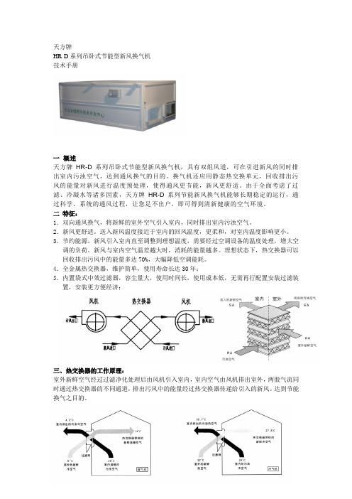
天方牌HR-D系列吊卧式节能型新风换气机技术手册一概述天方牌HR-D系列吊卧式节能型新风换气机,具有双组风道,可在引进新风的同时排出室内污浊空气,达到通风换气的目的。
换气机还应用静态热交换单元,回收排出污风的能量对新风进行温度预处理,使得通风更节能,新风更舒适。
由于全面考虑了过滤、冷凝水等诸多因素,天方牌HR-D系列节能新风换气机能够长期稳定的运行,通过科学、系统的通风过程,让您足不出户,即可得到清新健康的空气环境。
二特征:1.双向通风换气,将新鲜的室外空气引入室内,同时排出室内污浊空气。
2.新风更舒适。
送入新风温度接近于室内的回风温度,更柔和,对室内温度影响更小。
3.节约能源。
新风引入室内直至调整到理想温度,需要经过空调设备的温度处理,增大空调的负荷。
新风与室内空气温差越大时,消耗的能量越多。
理想状态下,热交换器可以回收排出污风中的能量多达70%,大幅降低空调能耗。
4.全金属热交换器,维护简单,使用寿命长达30年;5.内置袋式中效过滤器,容尘量大,使用时间长,使用成本低,无需再行配置安装过滤装置,安装更方便经济;三、热交换器的工作原理:室外新鲜空气经过过滤净化处理后由风机引入室内,室内空气由风机排出室外,两股气流同时通过热交换器的不同通道,排出污风中的能量经过热交换器传递给引入的新风。
达到节能换气之目的。
五、结构尺寸图表:02D/04D/08D/15D/25D 图表35L/50L 图表七如何安装用户应委托专业的暖通工程师进行工程设计,并聘请有经验的施工单位工程施工。
设计和施工应考虑设备本身的技术参数,按照国家有关规范进行。
同时,设备安装时需满足以下要求:1.安装应确保室内外进出风口无障碍物,且室内与室外的新风与排风风口间的间距保持1m以上;2.使新风换气机远离热源和易燃气体3.设备固定到位后,应对每个排水管口连接排水管,并分别进行水封处理为佳。
(35L\50L自带水封注水口,使用前从注水口将水注入,直至排水口向外流水即可。
【优质】tcl空调说明书word版本 (4页)

本文部分内容来自网络整理,本司不为其真实性负责,如有异议或侵权请及时联系,本司将立即删除!== 本文为word格式,下载后可方便编辑和修改! ==tcl空调说明书篇一:TCL空调说明书 -扫描件篇二:TCL空调故障代码篇三:TCL空调遥控器企业标准TCL空调器(中山)有限公司企业技术标准QT/TK-01.26-201X遥控器201X-05-30批准 201X-06-01实施TCL空调器(中山)有限公司发布企业标准文件名称:遥控器文件编号: QT/TK-01.26-201X起草部门:设计开发部品质管理部版本: A编制:李怀陈声艺日期: 201X 年 05 月 25日标准化:杨汉东日期: 201X 年 05 月 25日审核:黄永毅招伟日期: 201X 年 05 月 25日审批:刘锋欧阳新桥日期: 201X 年 05 月 25日批准:郑双名日期: 201X 年 05 月 30日说明本技术标准为TCL空调器(中山)有限公司所有,未经许可任何人不得翻印,纸介文件在盖上红色受控印章后方为有效!1 范围本标准规定了TCL空调器用红外遥控发射器(简称:遥控器)的技术要求、试验方法、检验规则、标志、包装、运输及储存等。
本标准适用于所有TCL空调器所用的遥控器。
2 引用标准GB/T2423.1电工电子产品环境试验第2部分:试验方法试验A:低温GB/T2423.2电工电子产品环境试验第2部分:试验方法试验B:高温GB/T2423.3电工电子产品基本环境试验规程试验Ca:恒定湿热试验方法GB/T2423.22 电工电子产品环境试验第2部分: 试验方法试验N:温度变化GB/T2423.10 电工电子产品环境试验第2部分:试验方法试验Fc和导则:振动(正弦)GB4343.2 电磁兼容家用电器、电动工具和类似器具的要求第2部分:抗扰度产品类标准GB/T17626.2 电磁兼容试验和测量技术静电放电抗扰度试验 GB/T2828.1计数抽样检验程序 QB/T 2263 房间空气调节器电子控制器QT/TK-08.001–201X《产品质量特性重要度分级、不合格(缺陷)分类及编码、不合格品分类导则》3 定义3.1 红外遥控发射器通过红外发射器件,发射被编码脉冲信号调制的红外光,在一定距离控制相应设备的有关功能的装置,称为红外遥控发射器,简称遥控器。
(完整word版)空调系统中PAU、MAU、AHU、DCC、RCU、DDCFCU的区别

空调系统中PAU、MAU、AHU、DCC、RCU、DDC FCU的区别AHU (Air Handle Unit)组合式空调箱:主要是抽取室内空气(return air) 和部份新风以控制出风温度和风量来并维持室内温度。
PAU(Pre-Cooling Air Handling Unit)预冷空调箱: Primary Air Unit对室外新风进行预处理,在送至风机盘管(FCU)。
RCU(Recycled airhandling unit)循环空调箱。
MAU(Make-up Air Unit)全新风机组:是提供新鲜空气的一种空气调节设备。
功能上按使用环境的要求可以达到恒温恒湿或者单纯提供新鲜空气。
工作原理是在室外抽取新鲜的空气经过除尘、除湿(或加湿)、降温(或升温)等处理后通过风机送到室内,在进入室内空间时替换室内原有的空气。
当然以上所提到的功能得根据使用环境的需求来定,功能越齐全造价越高。
DCC (Dry Cooling Coil) 干式冷却盘管:(简称为干盘管或干冷盘管)是用来消除室内的显热的。
DDC : (Direct Digital Control ) 直接数控制 HEPA (High efficiency particulate air Filter),中文意思为高效过滤器,达到HEPA标准的过滤网,对于0.1微米和0.3微米的有效率达到99.998%, HEPA网的特点是空气可以通过,但细小的微粒却无法通过。
它对直径为0.3微米(头发直径1/200)以上的微粒去除效率可达到 99.7%以上,是烟雾、灰尘以及细菌等污染物最有效的过滤媒介。
(抽烟产生的烟雾颗粒直径为0.5微米)它是国际上公认的高效过滤材料。
经广泛运用于手术室、动物实验室、晶体实验和航空等高洁净场所。
FCU (File Control Unit)风机盘管:Fan Control Unit风机盘管是空调系统的末端装置,其工作原理是机组内不断的再循环所在房间的空气,使空气通过冷水(热水)盘管后被冷却(加热),以保持房间温度的恒定。
空调箱手册(Word版)

美的[K]系列空调箱产品概述美的中央空调事业部自1999年创建以来,始终以“提供最佳环境温度解决方案”为宗旨,不论何时何地,都能为用户带来舒适、宜人的环境。
作为世界一流的专业的中央空调设备和服务供应商,美的中央空调在空调制冷领域中不仅拥有最精湛的技术、先进的制造工艺水平,而且锐意进取,不断创新,一直走在空调技术发展的前列。
MKSII系列是集美的多年空调箱设计及制造经验,进行多项改进和创新推出的一款适应市场需求的新型空气处理机组。
该系列产品经国家空调质量监督检验测试中心测试,具有噪声低、防漏风、断冷桥、结构紧凑等特点,性能达到国内先进水平,是中国制冷空调工业协会推荐使用产品。
作为舒适性空调,可广泛用于酒店、剧院、商场、办公楼、学校等各种场所;作为工业用空调,亦可满足电子、化工、医疗、制药、卷烟、食品、轻工等各行业的需要。
美的标准型空气处理机组由吊式、卧式、立式三大系列组成,处理风量从2000m3/h到40000m3/h。
机组特点内外分离,隔断冷桥机组框架和面板均采用内外分离式创新设计,中间通过高强度工程塑料连接,且在型材和面板内腔内充注高密度聚氨酯发泡(密度≥45kg/m3 ),完全隔断冷桥,可有效阻止机组冷量损失和外部凝露。
多重密封,防止漏风机组采用多重“阶梯式”结构,内外阶梯均设有密封措施,再加上负压式设计,可确保机组漏风率极低,漏风率≤0.29%,仅为国家标准规定的1/10,更无漏水滴水之虞。
超低噪音,安静运行知名品牌风机,机组所用的风机型号经专业软件选型确定,确保最佳工况点和出口风速,保证管路中良好的空气流动状态,减少运行噪声。
高效换热,性能优良机组换热器采用优质开窗式铝鳍片,交错排列,再加上多种流路优化设计,兼顾了更高的换热效率和更低的液侧阻力。
外形美观,抗腐防损机组连接处为圆弧结构,外面板为优质彩钢板,防腐又美观,同时采用覆膜结构,有效防止在组装及运输过程中损伤面板。
拼装结构,维护方便拼装结构,易于现场组装和拆卸维护,同时保证箱体密封度和强度。
空调安装手册说明书
MANUAL DE INSTALACIÓNAIRE ACONDICIONADO TIPO INVERTERÍNDICEPRECAUCIONES DE SEGURIDAD (04)ESPECIFICACIONES Y ACCESORIOS (06)RESUMEN SOBRE LA INSTALACIÓN DE LA UNIDAD INTERIOR (07)PARTES DE LA UNIDAD (09)INSTALACIÓN DE LA UNIDAD INTERIOR (10)5.1 SELECCIÓN DE LA UBICACIÓN DE INSTALACIÓN (10)5.2 FIJAR EL SOPORTE DE PARED (11)5.3 PERFORAR LA PARED PARA COLOCAR LAS TUBERÍAS DE CONEXIÓN (12)5.4 PREPARACIÓN DE LA TUBERÍA DEL REFRIGERANTE (14)5.5 CONEXIÓN DE LA TUBERÍA DE DESCARGA (16)5.6 CONEXIÓN DEL CABLE DE COMUNICACIÓN (19)5.7 SUJECIÓN DE TUBERÍAS Y CABLES (21)5.8 MONTAJE DE LA UNIDAD INTERIOR (22)INSTALACIÓN DE LA UNIDAD EXTERIOR (24)6.1 SELECCIÓN DE LA UBICACIÓN DE INSTALACIÓN (24)6.2 INSTALACIÓN DE LA ARANDELA DE GOMA (26)6.3 FIJAR LA UNIDAD EXTERIOR (27)6.4 CONECTAR LOS CABLES DE COMUNICACIÓN Y DE ALIMENTACIÓN (28)INSTALACIÓN DE LA TUBERÍA DEL REFRIGERANTE (31)OBSERVACIONES SOBRE LA LONGITUD DE LA TUBERÍA (31)INSTRUCCIONES DE CONEXIÓN - TUBERÍA DEL REFRIGERANTE (31)7.1 CORTE DE TUBERÍAS (31)7.2 ELIMINACIÓN DE REBABAS (32)7.3 EXTREMOS ABOCARDADOS DE LA TUBERÍA (32)7.4 CONEXIÓN DE LAS TUBERÍAS (34)PURGA DE AIRE (37)INSTRUCCIONES SOBRE LA PURGA (37)OBSERVACIONES SOBRE LA CARGA DE REFRIGERANTE ADICIONAL (39)VERIFICACIONES ELÉCTRICAS Y DE FUGAS DE GAS (40)PRUEBA DE FUNCIONAMIENTO (41)ELIMINACIÓN DE RESIDUOS (43)SoporteFig. 3.11Si va a instalar una unidad sobre el suelo o sobre una plataforma de hormigón, realice lo siguiente:1. Marque las ubicaciones sobre la superficie para colocar cuatro pernos de anclaje para concreto según las especificaciones del cuadro de dimensiones para el montaje de la unidad.2. Realice una perforación para insertar los pernos.3. Limpie el polvo de los agujeros.4. Coloque una tuerca en el extremo de cada perno.5. Martille los pernos en los agujeros previamente perforados.6. Extraiga las tuercas de los pernos y coloque la unidad exterior sobre los pernos de anclaje.7. Coloque una arandela en perno, y luego las tuercas.8. Usando una llave, apriete cada tuerca hasta el tope.ADVERTENCIAAL PERFORAR EL HORMIGÓN, SE RECOMIENDA USAR SIEMPRE PROTECCIÓN OCULAR.Si va a instalar la unidad sobre un soporte de pared, realice lo siguiente:PRECAUCIÓNAntes de realizar la instalación de una unidad sobre la pared, asegúrese de que la pared esté hecha de ladrillos, hormigón o cualquier material de características similares. La pared debe ser capaz de soportar al menos cuatro veces el peso de la unidad.1. Marque las posiciones de los cuatro orificios del soporte , asegúrese que este cumpla con las especificaciones del cuadro de dimensiones para el montaje de la unidad.2. Realice una perforación para insertar los tornillos.3. Limpie el polvo después de realizar los agujeros.4. Coloque una arandela en el extremo de cada tornillo.5. Insertar los pernos de anclaje dentro de los agujeros realizados, coloque el soporte en su posición y golpee con un martillo los pernos en la pared.6. Compruebe que los soportes de montaje hayan quedado nivelados.7. Eleve la unidad cuidadosamente y coloque su base sobre los soportes.8. Atornille la unidad firmemente a los soportes.REDUCIR VIBRACIONES DE LA UNIDAD MONTADA EN LA PAREDSi es posible, puede instalar la unidad para pared con un soporte de caucho para reducir las vibraciones y el ruido.6.4: Conectar los cables de comunicación y de alimentaciónLa bornera de la unidad exterior está protegida por una tapa en el lateral de la unidad. En la parte interior de la tapa se encuentra impreso un diagrama eléctrico general.ANTES DE REALIZAR TRABAJOS ELÉCTRICOS, LEA ESTAS REGLAMENTACIONES1. La instalación eléctrica debe cumplir con las reglamentaciones locales y nacionales vigentesy debe ser llevada a cabo por personal calificado.2. Las conexiones eléctricas deben ser realizadas de acuerdo a las especificaciones delComprobaciones de fugas de gasHay dos métodos diferentes para comprobar si hay fugas de gas.Método de agua y jabónCon un cepillo suave aplique agua jabonosa o detergente líquido en todos los puntos de conexión de las tuberías en la unidad interior y exterior. La presencia de burbujas indica que hay una fuga.Método del detector de fugasSi usa un detector de fugas, consulte el manual de uso del dispositivo para un mejor funcionamiento.LUEGO DE COMPROBAR SI HAY FUGAS DE GASDespués de confirmar que todas las conexiones NO tienen fugas, reinstale la tapa de la válvula en la unidad exterior.PRUEBA DE FUNCIONAMIENTOAntes de llevar a cabo la prueba de funcionamientoSólo realice la prueba de funcionamiento después de haber completado los siguientes pasos:• Comprobaciones de seguridad eléctrica: Confirme que el sistema eléctrico de la unidad sea seguro y funcione.• Comprobaciones de fugas de gas: Compruebe todas las conexiones de la tuerca abocardada y confirme que el sistema no tenga fugas.• Verifique que las válvulas de gas y líquido (de alta y baja presión) estén completamente abiertas.Instrucciones sobre la prueba de funcionamientoLa prueba de funcionamiento se debe realizar durante al menos 30 minutos.1. Conecte la unidad a la electricidad.2. Pulse el botón ON/OFF en el control remoto para encender el equipo.3. Pulse el botón MODE (Modo) para desplazarse a través de las siguientes funciones, una por vez:COOL (refrigeración): Seleccione la temperatura más baja posible.HEAT (calefacción): Seleccione la temperatura más alta posible.4. Deje que cada función permanezca activa durante 5 minutos y lleve a cabo los siguientes chequeos:。
- 1、下载文档前请自行甄别文档内容的完整性,平台不提供额外的编辑、内容补充、找答案等附加服务。
- 2、"仅部分预览"的文档,不可在线预览部分如存在完整性等问题,可反馈申请退款(可完整预览的文档不适用该条件!)。
- 3、如文档侵犯您的权益,请联系客服反馈,我们会尽快为您处理(人工客服工作时间:9:00-18:30)。
D
R
2.8 2.5 .05 5.8
1.5 42
4 0
4
5
2
2
6
2
R 70
7 2.9 1.5 .05 5.0
1
1
1
1
3
2 2.1 32
1010*1
6 000
5
6
2
2 20 .5 80 .5 00 .2
D
6
2 600*680
R
0.5 0.6 .42 7.4
3.5 60
048
4
6
2
2
1
1
1
1
3
2
6
2
1050*1
4
1
2
0
1
0
R
3 7.1 0.5 .82 5.2
30
6 000
2
2
0
2
D
R
0.1 6.5 .96 0.4
044
2
2
1
1
40 R 000 3.1 7.7 .10 2.6
5
9
9
0
1
0
1
0 6.2 8
900*85
0 .37 20 .37 80 .55
5
1 0*525
7.1 10
5
1
9
0
1
0
2
0 7.4 22
结构形式:D—吊式,W—卧式,
名义风量:( 80×100 m3/h ) 产品设计序列号 美的新型双壁空气处理机组
左右机型判断 面对机组进风方向(顺气流方向),接管及检修门在左侧为左机型,在右侧为右机
型。
5
6
7
机组性能参数表
吊式系列机组(回风工况)
额
机组 型号
MK S II-
定 风
量 m
3/h
额 定
4
7
8
3
3
1
R
1 0.7 4.8 .38 4.5
1
2
2
2
3
20Leabharlann 6 200081
4
3 30 .2 10 .2 60
D
R
9.5 08.6 .28 8.6
4
8
1
4
2
1
R
1 9.2 11.0 .27 1.4
1
50
6 5000
1
1
5
2 80
D
R
12.5 38.9 .38 3.5
2 3
60
4 3
10
请注意: 标准工 况
1010*9
0 .37 30 .37 00 .55
5
1 70*555
7.5 40
9
0
1
0
2
0
5
1
1010*1
0 .55 30 .55 00 .75 8.2 62 300*555
D
6
2
3
1
1
6
1
R
8.4 5.2 .36 8.5
0.1 73
4
3
3
1
1
0
R
5 0.5 6.8 .46 4.4
50
6 000
冷 量
k
W
额 定
热 量
k
W
冷水
流阻
量力
L
k
/s Pa
机 外
余 压Ⅰ
P a
电机电机电机
机外机外机组
功余功余功噪
率Ⅰ 压Ⅱ 率Ⅱ 压Ⅲ 率Ⅲ 声
k
P
k
P
k
d
W
a
W
a
W B(A)
机 组
重 量
k g
外形尺 寸 长*宽* 高
mm
4
1
1
0
1
0 R
2 2.1 4.9 .58 0.4
20
6 000
1
1
0
1
D
R
4.2 8.5 .68 2.5
3
4
1
1
D
R
7.1 3.9 .77 5.2
9
1
1
0
.1 30
1
2
.1 30
5
1
1 9.5 96
1010*1
.5
6
2 360*605
1.5 18
4
3
4
1
2
6
2
0R
6 4.8 3.6 .66 1.1
1
1
1
1
2
1 0.2 15
1010*1
60 6 000
4
5
2
2 20
.1
70
.1
70
.5
6
2 550*605
美的[K]系列空调箱
产品概述 美的中央空调事业部自 1999 年创建以来,始终以“提供最佳环境温度解决方案”为宗 旨,不论何时何地,都能为用户带来舒适、宜人的环境。作为世界一流的专业的中央空调 设备和服务供应商,美的中央空调在空调制冷领域中不仅拥有最精湛的技术、先进的制造 工艺水平,而且锐意进取,不断创新,一直走在空调技术发展的前列。 MKSII 系列是集美的多年空调箱设计及制造经验,进行多项改进和创新推出的一款 适应市场需求的新型空气处理机组。该系列产品经国家空调质量监督检验测试中心测试, 具有噪声低、防漏风、断冷桥、结构紧凑等特点,性能达到国内先进水平,是中国制冷空调 工业协会推荐使用产品。作为舒适性空调,可广泛用于酒店、剧院、商场、办公楼、学校等 各种场所;作为工业用空调,亦可满足电子、化工、医疗、制药、卷烟、食品、轻工等各行业 的需要。 美的标准型空气处理机组由吊式、卧式、立式三大系列组成,处理风量从 2000m3/h 到 40000m3/h。
高效换热,性能优良 2
机组换热器采用优质开窗式铝鳍片,交错排列,再加上多种流路优化设计,兼顾了 更高的换热效率和更低的液侧阻力。
外形美观,抗腐防损 机组连接处为圆弧结构,外面板为优质彩钢板,防腐又美观,同时采用覆膜
结构,有效防止在组装及运输过程中损伤面板。
拼装结构,维护方便 拼装结构,易于现场组装和拆卸维护,同时保证箱体密封度和强度。整机或散件 运输可选。
紧凑结构,节省空间 3
公司在保证产品性能的前提下,通过 CFD 优化设计使得机组结构更为紧凑,体积 小,机组高度超薄,可节省机房安装空间,亦专为吊顶设计。
4
型号说明 MKS II 080 D A — Z S L—余压Ⅲ
管,C—其它,如 8 排 L—立式
机外余压:S—余压Ⅰ,缺省—余压Ⅱ,
接管方式:Z—左接管,Y—右接管 换热器排数:A—4 排管,B—6 排
7
5
冷
回风制
21
—
60
—
热
◎机组噪声测试条件为:未通水机组接风管后,距机组各表面 1m 处测得的 声压级噪声平均值;
进风干球 温度(℃)
进风湿球 温度(℃)
进水温度 (℃)
进出水温 差(℃)
6
2
3.5 75
6
3
3.5 10
1100*1
3
6
3 900*785
5.2 40
6
3
5.5 35
1100*1
3
6
3 950*885
7.1 70
6
4
6.4 02
1250*2
4
6
4 350*910
8.2 45
10
回风制
27
19.5
80 R 000 9.2 0.1 .35 8.3 20 .5 80 .5 00 .2 3.4 51 800*680
9
D
6
6
7
2
3
R
0.2 2.2 .88 0.4
4
5
7
2
2
1R
1 8.5 0.2 .80 7.5
1
2
1
2
3
00
6 0000
7
8
3
3 30
.2
90
.2
40
D
R
1.5 4.6 .42 2.5
机组特点 内外分离,隔断冷桥
机组框架和面板均采用内外分离式创新设计,中间通过高强度工程塑料连接,且在 型材和面板内腔内充注高密度聚氨酯发泡(密度≥45kg/m3 ),完全隔断冷桥,可有效阻止 机组冷量损失和外部凝露。
多重密封,防止漏风 机组采用多重“阶梯式”结构,内外阶梯均设有密封措施,再加上负压式设计,可确 保机组漏风率极低,漏风率≤0.29%,仅为国家标准规定的 1/10,更无漏水滴水之虞。 超低噪音,安静运行 知名品牌风机,机组所用的风机型号经专业软件选型确定,确保最佳工况点和出 口风速,保证管路中良好的空气流动状态,减少运行噪声。