集束天线说明书
S5000系列手持定向天线数据手册说明书

S5000系列手持定向天线数据手册CN_01A产品综述定向天线常用于安全部门和无线电管理部门定位发射源和干扰源的查找,也可以应用于EMC测试、场强扫描、基站检测维护、变电站电力系统检测维护、汽车EMI检测、医疗设备辐射、伪基站检测设备等领域。
S5000系列手持定向天线,频率范围覆盖10MHz~8GHz,携带运输方便、操作简单快捷,适合外携测量。
天线套装包含三个不同频段的定向天线和一个内置宽带低噪声放大器的手柄;天线与手柄以盲插的方式配合,一体快速插拔转换,可实现垂直或水平极化方向信号的测试;单个天线也可以直接通过N型母头连接设备使用;手柄内置宽带低噪声放大器和可充电电池,设计有“直通”和“放大”两种工作模式以提高接收信号的动态范围;外接有N型公头稳相低损柔性射频线缆连接频谱仪使用。
型号与主要指标天线增益10dB(典型值)极化方向水平,垂直手柄射频线 1.5米/N型,公头包装尺寸470 x 400 x 240mm净重0.45kg(含手柄0.96kg)0.32kg(含手柄0.83kg)0.50kg(含手柄1.01kg)产品外观设计特色◆手柄带有放大或直通开关功能,适合测试时大信号与小信号环境的切换。
当按下放大开关时亮绿灯,信号经过LNA 放大处于有源放大工作状态,按下开关灭灯时信号直通处于无源工作状态。
◆手柄底部带有1/4 英寸接口方便上三脚架固定测试;充电接口为手柄内锂电池充电。
手柄上部为机械指北针。
◆天线支持快速插拔切换不同频段天线,利用塑料弹性和N 头接口进行卡位固定。
手柄和天线当插入深度到位后会听到“咔”声音证明已经插好,拔出方法反之。
快插拔时注意天线与手柄的对接平衡线对接,避免损坏N 头及使用寿命。
◆手柄充电时指示灯红灯处于充电状态,绿灯时处于饱和状态。
不使用时请关闭手柄放大开关处于灭灯无源状态。
◆射频线避免90°弯折。
◆实测增益图表典型方向图和应用图800MHz方向图3GHz方向图6GHz方向图频谱频率精确中频分析测量关于鼎阳鼎阳科技(SIGLENT)是通用电子测试测量仪器领域的行业领军企业。
集束天线技术规范书

中国移动通信有限公司2006年集束天线集中采购技术规范书中国移动通信有限公司二零零六年九月目录一总则 (1)二规范性引用文件 (5)三、质量管理与保障体系 (5)四、集束天线的示意说明和投标方实际工程集束天线图片 (6)五、集束天线主要性能指标及要求 (6)六、供货及验收 (4)七、服务 (5)八、技术资料和技术培训 (6)本技术规范书是中国移动通信有限公司就向其提供集束天线的投标人提出的技术要求,作为投标人制定技术应答书的依据。
一、总则1.对于本规范书提出的有关要求,投标人应在技术应答书中逐项答复,应答要求为“满足并优于”、“满足”、“部分满足”、“不满足”。
对于相关技术参数指标等内容,投标人应说明能否满足要求,并应答具体数值,同时应在投标文件中提供相应的测试报告或其他证明文件资料。
2.对于本规范书中未能提出的系统性能指标和不合理的功能配置,投标人应在建议书中加以补充说明,并提供有关详细资料。
3.投标人应根据招标项目的要求提出完整的设备配备和实施方案,如有缺漏,由投标人免费补足。
4.招标人有权在签定最终合同前,根据需要修改本规范书。
规范书的最终解释权在招标人。
5.本次招标仅限于室外基站用集束天线,不包括室内分布系统中所涉及的天线。
6.天线使用经验为本项目提供的集束天线类型必须是经过工程实际使用并通过竣工验收、同时必须是为一个以上电信运营商提供一年以上满意服务的集束天线类型。
2004-2005年(对中国移动)集束天线供货记录注:填报对中国移动各省(市)移动通信公司的集束天线供货记录。
2004-2005年(对其它电信运营商)集束天线供货记录表2注:只填报对中国联通的集束天线供货记录。
7.本技术规范书根据投标人的应答,经完善后将作为商务合同的附件之一。
8.采购清单集束天线按照内置天线的型号可分为以下类型:注:1.序号1-14项中每套集束天线应包含内置的3副天线、美化外罩、连接件、紧固件和天线抱杆。
2.序号15的电调便携式控制器(含雷电保护器)应能同时控制一个基站的三面天线,而且是能够多个基站通用的设备。
16M天线系统说明书

16m天线系统1 概述众所周知,天线伺服系统是卫星通信地球站中最庞大、最重要的设备之一。
它的作用是将通信设备发送的信号向卫星方向定向的辐射出去,同时接收来自卫星的信号。
整个天伺设备由天线和伺服跟踪两大部分组成。
随着卫星通信技术的发展,卫星通信地球站天线正向着多用途和高性能方向发展,其主要特点是采用了许多高新技术,如双频或多频段共用技术、多波束技术、移动卫星车载站技术、宽频带技术和高增益低旁瓣技术等。
54所研制的16m天线是一种赋型卡塞格仑双反射面天线,采用了高增益低旁瓣赋型和计算机优化设计等先进技术,通过优化天线的几何参数、赋型主副反射面和采用高性能宽频带的波纹喇叭,使得该天线具有高效率、低旁瓣、低交叉极化、低驻波比和高G/T值等优良性能。
该天线不仅电气性能优良,而且结构设计合理,抗风能力强,外形美观,跟踪精度高。
因此,该天线一投入使用就受到了用户的好评。
图1为天线的外观图。
图1 16m天线外观图16m天线主要由天线主副反射面、C波段馈源(波纹喇叭和微波网络)、天线反射体结构、方位——俯仰型座架、方位——俯仰驱动和同步装置、天线控制及驱动单元、跟踪接收机、波导和电缆馈线、安全保护装置和馈源口面除冰装置等组成。
2 结构特征与工作原理2.1 天线的组成16m天线主要由天线主副面、C频段馈源系统(波纹喇叭和微波网络)、副面支撑装置、馈源套筒、中心体(高频房)、辐射梁、天线座架、方位俯仰转动装置、天线驱动器、天线控制器、跟踪接收机、两路波导走线、馈源口面除冰化雪装置和避雷针等组成。
2.2 工作原理天线是一种发射和接收无线电波的设备。
天线的功能首先是能量转换:将发射机输出经传输线传输的射频导波能量转换成无线电波能量向空间辐射;反之,将入射空间电磁波能量转换成射频导波能量传给接收机。
天线的另一功用是实现特定极化波的定向辐射和接收,即具有特定的方向性和极化特性。
16m天线是赋型卡氏天线,其原理示意图如图2所示。
CommScope 天线安装说明书
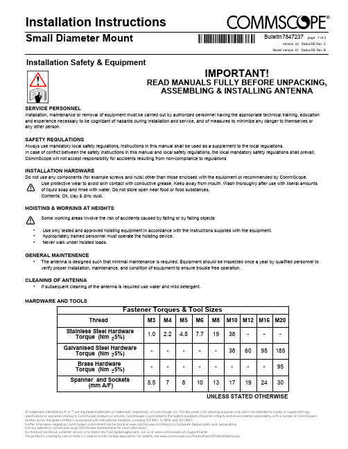
IMPORTANT!READ MANUALS FULLY BEFORE UNPACKING,ASSEMBLING & INSTALLING ANTENNASERVICE PERSONNELInstallation, maintenance or removal of equipment must be carried out by authorized personnel having the appropriate technical training, education and experience necessary to be cognizant of hazards during installation and service, and of measures to minimize any danger to themselves or any other person.SAFETY REGULATIONSAlways use mandatory local safety regulations, instructions in this manual shall be used as a supplement to the local regulations.In case of conflict between the safety instructions in this manual and local safety regulations, the local mandatory safety regulations shall mScope will not accept responsibility for accidents resulting from non-compliance to regulationsINSTALLATION HARDWAREDo not use any components (for example screws and nuts) other than those enclosed with the equipment or recommended by CommScope.Use protective wear to avoid skin contact with conductive grease. Keep away from mouth. Wash thoroughly after use with liberal amounts of liquid soap and rinse with water. Do not store open near food or food substances.Contents: Oil, clay & zinc dust.HOISTING & WORKING AT HEIGHTSSome working areas involve the risk of accidents caused by falling or by falling objects Use only tested and approved hoisting equipment in accordance with the instructions supplied with the equipment.• Appropriately trained personnel must operate the hoisting device.• Never walk under hoisted loads.•GENERAL MAINTENENCEThe antenna is designed such that minimal maintenance is required. Equipment should be inspected once a year by qualified personnel to •verify proper installation, maintenance, and condition of equipment to ensure trouble free operation.CLEANING OF ANTENNAIf subsequent cleaning of the antenna is required use water and mild detergent.•All trademarks identified by ® or ™ are registered trademarks or trademarks, respectively, of CommScope, Inc. This document is for planning purposes only and is not intended to modify or supplement anyspecifications or warranties relating to CommScope products or services. CommScope is committed to the highest standards of business integrity and environmental sustainability, with a number of CommScope’s facilities across the globe certified in accordance with international standards, including ISO 9001, TL 9000, and ISO 14001.Further information regarding CommScope’s commitment can be found at /About-Us/Corporate-Responsibility-and-Sustainability .Visit our website or contact your local CommScope representative for more information.For technical assistance, customer service, or to report any missing/damaged parts, visit us at: /SupportCenterThis product is covered by one or more U.S. patents or their foreign equivalents. For patents, see /ProductPatent/ProductPatent.aspxInstallation Safety & EquipmentHARDWARE AND TOOLSUNLESS STATED OTHERWISEInstallation Instructions02RE C page 1 of 2Small Diameter MountStatus Rev Version Model Version Status Rev Bulletin 01RE B7847237Fastener Torques & Tool SizesThreadM3M4M5M6M8M10M12M16M20Stainless Steel HardwareTorque (Nm 5%) 1.0 2.2 4.57.71938---Galvanised Steel HardwareTorque (Nm 5%)-----386095185Brass Hardware Torque (Nm 5%)--------95Spanner and Sockets(mm A/F)5.57810131719243002RE C page 2 of 2Small Diameter MountStatus Rev Version Model Version Status Rev Bulletin 01RE B7847237。
CommScope 5G 双口小型基站天线说明书
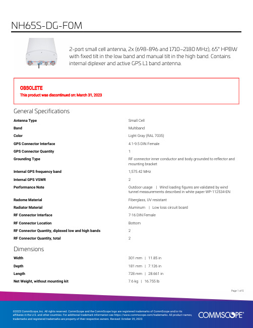
2-port small cell antenna, 2x (698-896 and 1710–2180 MHz), 65° HPBWwith fixed tilt in the low band and manual tilt in the high band. Containsinternal diplexer and active GPS L1 band antenna.OBSOLETEThis product was discontinued on: March 31, 2023General SpecificationsAntenna Type Small CellBand MultibandColor Light Gray (RAL 7035)GPS Connector Interface 4.1-9.5 DIN FemaleGPS Connector Quantity1Grounding Type RF connector inner conductor and body grounded to reflector andmounting bracketInternal GPS frequency band1,575.42 MHzInternal GPS VSWR2Performance Note Outdoor usage | Wind loading figures are validated by windtunnel measurements described in white paper WP-112534-EN Radome Material Fiberglass, UV resistantRadiator Material Aluminum | Low loss circuit boardRF Connector Interface7-16 DIN FemaleRF Connector Location BottomRF Connector Quantity, diplexed low and high bands2RF Connector Quantity, total2DimensionsWidth301 mm | 11.85 inDepth181 mm | 7.126 inLength728 mm | 28.661 inNet Weight, without mounting kit7.6 kg | 16.755 lb15Page ofElectrical SpecificationsImpedance50 ohmOperating Frequency Band1710 – 2180 MHz | 698 – 896 MHzPolarization±45°Electrical SpecificationsFrequency Band, MHz698–806806–8961710–18801850–19901920–2180 Gain, dBi10.110.51414.114 Beamwidth, Horizontal,degrees6965606061Beamwidth, Vertical, degrees39.935.714.113.513.1 Beam Tilt, degrees000–160–160–16 USLS (First Lobe), dB1515121313Front-to-Back Ratio at 180°,dB2432242525Isolation, Cross Polarization,dB2525252525VSWR | Return loss, dB 1.5 | 14.0 1.5 | 14.0 1.5 | 14.0 1.5 | 14.0 1.5 | 14.0 PIM, 3rd Order, 2 x 20 W, dBc-153-153-153-153-153Input Power per Port,maximum, watts125125125125125 Electrical Specifications, BASTAFrequency Band, MHz698–806806–8961710–18801850–19901920–2180 Gain by all Beam Tilts,average, dBi9.510.113.513.813.6Gain by all Beam TiltsTolerance, dB±1.3±0.8±0.7±0.5±0.6Gain by Beam Tilt, average, dBi 0 ° | 14.08 ° | 13.516 ° | 12.90 ° | 14.28 ° | 13.816 ° | 13.30 ° | 14.08 ° | 13.616 ° | 13.3Beamwidth, HorizontalTolerance, degrees±7.5±4.6±5.1±5.4±7.7Beamwidth, VerticalTolerance, degrees±6±3.2±1.1±0.7±0.8USLS, beampeak to 20° abovebeampeak, dB121313Front-to-Back Total Power at180° ± 30°, dB19202120191617181616Page of25CPR at Boresight, dB1617181616 CPR at Sector, dB959910 Mechanical SpecificationsWind Loading @ Velocity, frontal98.0 N @ 150 km/h (22.0 lbf @ 150 km/h)Wind Loading @ Velocity, lateral77.0 N @ 150 km/h (17.3 lbf @ 150 km/h)Wind Loading @ Velocity, maximum188.0 N @ 150 km/h (42.3 lbf @ 150 km/h) Wind Loading @ Velocity, rear99.0 N @ 150 km/h (22.3 lbf @ 150 km/h)Wind Speed, maximum241 km/h (150 mph)Packaging and WeightsWidth, packed409 mm | 16.102 inDepth, packed299 mm | 11.772 inLength, packed976 mm | 38.425 inWeight, gross13.9 kg | 30.644 lbRegulatory Compliance/CertificationsAgency ClassificationISO 9001:2015Designed, manufactured and/or distributed under this quality management systemREACH-SVHCCompliant as per SVHC revision on /ProductComplianceIncluded ProductsBSAMNT-3–Wide Profile Antenna Downtilt Mounting Kit for 2.4 - 4.5 in (60 - 115 mm) OD round members.Kit contains one scissor top bracket set and one bottom bracket set.* FootnotesPerformance Note Severe environmental conditions may degrade optimum performancePage of35Wide Profile Antenna Downtilt Mounting Kit for 2.4 - 4.5 in (60 - 115 mm)OD round members. Kit contains one scissor top bracket set and onebottom bracket set.Product ClassificationProduct Type Downtilt mounting kitGeneral SpecificationsApplication OutdoorColor SilverDimensionsCompatible Diameter, maximum115 mm | 4.528 inCompatible Diameter, minimum60 mm | 2.362 inWeight, net 6.2 kg | 13.669 lbMaterial SpecificationsMaterial Type Galvanized steelPackaging and WeightsIncluded Brackets | HardwarePackaging quantity1Weight, gross 6.4 kg | 14.11 lbRegulatory Compliance/CertificationsAgency ClassificationCE Compliant with the relevant CE product directivesCHINA-ROHS Below maximum concentration valueISO 9001:2015Designed, manufactured and/or distributed under this quality management systemREACH-SVHC Compliant as per SVHC revision on /ProductComplianceROHS CompliantUK-ROHS Compliant45Page ofPage of 55。
北京邦讯隐蔽天线产品手册a概要

北京邦讯隐蔽天线产品手册一体化隐蔽天线类隐蔽外罩类杆塔类北京邦讯技术有限公司2009年7月目录前言 (3第一部分一体化隐蔽天线类 (4一、集束型隐蔽天线(一体化及辅材 (4二、路灯型隐蔽天线(一体化 (6三、草坪灯型隐蔽天线(一体化 (7四、射灯型隐蔽天线(一体化 (8五、壁挂广告牌型隐蔽天线(一体化 (9六、壁画型隐蔽天线 (10七、壁挂型隐蔽天线 (11八、吸顶灯型隐蔽天线 (12第二部分隐蔽外罩类 (13一、变色龙型隐蔽外罩 (13二、方柱型隐蔽外罩及辅材 (141、方柱型隐蔽外罩 (142、方柱钢架隐蔽辅材: (15三、圆柱型隐蔽外罩及辅材 (161、圆柱型隐蔽外罩 (162.圆柱钢架隐蔽辅材 (17四、空调型隐蔽外罩及辅材 (171、空调型隐蔽外罩 (172.空调钢架隐蔽辅材: (18五、水箱型隐蔽外罩及辅材 (191、水箱型隐蔽外罩 (192.水箱钢架隐蔽辅材 (20六、水塔型隐蔽外罩及辅材 (211.水塔型隐蔽外罩 (212.水塔钢架隐蔽辅材 (22七、集束型隐蔽外罩及辅材 (23八、指示牌型隐蔽外罩 (24九、广告牌型隐蔽外罩 (25十、标示牌型隐蔽外罩 (26十一、空调型隐蔽外罩 (27第三部分杆塔类 (28高杆灯型 (29前言随着人们对生活小区环境要求的日益提高,城市建设和小区建设对隐蔽天线产品市场的需求也有了更高的要求,我公司为满足快速发展的市场需求,不断推陈出新。
为方便广大用户选型,特别编制了《北京邦讯隐蔽天线常用产品选型手册》。
本册将隐蔽天线产品主要分为基站美化类和小区美化类,隐蔽辅材作为隐蔽外罩的附属材料,跟随在相应的美化天线产品后面。
对于影响隐蔽天线产品整体安全性的产品结构、基站及防雷系统两方面,我公司均通过了权威部门的审核和通过。
隐蔽天线审核等级说明:隐蔽天线整体安全性主要包括产品结构、基础及防雷系统两方面,为保证选用的隐蔽天线量产产品工程可行性,确保整个隐蔽项目的安全可靠性,特将设计方案审核的权限规定如下:审核等级审核权限C 隐蔽天线结构工程师/天馈隐蔽天线结构工程师审核B 天馈隐蔽天线结构工程师审核A 具备甲级或乙级资质的建筑设计院审核第一部分一体化隐蔽天线类一、集束型隐蔽天线(一体化及辅材 1、集束型隐蔽天线(一体化型号详细指标频段范围增益方位角倾角尺寸 (单位:mm 审核等级 (直接落地安装 JZJS-065R15DB (1-V 824~960824~870:14.5 870~960:15 固定间隔120°机械下倾角固定电调:0~14º ¢600×1700-2100 C JZJS-065R15DD (1-V 824~9601710~1880 824~960:14.5 1710~1880:17 固定间隔120°机械下倾角固定 824~960电调:0~14º1710~1880电调:0~8º¢600×1700-2100 C JZJS-ODV065R15B17K (6 824~960 1710~2170 824~960:14.5 1710~2170:16.5 固定间隔120°机械下倾角固定824~960电调:0~14º1710~2170电调:0~7º¢600×1700-2100 C JZJS-065R1DK (3-V 1710~2170 1710~1850:171850~1990:17.51990~2170:18 固定间隔120°机械下倾角固定电调:0°~8° ¢600×2500 C说明:1安装方式:a该产品已经内置三扇区辐射单元,一般安装于建筑楼顶;b产品可直接安装,或选购各种高度的钢杆隐蔽辅材配用,也可与高杆灯配合使用。
Magnum Dynalab室内FM天线说明书

T H E E-Z I N E F O R F R U G A L A U D I O E N T H U S I A S T S Affordable $$AudioIssue Number 45: September 2009Magnum Dynalab Indoor FM Antenna'sBy Anthony Nicosia**********************************SpecificationsSR-100 Silver Ribbon Tunable FM AntennaAn indoor Antenna for both enhanced FM performance and HDTV broad-castsSpecificationsBase measures 3.5” width x 2.5” deep x 3/4” highMaximum height of antenna fully extended: approx. 37.5”Maximum width of antenna fully spread: approx. 32”Cord is approx. 3' longWarranty: twenty four month limited warranty applies to the first end userPrice: $35MD-205 Signal Sleuth FM signal AntennaAccording to Magnum Dynalab “In an independent test, using a commer-cially available FM tuner, the following percentile improvements were at-tained with the SLEUTH on line:Sensitivity (under 1dB limiting) -170%Spurious Response Rejection -90%Image Rejection -380%Ultimate Sensitivity was rated at 70dB+Also, the total harmonic distortion (THD) re-mained unchanged indicating the Sleuthadded no measurable distortion of its own.”SpecificationsCircuit: 3 varactor-tuned RF stagesGain: VARIABLE -30dB thru +30dBTuning Range: 88-110 MHzBandwidth: Better than 400KHzNoise: Less than 4dBDistortion: 0%Antenna Input: 75 ohmsPower Required: 230/240/110 voltsSize: 17” x 1.75' x 6”43.18cm x 4.45cm x 15.24cmWeight: 6 lbs/ 2.65KGWarranty: twenty four month limited warranty applies to the first end userPrice: $435Company InformationMagnum Dynalab Ltd.8 Strathearn Avenue, Unit 9Brampton, OntarioCanadaL6T 4L9Telephone: (905) 791-5888Toll free in North America 1-800-551-1430Fax: (905) 791-5583International Fax: (1) (905) 791-5583US Contact Telephone, toll free: 1-800-551-4130Web address: Email address: **********************L ooking back twenty-five years ago to 1984, we see a time when Magnum Dynalab introduced its very first product, the Signal Sleuth, which was designed to boost and stabilize FM signals. According to Larry Zurowski, the president of Magnum Dynalab, the biggest difference between that Signal Sleuth and today’s model is that the gain curve is now more consistent across the FM band. Later, in September of 1985, the company marketed the FT 101, which was her-alded as their first FM tuner. Magnum Dynalab now makes FM tuners, an integrated FM receiver, an integrated ampli-fier as well as a selection of both indoor and outdoor antennas. Having recently, in the June 2009 issue of “AffordableAudio”, taken a look back at the 1960's McIntosh MR67 tube tuners I can only wish I’d had today’s Magnum Dynalab products around to help with the review.I have, as of late, been using a TERK FM+ Indoor Antenna, which was recommended to me by a friend. Unfortunately, I live in a more difficult environment than his, and while this inexpensive antenna priced at only $9.99 worked better than no antenna it still left me with a desire for something more substantial. When I first contacted Larry Zurowski I was completely upfront with him in explaining that I lived in an area that has great difficulty getting a proper reception. I explained that I am situated at the bottom of a very high steep hill where FM reception is poor, even when it comes to capturing local stations. Add this to the fact that there are large commercial planes flying relatively low, from the San Francisco airport, and you have an FM reception nightmare. Larry never addressed this issue, but rather sent me an email saying he would send the requested products as soon as he could get me an SR-100 Silver Ribbon Tunable FM Antenna, which were at the time on backorder. A few weeks latter both the SR-100 and Signal Sleuth arrived neatly packaged and in perfect condition.To tell you the truth I did not expect very much in the way of an improvement with the SR-100 antenna as I was al-ready using an indoor antenna for my MR-67 tuner. Having tried a variety of other indoor style antennas I never did have much luck picking up stations and was resigned to the fact that I must go the outdoor antenna route. After all this was only a thirty-five dollar investment, how much of a difference would it make being that I live in a difficult FM recep-tion area? As it turned out, it made a huge difference. I was floored with the vast improvement this indoor antenna made and had to put my own antenna back in just to see if maybe the moon and stars were aligned differently that day and had somehow cleared the skies for superior FM reception. But no, switching back to my original antenna resulted in a poorer performance once again that allowed for some stations to drift and others to be difficult to pull in properly. After reinserting the SR-100 I found everything to be right once again. I was sold and spent the rest of the morning listening to music via my newly revamped FM tuner setup. With the SR-100 I was able to pull in stations that before were “edged” with static but now were quite silent. I felt a greater depth to the music as this silent background now af-forded me a clearer window with which to hear through, and I enjoyed each musical performance anew. Whereas be-fore I would glide the tuning knob through the various frequencies to hear plenty of static, now for the most part there was silence. It was not so much that it pulled in stations that I could not capture before but rather for me it made the stations I was already receiving sound clearer and more powerful. I liked what it brought to my system as it quite sim-ply did the job it was intended to accomplish and did so for the paltry sum of only thirty-five dollars. Having had other “rabbit ear” style antennas in my listening room before, I must say that my wife finds them quite unattractive, but not so with the SR-100. Its combination of mostly black and silver (an Oakland Raiders fans delight, yes we live less than an hour from their stadium) coupled with its slender simple appearance worked just fine for us from an aesthetics point of view.OperationNow in steps Magnum Dynalab's MD-205 Signal Sleuth FM signal Antenna. Take note that the Sleuth’s performance will be directly related to the quality of the antenna attached, as well of course as the reception within the area and the attributes of the tuner used in conjunction with it. It is a tunable RF processor for FM stations across the 88-108 MHZ frequency bandwidth. I naturally used Magnum Dynalabs own SR-100 Silver Ribbon antenna for this evaluation but as previously stated you might even want to try one of their more powerful outdoor antennas for a more “startling” experi-ence. I say startling because that is what this combination of SR-100 and MD-205 felt like to me. For a complete in-structional aide of how to set-up the MD-205 please read the owners manual, but for now let me give you a quick summation of the process which may at first seem a little complicated. With your purchase you will be supplied with a patch cord with 'F' connectors on both ends. Connect the FM tuner to the MD-205 via this patch cord to the area marked “Output to Tuner”. Connect the MD-205 to your antenna by way of the connector labeled “Antenna Input”. Please make sure that both switches located on the front of the MD-205 one labeled “Power”, is in the off position, the other “Antenna Signal”, is in the Bypass position. The FM tuner should also be turned off. Now use the supplied fac-tory power cord to plug the unit into an outlet. Be very careful as “Significant damage will be done to the unit if the wrong voltage is applied”. Appropriate voltage should be marked on the back of the unit. Alright, now turn on the MD-205 by moving the power switch to the “ON” position and then switch the antenna signal switch to the “Amplify” posi-tion making sure that all the LED lights turn on with each flip of the switch. Now that it is connected and functioning properly let me explain how to use the Sleuth when dialing in different radio stations, in order to help you tune them in for better reception.The following should be performed with the tuner's Mute switched “OFF” and the Sleuth's RF Gain control fully turned in the counter-clockwise position past where a 'click' is heard. First turn on the Sleuth with the Antenna Signal switch set to bypass, then turn on your FM Tuner. Make sure that the tuner is set to stereo. Tune to a station that has a fairly strong signal in your area and then set the Sleuth's tuning control to the same approximate frequency. There is no digi-tal readout for this, so you have got to trust what we used to do before digital readout, look with your own eyes and listen with your own ears. Now you can switch the Antenna Signal switch to the 'Amplify' position. As you then rotate the RF Gain control to fully clockwise and you will start to feel a click. Looking at the signal strength on the tuner you will rotate the Sleuth's Tune control until you find the highest reading on the signal strength meter, or until you perceive the clearest audio signal. Switching back to the RF Gain control, now rotate it counterclockwise until you get a weaker signal and then rotate it back clockwise until the audio signal is at its optimum. It is now time to turn the Mute switch to the 'ON' position. When you need to switch frequencies on your tuner simply turn the Antenna switch on the Sleuth to the 'bypass' position then tune your FM Tuner to the next desired station. Turn the Sleuth to the corresponding fre-quency, turn the Antenna switch back to amplify and rotate the Gain control and the Tuning Knob on the Sleuth to re-gain optimal signal strength or until it sounds best to your own ears.ImpressionsOnce again this Magnum Dynalab product impressed me with its ability to do exactly what it was designed for. It sepa-rated weaker stations by allowing you to finely tune them in and then boosted their signal with up to 30dB of gain, thereby adding power to the selected frequency. The affects of the Sleuth reminded me of a Vinyl pressed Master Re-cording where music would seem to spring forth from a background of dead silence, quite impressive indeed. As the Sleuth tuned in radio station after station, using the units gain control knob to put on the finishing touches, I was al-ways amazed at how the stations snapped into focus allowing me to hear music as if I had purchased a much more expensive tuner. The only two regrets I had concerning my review of the Sleuth were that I was not using one of their outdoor antennas, to see how good my MR67 tuner could actually be, and secondly that I was not using a modern day tuner made by Magnum Dynalab.ConclusionBoth the SR-100 Silver Ribbon antenna and the MD-205 Signal Sleuth FM signal Antenna added no coloration of their own to the sound, yet they did have an enormous affect on the musical performances heard through them. I suggest that both be used together in order to realize the full potential of each. The SR-100's job is to capture local FM radio stations and is an excellent alternative for audiophiles who do not want to install an outdoor antenna or those of us on a more stringent budget. It is tunable, to maximize FM reception, and, as my wife and I found, quite attractive. The Sleuth on the other hand is a device designed to tune in the weaker FM radio stations in your area, separate them from the stronger ones and add up to a 30dB boost of gain to the appropriate signal. While it is in itself no substitute for a good tuner or antenna it will enhance their performance by its ability to add three RF stages and power to the signal. Using them both together I found the quality of my FM reception vastly expanded while my listening pleasure increased immeasurably. FM broadcasts tuned in easily and the added background silence was indeed a welcome addition. Both products are very highly recommended.The Listening Environment:The review room is eighteen feet eight inches long by thirteen feet wide. The loudspeakers and equipment are kept on the short wall. The cathedral ceiling starts at eight feet and sloops upwards to thirteen feet at its peak in the middle spanning across the short length of the room for the full thirteen feet height. The hardwood floor has a nine by six foot oriental rug lying down the long ways toward the system placed dead center in between, yet not under, the listener and the review equipment The room has no doors, but has two openings. One is in front of the right Legacy Focus 20/20 loudspeaker, which gives access to the hallway while the other is behind the listening position and opens to the formal dinning area. The room is treated with two floor standing acousti-cal panels, one behind each speaker, and the audio equipment is located in a Cherry Synergy Twin S30 Salamander audio rack against and in the middle of the short wall. I have two power conditioners that plug into a PS Audio Power Port receptacle located behind the audio rack. There are also two Blue Circle Audio MKIII Power Line Pillows, one on each of two outlets on the long walls next to and behind each loudspeaker. The Legacy speakers are located about six feet seven inches from the rear wall to their front panel. They are also twenty one inches from the rooms side walls to the middle of each loudspeakers. The Legacy's are twelve feet apart from each other to form a triangle with the listening position that is also angled at twelve feet from loudspeaker to listener. In the corner of each short wall behind the Legacy's are a pair of 1989 Klipsch Klipschorn loudspeakers that are some-times used for reviews. If the Klipsch loudspeakers are used I would then reposition the two acoustical panels to slightly behind the listening position one to the left and the other to the right of it.Review Equipment:McIntosh MR67 Tube Tuner and matching wood cabinet with slant legsMonarchy Audio SM-70 Pro power amplifiers (2 used in mono block configuration), Monarchy Audio M24 Preamplifier, Samsung HD-841 Cd/SACD/DVD Audio universal player, Oracle Delphi MK I turntable, Grace 707 tonearm and Denon DL-301MK II Moving Coil stereo cartridge, Whest Phonostage.20 + MsU.20 power supply(for Moving Coil or Moving Magnet cartridges)PS Audio power port receptacle, Two Blue Circle Audio Mk III power line conditioners, Acoustic Revive RTP-4 Series power con-ditionerm, Kimber Kable 4TC loudspeaker cable with matching jumper wires, Kimber Kable Hero and Tonik InterconnectsTek Line, PC-8 Signature power cords, two six foot lengths, Mr. Cable,The Musician power cord, a nine foot lengthMonarchy Audio AC-1 power cord, two six foot lengths, Cherry Synergy Twin S30 Salamander audio rack。
KH-5G-SMAJ-131MM 天线产品规格书说明书

产品规格书Product Specification产品名称: 天线产品型号: K H-5G-SMAJ-131MM 规格描述:5G ,SMA-J ,胶棒版 本 : A01日 期 : 2020/07/17客户承认Customer Approve:制 作drawing 审 核check 批 准approved 陈星 向金保贺俊驹客户确认/日期1.工程图纸Product Drawing深圳市金航标电子有限公司2.产品规格Product Specification射 频 性能 参 数频率范围(MHZ )824-960/1710-2680/ 3400-3600/4800-4900电压驻波比 ≤3.0 增益(dBi ) 3.0 辐射方式 全向 极化方式 垂直极化 输入阻抗(Ω) 50 最大功率(W )10机 械 性 能 参 数接口形式 SMA-J 天线长宽(MM )171*19.5环 境 参 数工作温度 -30℃~60℃ 工作湿度40~85%3.S11测试数据4.增益和效率测试数据5.可靠性试验报告项目测试条件规格储存环境在没有指定的情况下测试温度、湿度、气压如下:1.温度为-40℃~+85℃2.相对湿度为45%-85%3.气压为86kpa-106kpa电气机械性能正常高低温试验在70℃与-40℃之间进行5次循环,然后在正常条件下1-2H,检查外观质量。
尺寸应满足规定并应满足满足于机械、电气性能耐恒定湿热试验相对湿度95±3%,试验温度:40℃.持续2H作用后,试品取出后5min之内测定电气性能,试品在正常条件下1-2H,检查外观质量尺寸应满足规定并应满足满足于机械、电气性能振动试验振频范围10-55HZ,位移幅值:0.35MM,加速度幅值:50.0M/S,扫频循环次数:30次电气机械性能正常跌落试验1M高空按照互相垂直的轴方向自由跌落3次电气机械性能正常测试设备及原理1.测试设备:网络分析仪Network Analyzers :Agilent 8753D 5071B综合测试仪Communications Test Set: Agilent E5515C3D暗室测试系统 3D Chamber Test System:2.测试原理:。
- 1、下载文档前请自行甄别文档内容的完整性,平台不提供额外的编辑、内容补充、找答案等附加服务。
- 2、"仅部分预览"的文档,不可在线预览部分如存在完整性等问题,可反馈申请退款(可完整预览的文档不适用该条件!)。
- 3、如文档侵犯您的权益,请联系客服反馈,我们会尽快为您处理(人工客服工作时间:9:00-18:30)。
FA/D独立电调集束型(不分瓣)一体化美化天线
1632303-YJS-R001-HS
技术规格书
2013年8月
目录
一、产品指标 (3)
1.FA/D天线电气指标 (3)
2.权值系数 (5)
3.机械性能指标 (6)
4.配件说明 (6)
二、产品图片 (7)
三、结构说明 (8)
四、安装说明 (9)
五、维护说明 (11)
一、产品指标
1.FA/D天线电气指标
频率范围1880~1920MHz 2010~2025 MHz 2555~2635 MHz
结构参数
阵列排列形式直线
端口数目18
极化方式±45°
列间距45mm
接口类型N-Female
馈电位置底部
机械下倾0°
电路参数
电下倾角精度±1.0°
电下倾范围2°~12 °
输入阻抗50Ω
各单元端口驻波比≤1.5
同极化隔离度
2度下倾≥20dB 3度~6度下倾≥25dB 7度~12度下倾≥28dB
异极化隔离度
2度下倾≥25dB 3度~6度下倾≥28dB 7度~12度下倾≥30dB
内置合路器FA/D频段之间的隔离≥30dB 平均功率容限≥25W
≥25W 峰值功率容限≥250W
≥250W
校准参数
校准端口至各单元端口的耦合度-26±2 dB 校准端口到各单元端口幅度最大偏差≤0.7dB 校准端口到各单元端口相位最大偏差≤5°校准端口驻波比≤1.5
性能参数
单元波束
水平面半功率波束宽度100°±15 °90°±15 °65°±15 °增益≥13dBi ≥14dBi ≥15dBi 波束±60度边缘功率下降∕∕12±2dB 垂直面半功率波束宽度∕∕≥5°前后比≥21dB ≥21dB ≥23dB 交叉极化比(轴向)≥16dB ≥16dB ≥16dB 交叉极化比(±60)≥7dB
上旁瓣抑制∕∕≤-15dB
业务0°指向波束增益≥19dBi ≥20dBi ≥20.5dBi
波束0°指向水平面半功率波束宽度≤29°≤26°≤25°0°指向水平面副瓣电平≤-12dB ∕∕
±60°指向波束增益≥16.5dBi ≥16.5dBi ≥16.5dBi ±60°指向水平面半功率波束宽度≤32°≤32°≤23°±60°指向水平面副瓣电平≤-5dB ≤-5dB ≤0dB
0°交叉极化比(轴向)≥20dB ∕∕0°前后比≥26dB ∕∕
广播波束
水平面半功率波束宽度65°±5 °65°±5 °65°±5 °垂直面半功率波束宽度≥7 °≥6.5 °≥5 °视轴增益≥13dBi ≥14dBi ≥14.5dBi 视轴增益@φ=±60 处电平下降12±2dB 12±2dB 12±2dB 前后比≥26dB ≥26dB ≥26dB 交叉极化比(轴向)≥22dB ≥22dB ≥22dB 交叉极化比(±20°)≥20dB ∕≥22dB 交叉极化比(±60°)≥8dB
上旁瓣抑制≤-15dB
水平面方向图Horizontal pattern 垂直面方向图Vertical pattern
2.权值系数
下倾角度2°
广播波束频段参数端口1 端口2 端口3 端口4 端口5 端口6 端口7 端口8
30°F
幅度∣Ii∣0.4 1 1 0.4 0.4 1 1 0.4 相位(°)0 1 6 0 0 1 6 0 A
幅度∣Ii∣0.4 0.98 1 0.4 0.4 0.98 1 0.4 相位(°)0 2 6 1 0 2 6 1 D
幅度∣Ii∣0.35 1 1 0.35 0.35 1 1 0.35 相位(°)70 0 0 70 70 0 0 70
65°F
幅度∣Ii∣0.43 1 1 0.6 0.43 1 1 0.6 相位(°)0 -18 -10 178 0 -18 -10 178 A
幅度∣Ii∣0.44 1 1 0.54 0.44 1 1 0.54 相位(°)0 -20 -10 164 0 -20 -10 164 D
幅度∣Ii∣ 1 1 0.58 0.31 1 1 0.58 0.31 相位(°)0 -17 175 -24 0 -17 175 -24
下倾角度7°
30°F
幅度∣Ii∣0.4 1 1 0.4 0.4 1 1 0.4 相位(°)0 1 6 0 0 1 6 0 A
幅度∣Ii∣0.4 0.98 1 0.4 0.4 0.98 1 0.4 相位(°)0 2 6 1 0 2 6 1 D
幅度∣Ii∣0.35 1 1 0.35 0.35 1 1 0.35 相位(°)70 0 0 70 70 0 0 70
65°F
幅度∣Ii∣0.43 1 1 0.6 0.43 1 1 0.6 相位(°)0 0 0 -168 0 0 0 -168 A
幅度∣Ii∣0.44 1 1 0.54 0.44 1 1 0.54 相位(°)0 0 0 -178 0 0 0 -178 D
幅度∣Ii∣ 1 1 0.58 0.31 1 1 0.58 0.31 相位(°)0 -2 175 -21 0 -2 175 -21
下倾角度12°
30°F
幅度∣Ii∣0.4 1 1 0.4 0.4 1 1 0.4 相位(°)0 1 6 0 0 1 6 0 A
幅度∣Ii∣0.4 0.98 1 0.4 0.4 0.98 1 0.4 相位(°)0 2 6 1 0 2 6 1 D
幅度∣Ii∣0.35 1 1 0.35 0.35 1 1 0.35 相位(°)70 0 0 70 70 0 0 70
65°F
幅度∣Ii∣0.43 1 1 0.6 0.43 1 1 0.6 相位(°)0 15 0 -150 0 15 0 -150 A
幅度∣Ii∣0.44 1 1 0.54 0.44 1 1 0.54 相位(°)0 16 0 -161 0 16 0 -161 D
幅度∣Ii∣ 1 1 0.58 0.31 1 1 0.58 0.31 相位(°)0 16 157 -2 0 16 157 -2
3.机械性能指标
机械性能
集束型美化天线尺寸φ580*1950mm
内含天线数3面FA/D天线
水平可调角范围±15°(手调)
美化天线重量140KG
雷电保护直流接地
安装方式楼面基础、锚固安装
维护方式底部维护门
天线外罩材料玻璃钢厚度3-5mm
外罩表面处理白色烤漆
天线外罩抗老化保用10年
环境温度/极限温度-40°~+60°/-55°~+75°
相对湿度8%~98%
大气压70~106kpa
工作风速110km/h
摄冰厚度10mm不被破坏
天线罩材料阻燃性GB8624-1997难燃一级
防紫外线一年之内不变色
耐酸碱度两年之内无明显褪色
防水等级IP55
其他要求整体防腐、防锈
外露金属件(不锈钢除外)全部热镀锌;
4.配件说明
配件说明
M16外六角螺栓,平垫,弹垫,螺母各8pcs
标准配件
避雷针1PCS,吊环
楼面杆、普通螺丝、膨胀螺丝,3M长4芯集束跳线、3M长5芯集束跳线、可选配件
50M长控制电缆
二、产品图片
三、结构说明
避雷针
法兰底座
F A /D 相位中心
楼面杆/或其他连接杆
楼面杆组件高度天线与杆总高度楼面杆组件型号H1001000mm 2950mm H2002000mm 3950mm H3003000mm 4950mm H4004000mm 5950mm H5005000mm 6950mm H600
6000mm 7950mm H7007000mm 8950mm H8008000mm 9950mm H9009000mm 10950mm H1000
10000mm
11950mm
四、安装说明
一. 安装工具:
1.开口扳手30 2把;
2.十字螺丝刀 1把;
二. 安装步骤:
1.用8-M16*75螺丝将集束天线体下法兰和楼面杆连接好;
2.将避雷针安装在天线主体上部;
3.连接好各馈线;
4.调整好三面天线的方位角及下倾角;
5.安装完成。
(可以根据现场情况进行安装)
连接电缆示意图
-45°4芯集束接头 2555-2635MHz
法兰底座
F
A
/
D
相
位
中
心
楼面杆/或其他连接杆
+45°5芯集束接头
2555-2635MHz
-45°4芯集束接头 1880-1900MHz
2010-2025MHz +45°5芯集束接头 1880-1900MHz
2010-2025MHz
技术规格书五、维护说明
版本/版次:A/01 第11 页共11 页。