ECCC-71电磁搅拌对连铸板坯表面质量的改善
分析结晶器电磁搅拌对连铸坯质量的影响

分析结晶器电磁搅拌对连铸坯质量的影响摘要:连铸坯是炼钢炉炼成的钢水经过连铸机铸造后所得的产品。
其应用领域十分广泛,国内外在机械工程设备方面都在使用连铸坯制件。
其中,一些钢用的连铸坯可以直接轧钢,制成管、板、型钢等。
连铸坯在经过结晶器电磁搅拌后能够有效改善一些存在缺陷的地方。
基于此,本文对结晶器电磁搅拌、连铸坯概念以及相关实验进行简要分析。
关键词:结晶器;电磁搅拌;连铸坯引言:连铸坯中最关键的问题就是其中心偏析、夹杂物以及中心缩孔等严重影响铸坯的内部质量。
电磁搅拌是最常使用的连铸生产技术,它通过电磁力来优化消除结晶器内钢水过热度。
铸坯在经过电磁搅拌后其等轴晶率会有明显提高,从而得到良好凝固组织的铸坯,使得成品性能得到改善。
可以有效地解决连铸坯中心缩孔、纯净度等问题。
一、结晶器电磁搅拌及连铸坯概述连铸坯是钢水通过连续铸钢机铸成的钢坯。
连续铸钢技术可以把生产钢水到钢坯的整个过程进行简化,不需要经过初轧过程。
因此,连铸坯具备生产成本低、金属获得率高以及劳动条件好等一系列优点。
目前,连铸坯已是轧钢生产的重要原料。
然而,连铸坯也有一定的缺陷。
例如,一般疏松、中心疏松、锭型偏析、一般点状偏析、边缘偏析、皮下气泡、内部气泡、缩孔残余、翻皮、白点、轴心晶体裂缝、非金属夹杂物和心部裂纹等。
在低倍检验中会出现中心疏松、缩孔、中心偏析、表面角部裂纹、表面边部裂纹等缺陷。
电磁搅拌就是借助在铸坯的液相穴内感生的电磁力强化液相穴内钢水的运动,由此强化钢水的对流、传热和传质过程,从而控制铸坯的凝固过程,对提高铸坯质量具有积极的作用。
其中,结晶器电磁搅拌是目前最常见的、适用于各类连铸机的装置,它对改善铸坯表面质量、细化晶粒和减少铸坯内部夹杂及中心疏松等都有明显的作用。
一般情况下,为避免影响液面自动控制装置的使用,通常将其安装在结晶器的下部。
结晶器电磁搅拌的作用有以下几点:第一,改善铸坯表面质量。
铸坯在结晶器下面其表面呈现凝固的状态,此时可以将搅拌器置于结晶器的弯月面处,以起到对铸坯表面凝固开始前对其“清洗”的作用。
方坯电磁搅拌技术对连铸坯质量的影响--海口会议

为莱芜钢厂150³150方坯设 计制造的内置式电磁搅拌器
M-EMS两相低频电源
电磁搅拌水系统设计方案-150小方坯
电磁搅拌器采用独立的冷却系统,电磁搅拌器 冷却水系统由制纯水设备、水箱、水泵、过滤器、 换热器组成。
冷却水系统的安装情况: 冷却水系统的安装位置根据现场情况确定。
冷却水系统占地面积为:6³8㎡。
数据和图片由包钢技术中心提供
试验报告——82B轧坯纵断面低倍
a.无电磁搅拌
b.有电磁搅拌 152³152轧坯,熔炼号:3001924
数据和图片由包钢Βιβλιοθήκη 术中心提供试验结果——铸坯成分及成分偏析
Ø ý ÷¤ß Ð Ä ß ½ ò ¼ Ä ä ¯ Ñ Ö Å ³ ±Ö Ð Ï ²Ï Ì µ ±» 0.9 0.85
280³380大方坯组合电磁搅拌的生产实践
(1)为了提高包钢重轨280³380大方坯质量,在包钢原有跨 结晶器电磁搅拌的基础上,为包钢设计并制造了扇形段电磁搅 拌器 。 (2)第一次试验: 炼钢厂进行两种搅拌试验方案的两个浇次18 炉钢生产试验,钢种是U71Mn,断面是280³380mm,取试验 36块; (3)第二次试验: 钢种是U71Mn、断面是280³380mm,取试 验42块; (3)第三次试验: 钢种是82B,断面是280³380mm,取试样 52块。对轧出的152³152方坯取试样30块。 (4)试验中取电磁搅拌连铸坯和对比连铸坯试样(无电磁搅 拌)共160块,分别进行了硫印、低倍分析;对电磁搅拌连铸 坯和对比试样(无电磁搅拌)共41块,988个点,进行了C、S 、P、Mn的成分测定及铸坯偏析分析。
结晶器电磁搅拌对铸坯质量影响的研究
结晶器电磁搅拌对铸坯质量影响的研究张建新宋维兆(新疆八一钢铁集团有限公司)摘要:研究了电磁搅拌对中高碳钢铸坯组织和质量的影响,通过对搅拌强度的控制,改善了铸坯的表面质量,得到了良好的铸坯组织,减少了偏析、缩孔,提高了连铸坯质量.1前言电磁搅拌技术随着连铸技术发展和对连铸坯高质量的要求愈来愈来被广泛采用,电磁搅拌能有效的改善金属凝固组织,提高等轴晶率、减少缩孔级别、降低铸坯的偏析度等。
新疆八钢1999年建成一座70t直流电弧炉,主要生产的品种有:合金钢、中高碳钢、低合金结构钢和普钢,但以低合金结构钢和普钢为主。
为适应市场的需要及改变品种结构,2006年我们在小方坯连铸机上应用了结晶器电磁搅拌技术,该项技术的应用使铸坯质量得到了明显的改善。
2试验方案及方法2.1试验方案生产工艺流程为:70 t直流电炉一L F(70 t精炼炉)一CCM(R8合金钢连铸机)一轧钢。
实验钢种为55钢、65钢、60Si2Mn.方案为搅拌与不搅拌对比试验:对缩孔、碳偏析、皮下气孔及铸坯组织的影响。
连铸机主要参数见表l2.2试验方法 (1)在连铸机电磁搅拌结晶器上四流分别采用不同的频率、电流对钢水进行搅拌,在不同的温度、拉速下对铸坯截取试样。
(2)对截取的铸坯试样进行切割、车铣、磨光、酸洗。
作低倍检验研究电磁搅拌对缩孔、偏析和铸坯组织的影响。
(3)电磁搅拌对铸坯表面质量的影响。
取十块不同工艺参数150木150咖方厚10m的铸坯,将铸坯从边缘到中心分为4个区,即细晶区、柱状晶区等分两个区、中心区,用M5光谱分析仪在每个区做全分析,分析电磁搅拌对中高碳钢碳成分偏析影响。
3试验结果与分析3.1结晶器电磁搅拌对连铸坯缩孔的影响 3.1.1结晶器电磁搅拌参数对连铸坯缩孔的影响本次试验了取不同频率、电流参数下的铸坯100个,对不同的中间包过热度、拉速分别取样。
高级别的缩孔发生降低了,说明缩孔控制得到改善。
特别是高过热度下,铸坯缩孔改善明显。
电磁搅拌改善铸坯内部质量的实验研究

由于柱状晶在热加工过程中表现为各向异 性, 等轴晶表现为各向同性 近年来的研究发现晶 ・ 界对材料的性能有着很大的影响, 在晶界处存在
[ l0 ] 的偏析和非金属夹杂往往是产生断裂的根源 ・
因此, 减小柱状晶区、 增大等轴晶率, 可以提高铸 坯的机械加工性能 ・ 改善铸坯中的成分分布 2. 2 硫化物等非金属夹杂物的形状、 尺寸和分布 对铸坯的机械加工性能有很大的影响 因此, 随着 ・ 近代连铸技术的发展, 对金属材料纯净度的要求 大大提高 本实验对有无电磁搅拌条件下铸坯横 ・ 截面上的硫元素分布进行了检验, 以分析电磁搅 拌对硫化物分布的影响・两种实验条件下所得到 的硫印检验结果如图3 所示 由图可见, 电磁搅拌 ・
东 北 大 学 学 报( 自 然 科 学 版 ) 2001 年 6 月 Jun . 2 0 0 1 第22 卷 第3 期 (Nat ural Science ) Jour nal of Nort heaster n uni versit y Vol. 22 , No .3 ! ! ! ! ! ! ! ! ! ! ! ! ! ! ! ! ! ! ! ! ! ! ! ! ! ! ! ! ! ! ! ! ! ! ! ! ! ! ! ! ! ! ! ! ! ! ! ! ! ! ! ! ! ! ! ! ! ! ! ! !
图1 实验装置简图
要求在现有条件下最大幅度地提高铸坯的等轴晶 率, 并使凝固的成分及夹杂物分布更加均匀, 这使 得电磁搅拌技术又再一次引起人们的关注 因此, ・ 需要对电磁搅拌提高铸坯等轴晶率、 细化及均质 化凝固组织的作用效果和作用机理进行更深入的 研究 为此, 本文采用 235 钢种, 以模拟连铸小方 ・ 坯的凝固过程为目标, 进行了铸坯的静态浇铸实 验 通过选取适当的电磁搅拌参数和浇铸参数, 对 ・ 电磁搅拌改善铸坯的内部质量, 促进晶粒细化和 成分均匀化问题进行了研究 ・
结晶器电磁搅拌对连铸坯质量的影响
结晶器电磁搅拌对连铸坯质量的影响摘要:随着连铸技术的应用与发展,连铸坯的质量越来越受到重视,特别是由于用户对钢材质量越来越高的要求及国际市场的激烈竞争,使提高铸坯质量成为连铸生产中首要的问题,因而围绕提高连铸坯质量的研究工作也取得了很大的进展。
连铸的电磁搅拌技术因其能显著改善铸坯质量而在国内外受到重视并得到发展与广泛应用。
基于此,本文主要对结晶器电磁搅拌对连铸坯质量的影响进行分析探讨。
关键词:结晶器;电磁搅拌;连铸坯质量;影响前言电磁搅拌技术对提高连铸坯的等轴晶率、细化凝固组织、改善夹杂物分布并促进成分均匀化具有重要作用,现今超级钢的开发,要求在现有条件下最大幅度地提高铸坯的等轴晶率,并使凝固的成分及夹杂物分布更加均匀,充分发挥出电磁搅拌冶金功能,因此,需要对电磁搅拌提高铸坯等轴晶率、细化及均质化凝固组织的作用效果和作用机理进行更深入的研究。
1连铸电磁搅拌原理对电磁搅拌通以三相电源,电磁搅拌内线圈产生一旋转磁场,铸坯在旋转磁场中切割磁力线产生感生电流,而感生电流在旋转磁场中必然会受电磁力的作用,且电磁力的方向与磁场运行方向一致,始终沿圆周方向运动,这样就推动了铸坯中的钢液也作圆周运动,从而达到了搅拌钢液的目的。
1.1连铸电磁搅拌的分类1)连铸电磁搅拌按安装位置可分为结晶器电磁搅拌(M−EMS)、二冷段电磁搅拌(S−EMS)和末端电磁搅拌(F−EMS)及其相互间的组合。
M−EMS是三种搅拌形式中改善铸坯质量最显著的方法。
S−MES是最先发明的一种搅拌形式。
随着连铸的发展,单独使用M−EMS或S−EMS已无法满足高质量产品的要求,生产中多采用结晶器、二冷区和凝固终点联合搅拌方式。
2)结晶器电磁搅拌的分类(1)结晶器电磁搅拌按安装方式可分为内置式和外置式两种。
按电磁感应器的冷却方式可分为传统型外水直冷式、独立冷却外水直冷式及空芯铜管纯水内冷式三种。
(2)连铸电磁搅拌按钢液流动方向可分为旋转型搅拌、线性搅拌和旋转型搅拌与线性搅拌共同作用产生的螺旋型搅拌。
电磁搅拌技术在板坯连铸中的应用

( Steelw orks,Hebei Jingye Group,Pingshan,Hebei,050400) Abstract: It is introduced the principle of electromagnetic stirring technique as w ell as types and application condition of stirrer. After it being used in secondary cooling region of slab continuous casting,w ider isometric crystallographic zone gets in center of slab,central porosity and segregation are reduced,the surface and internal quality of slab improved. Key Words: electromagnetic stirring technique; slab; continuous casting; application
铸机在二冷区应用双辊电磁搅拌器后,铸坯中心获得了较宽的等轴晶带,减少了中心疏松和中心偏析,
改善了铸坯表面及内部质量,取得了较好效果。
关键词: 电磁搅拌技术; 板坯; 连铸; 应用
中图分类号:TF777. 1
文献标识码:B
文章编号:1006 - 5008(2012)05 - 0037 - 02
APPLICATION OF ELECTROM AGNETIC STIRRING IN SLAB CONTINUOUS CASTING
metallurgicresultthreekindsmold搅拌位置冶金效果适应钢种ems增加等轴晶率减少表面和皮下的气孔针孔夹杂物坯壳均匀化改善中心疏松中心偏析低合金钢弹簧钢冷轧钢中高碳钢等ems扩大等轴晶率减少内裂改善中心偏析减少中心疏松和缩孔不锈钢工具钢ems细化等轴晶有效改善中心偏析中心疏松和缩孔弹簧钢轴承钢特殊高碳钢控制系统的组成辊式电磁搅拌控制系统主要由供电变压器及高低压配电ipc逆变电源辊式电磁搅拌器冷却水循环装置及远程监控操作五部分组成图1
电磁搅拌对马氏体不锈钢连铸坯组织和表面质量的影响
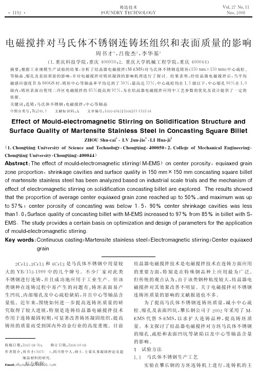
$ ! # ! " # $ % & ’ $ ( + )) : : ) * 9" :< " # , % I ) , ) * 9 & " < 4 $ ) 9 7 *8 9 7 & & 7 $ X I U X W" " $* ) $ 9 ) &; " & " 8 7 9 ) # 7 4 F ) %& 4 7 $ ’ E # 8 + & 7 $ 5 4 )* 4 ? 7 9 7 ) 84 $ %8 # & : 4 * )E # 4 , 7 9 7 $2 K >< <J2 K >< <* " $ * 4 8 9 7 $ # 4 & )3 7 , , ) 9 G " $ ); & " " & 9 7 " $ ’ -8 E ; " :< 4 & 9 ) $ 8 7 9 )8 9 4 7 $ , ) 8 8 8 9 ) ) , + 4 83 ) ) $4 $ 4 , G ) %3 4 8 ) %" $ 7 $ % # 8 9 & 7 4 , 8 * 4 , ) 9 & 7 4 , 84 $ % 9 + )< ) * + 4 $ 7 8 <" : ’ ) : : ) * 9 " : ) , ) * 9 & " < 4 $ ) 9 7 *8 9 7 & & 7 $ $8 " , 7 % 7 : 7 * 4 9 7 " $* " $ * 4 8 9 7 $ 7 , , ) 9 4 & )) F , " & ) % C ( + )& ) 8 # , 9 88 + " 6 ) % -" -3 ; 9 + 4 9 9 + ); & " " & 9 7 " $" : 4 ? ) & 4 )* ) $ 9 ) &) # 7 4 F ) %& 4 7 $G " $ )& ) 4 * + ) %# 9 "K >b # 4 $ %< 4 F 7 < # <6 4 8# ; E ; ; * ) $ 9 ) &; " & " 8 7 9 :* " $ * 4 8 9 7 $ 4 83 ) , " 6 2C K# @ >b * ) $ 9 ) &8 + & 7 $ 5 4 )* 4 ? 7 9 7 ) 86 4 8, ) 8 8 9 "K Mb % ’" -6 9 + 4 $ 2C >% W # & : 4 * )E # 4 , 7 9 : * " $ * 4 8 9 7 $ 7 , , ) 96 7 9 +X I U X W 7 $ * & ) 4 8 ) % 9 "@ Mb: & " <L Kb7 $3 7 , , ) 96 7 9 +W I ’" -3 U X WC ( + )8 9 # % & " ? 7 % ) 84* ) & 9 4 7 $3 4 8 7 8" $" 9 7 < 7 G 4 9 7 " $4 $ %% ) 8 7 $" : 4 & 4 < ) 9 ) & 8 : " & 9 + )4 , 7 * 4 9 7 " $ ’; ; ; ; ; " :< " # , % I ) , ) * 9 & " < 4 $ ) 9 7 *8 9 7 & & 7 $ C $ % % % ( ) , % # Q " $ 9 7 $ # " # 8* 4 8 9 7 $ X 4 & 9 ) $ 8 7 9 )8 9 4 7 $ , ) 8 88 9 ) ) , U , ) * 9 & " < 4 $ ) 9 7 *8 9 7 & & 7 $ Q ) $ 9 ) & ) # 7 4 F ) % *+ E & 4 7 $ < L & ?& ? < L & ?和’ < L & ? 是马氏体不 锈 钢 中用 量 较 !!! 大的 9 ’ ^ & E ? $ & % % % 中 的 几 个 牌 号( 不 少 厂 家 对 此 类 不锈钢进行连铸 # 并 且 成 功 地 应 用 于 工 业 生 产( 但 该 类钢种在连铸过程中 易 产 生 的 问 题 有 $ 铸坯表面易产 生凹坑 & 内部缩孔及中心疏松缺陷 # 并且中心等轴晶含 量低 ( 近年来 # 围绕如 何 进 一 步 提 高 连 铸 坯 质 量 的 研 究取得了较大进展 # 特别是连铸结晶器电磁搅拌技术 作用于连铸凝固初期 # 可显著改善铸坯凝固组织 # 提高 铸坯的质量而受到国内外冶金行业的高度重视 ( 目前 结晶器电磁搅拌技术是电磁搅拌技术在连铸方面应用 的重要方 面 # 特 别 是 在 特 殊 钢 品 种 上 应 用 最 为 广 泛( 但传统的观点认为 $ 由于该类钢种粘度较大 # 结晶器电 磁搅拌对其效果改善不明显 ( 关于电磁搅拌对不锈钢 连铸坯质量的影响的文献报道也不多 ( 为了提高马氏体 不 锈 钢 连 铸 坯 质 量 # 减小中心疏 松& 缩孔及表面凹坑 # 攀长钢公司于 ! " " ! 年采用了 X $ 代 替 # 以 求 扩 大 连 铸 品 种 # 提 高 铸 坯 质 ;XJ J $ ;XJ 量 ( 本文探讨了结晶器电磁搅拌对方坯马氏体不锈钢 的缩孔 & 疏松和表面 凹 坑 等 缺 陷 以 及 中 心 等 轴 晶 含 量
电磁搅拌技术在连铸优钢生产中的应用及分析

电磁搅拌技术在连铸优钢生产中的应用及分析摘要:为了提高特钢生产的品质,文章主要针对八钢70t电炉连铸,以及连铸电磁搅拌系统。
从技术特点、针对性的选型、功能介绍及效果对比等方面进行了全面的分析。
关键词:电磁搅拌;漏磁;钢液粘度1前言2006年初,八钢第二炼钢厂70t电炉根据公司下达的生产任务,通过内部挖潜针对优钢生产进行了新一轮的实验,取得了良好的效益,优钢生产产品质量较以前有了较大的进步。
但目前铸坯内部质量仍然存在一些问题。
2电磁搅拌器技术特点连铸电磁搅拌器具有以下特点:①采用低电压、大电流的设计方案,有效地防止高压峰值对绝缘的破坏。
②对L/D比值进行优化,适当加长搅拌器的长度。
③适当放宽电源频率范围。
④适当降低搅拌器安装位置,使弯月面附近的磁场尽可能小。
⑤采用纯净水直冷式电磁搅拌器,漏磁少,中心磁感应强度高,搅拌效果好。
3电磁搅拌结构的分类及性能比较从电磁搅拌器所处安装于连铸机位置分:结晶器电磁搅拌器;二冷区电磁搅拌器;凝固末端电磁搅拌器。
从电磁搅拌器所使用的冷却方式分:油―水冷却电磁搅拌器;水直接浸泡冷却式电磁搅拌器;空芯铜管纯水内冷式电磁搅拌器。
从电磁搅拌器所产生磁场形态分:旋转磁场电磁搅拌器;行波磁场电磁搅拌器;螺旋磁场电磁搅拌器。
现在方坯电磁搅拌普遍使用了结晶器电磁搅拌器,结晶器电磁搅拌器从结构上来讲又分为两类:结晶器内置式电磁搅拌器;结晶器外置式电磁搅拌器。
针对以上电磁搅拌各种不同方式,综合70t电炉连铸的现状,采用的是M-EMS,从结晶器电磁搅拌器的结构上采用了结晶器内置式电磁搅拌器。
4电磁搅拌的原理及分析连铸电磁搅拌的实质在于借助电磁力的作用来强化铸坯中末凝固钢液的运动,从而改变钢水凝固过程中的流动。
影响连铸电磁搅拌的冶金效果的主要因素在于①电磁搅拌器能否提供足够大的电磁推力。
②不同钢种的末凝固钢液需要多大的电磁推力。
③电磁搅拌的作用区域是否足够大。
④电磁搅拌的安装位置是否得当。
- 1、下载文档前请自行甄别文档内容的完整性,平台不提供额外的编辑、内容补充、找答案等附加服务。
- 2、"仅部分预览"的文档,不可在线预览部分如存在完整性等问题,可反馈申请退款(可完整预览的文档不适用该条件!)。
- 3、如文档侵犯您的权益,请联系客服反馈,我们会尽快为您处理(人工客服工作时间:9:00-18:30)。
SURFACE QUALITY IMPROVEMENT OF CONTINUOUSLY CAST SLAB WITHIN-MOLD ELECTROMAGNETIC STIRRINGJunji Nakashima - Steelmaking R&D Div., Nippon Steel Corporation, Chiba, JapanJ.Fukuda, T.Kawase, Y.Ohtani, M.Doki - Kimitsu Works,Nippon Steel Corporation, Chiba, JapanA.Kiyose - Kimitsu R&D Lab., Nippon Steel Corporation, Chiba, Japan ABSTRACTTo meet users’ quality demands and needs for production cost savings to realize high quality slabs, the transition part of slab surface defects was improved by electromagnetic stirring (EMS). In this study, analysis of the influence of molten steel flow on homogenization of initial solidification continuously cast slabs was conducted. By applying EMS to produce middle carbon steel, it was confirmed that EMS remarkably improves the uniformity of solidification shell thickness over the slab width. We discussed the influence of molten steel flow on temperature in the mold, heat flux to the mold plate, and the frequency of nucleus formation. In the large-scale application to commercial production, EMS contributes to the reduction of surface defects originating from longitudinal cracks.KEYWORDSlongitudinal crack; continuous casting; initial solidification; solidification; medium carbon steel; electromagnetic stirring; EMSINTRODUCTIONMost heavy plates and tubes are made of middle carbon steel, and the slab surface tends to cause longitudinal cracks due to unevenness of the initial solidifying shell thickness. Recently, use of increasing amounts of high-alloy steel has increased the production of crack sensitive steel grades. When cracks are detected in a slab, that slab is sent to downstream processes after slab dressing. But more severely defective slabs become waste. If the slab is rolled with undetected cracks, microscopic cracks in the slab may then result, and these may also be detected as product defects after rolling. Thus, for the production of heavy plates and tubes, suppressing cracks in the slab improves not only yield but also lead times and heat loss due to direct rolling. The effect of directly rolling slabs is significant from the perspective of reducing the environmental impact. The effect of molten steel flow provided by EMS on the reduction of longitudinal cracks has been reported [1-4]. However, the mechanisms for reducing longitudinal cracks due to induced molten steel flow are unclear. Particularly, the mechanism of initial solidification conditions and initial solidification uniformity in the continuous casting slabs has not been clarified. In this study, by applying in-mold EMS, the effect on temperature field and actual situation of the initial solidified shell were investigated and the influence of molten steel flow on the homogenization of initial solidification discussed. EXPERIMENTAL PROCEDURESTests were conducted on a Kimitsu No2 continuous casting machine to clarify the improvement effects of EMS on the initial solidification. MEASUREMENT OF MOLTEN STEELTEMPERATURE & HEAT FLUX IN MOLD To investigate the change of molten steel temperature in the mold caused by the application of EMS, the molten steel temperature was measured at 9 grid points as shown in Fig.1 [3].Fig. 1 Schematic drawing of temperature Measuring position in mold.The measurement was performed using three thermocouples, immersing them together into the molten steel, and alternately switching EMS from on to off and vice versa.Table1 show the casting conditions for temperature measurement.Table 1. Casting conditions fortemperature measurement.To clarify the change of heat flux in the mold as a result of EMS, temperature differences between the inlet and outlet of mold cooling water were measured. Table 2 shows the casting conditions for heat flux measurement.Table 2. Casting conditions for heat fluxmeasurement.MEASUREMENT OF INITIAL SOLIDIFICATION SHELL THICKNESSThe change of the shape of the initial solidification shell was evaluated by a sulphur addition test. A prescribed amount of sulphur reagent was added to the molten steel in the mold. The shape of the initial solidification shell was evaluated by the sulphur print method at the cross section of cast slabs as shown in Fig.2.Fig. 2 Schematic drawing of sampling position for sulphur addition test. The solidification shell thickness in the slab width direction was measured at 5mm intervals [5]. Table 3 shows casting conditions for the sulphur addition tests.Table 3. Casting conditions for sulphur addition test.EXPERIMENTAL RESULTS &DISCUSSIONMEASUREMENT RESULTS OF MOLTENSTEEL TEMPERATURE IN MOLDFigure 3 shows the temperature change at the 9measuring points in the mold. Using EMS confirmedthat the molten steel temperature was changed by 1to 2℃ or so at each point and while the temperaturechange was not the same at all the measuring points,the steel temperature was homogenized in the moldsection as a whole [3]. With EMS, the standarddeviation of temperature change at the 9 measuringpoints decreased from 1.75℃ to 0.83℃.Fig.3 Distribution of molten steeltemperature in the Mold.Measuring surfaceFigure 4 shows the effect of EMS on heat flux homogenization in the mold. In the case of without EMS, there are large differences between the heat flux of the loose face side and the heat flux of the fixed face side. But in the case of with EMS, those differences diminish to become almost equal.Fig.4 Effect of EMS on mold heat fluxBy applying EMS, a stable circulating molten steel flow in the mold is formed. So the heat transfer differences between the loose face side and fixed face side in the mold decrease. As a result, the uniform molten metal flow in the mold creates a homogeneous heat supply to solidification front in the mold.MEASUREMENT RESULT OF INITIAL SOLIDIFICATION SHELL THICKNESSFigure 5 shows the solidification shell thickness in the slab width direction measured by the sulphur print method. As is clear from the figure, local delays in solidification were reduced, the fluctuation of shell thickness decreased and thus, uniform shell thickness was realized by the application of EMS. Figure 6 shows the effect of EMS on the standard deviation of solidification shell thickness at the same slab location. By applying EMS, as is clear from the figure, the fluctuation shell thickness is suppressed across the slab width and throughout the casting time. When in-mold EMS is applied, homogeneous circulating flow in the mold is created, andunevenness of the initial solidification shell reduced. EMS improves the uniformity of solidification shell thickness over the slab width.Fig. 5 Distribution of shell thicknessmeasured by sulphur print.Fig. 6 comparison of standard deviation ofshell thickness.To discuss the effectiveness of the speed of molten steel on the solidified shell unevenness, an investigation using a small molten steel model was conducted [6]. In this experiment, a rotated cylinder (30mm in diameter) was dipped into molten steel in a 300kg induction furnace for 5 seconds. After cooling down, the unevenness (i.e. deviation of shell thickness) was quantified and related to the rotation speed. The shell thickness showed reduced unevenness, with the increase in the cylinder surface0.00.51.01.52.00.00.51.01.52.0Standard deviation ofshell thickness(EMS OFF) /mmS t a n d a r d d e v i a t i o n o f s h e l l t h i c k n e s s (E M S O N ) /m mvelocity. Especially in the case of middle carbon steel, the thermal boundary layer thickness between the solidification front and the molten steel is reduced with the increase in molten metal velocity. The heat transfer is controlled by the input heat flux from the molten steel and then the shell will grow uniformly. Figure 5 shows difference of the shell thickness with and without EMS. There is a slight difference in minimum shell thickness (0.9mm) between with and without EMS. In contrast there is significant difference in maximum shell thickness (5.3mm) between with and without EMS. These data show the same tendency as the dip experiment.In addition to the previous discussion a numerical simulation was proposed as follows [6]. In this case the maximum velocity level is set at 40cm/s in the unidirectional flow field in the duct whose velocity is ordinarily applied by in-mold electromagnetic stirring in actual application. In the case of the duct flow driven by pressure inclination, the thickness of the boundary layer becomes 3mm, and in the case of the flow driven by the electromagnetic force, it becomes 1mm. On the velocity inclination near the boundary, it becomes three times larger in the latter case than the former [6]. By applying EMS, the flow in the vicinity of the solidifying shell front is not a detached flow but a steady swirl flow. Therefore, the electromagnetically driven flow with EMS stabilizes the heat transfer from the molten steel to the initial solidifying shell.THE EFFECT OF THERMAL CONDITION ON INITIAL SOLIDIFYING SHELL GROWTHThe effect of in-mold EMS on initial solidifying shell growth has been verified by measuring the molten steel temperature and initial solidifying shell thickness. Table 4 shows the concept of initial solidification improvement with EMS. By applying EMS, the unsteady molten steel flow caused by discharge flow of the submerged entry nozzle becomes a stable circulating flow induced by electromagnetic force. Accordingly a ununiform temperature of molten steel in the mold decreases the variations in the mold steel. As a result, the melting rate of the mold flux is stable. As variations in mold heat flux are reduced as a result of even inflow of mold slag, it is considered to be stabilized for that initial solidification. As a result, it is possible to consider reducing the longitudinal cracks in the middle carbon steel, even when there is a thermal unsteady cast in part of the slabs.The difference in consumption of mold flux applied with and without in-mold EMS was observed. Table 4. Concept of initial solidificationimprovement with EMS.CONCLUSIONIn this study, to reduce the longitudinal cracks in the medium carbon steel for heavy plates and tubes, the effects of molten steel flow on the unevenness of initial solidified shell thickness with EMS were noted as follows.(1) By applying in-mold EMS, molten steel temperature variation is small as a steady swirl flow is formed in the mold. As a result, the heat flux from molten steel to the mold plate becomes stable. (2) By applying in-mold EMS, the maximum initial solidified shell thickness is decreased, and the fluctuation of shell thickness is decreased over the slab width. These results show similar laboratory-scale test results.As mentioned above, by applying in-mold EMS with a continuous casting machine, the electromagnetic driven flow is applied to the solidifying shell front, leading to thermal stability of the molten steel in the mold. As a result, the uniformity of initial solidifying shell thickness in the mold is improved, longitudinal cracks of medium carbon steel slabs are reduced, and the surface quality of continuously cast slabs is improved.The effect of molten steel flow applied by EMS, in the case of slab surface cleanliness was the molten steel flow itself, but, in the case of stabilizing initial solidification, the thermal uniformity of the molten steel in the mold was found to mediate the effects. Flow in moldPowder infiltrationSolidificationREFERENCES1)H.Yuyama, M.Suzuki, H.Misumi, H.Yamamura and Y. Ide: CAMP-ISIJ, 1(1988),1220.2)Y.Ohtani, J.Fukuda, N.Iwata, N.Ishiwata and K.Funato: CAMP-ISIJ,7(1994),1194.3)Y.Ohtani, T.Kawase, J.Fukuda, J.Nakashima, K.Nakamura, T.Yamazaki: CAMP-ISIJ,8(1995),348.4)T.Miyake, M.Morishita and M.Kokita: CAMP-ISIJ, 15(2002),903.5)J.Nakashima, J.Fukuda, A.Kiyose, T.Kawase, Y.Ohtani, M.Doki and K.Fujisaki: Testu-to-Hagane,93(2007),2116)H.Yamamura, Y.Mizukami and Y.Ueshima: CAMP-ISIJ, 9(1996),592.7)T.Toh, H.Hasegawa and H.Harada: ISIJ Int., 41(2001), 1245.。