FM-180指纹识别模块用户手册
指纹识别命令 详解
(1)打开“003 指纹识别模块用户手册.pdf”先看第2页,参数介绍。
模块工作在3.6V-6V,他的波特率出厂设定在9600 bps。
RXD、TXD兼容CMOS和TTL电平,也就是3.3V和5V都兼容。
(2)接着第3页模块接线介绍。
(3)再仔细查看第4、5页的内容。
“命令包格式”这个是主机(上位机)发送给模块的,“数据包格式”和“结束包格式”(这两个命令可以是上位机发,也可以是模块发),要注意的包的格式。
“指令应答”(指纹模块应答包格式)。
需要注意的是校验位的计算方法:“校验和是从包标识至校验和之间所有字节之和,超出2 字节的进位忽略。
”第6、7、8、9页也需要查看一下。
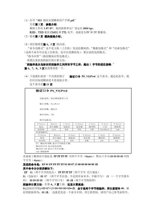
(4)下面我们来讲一个具体的例子---- 验证口令PS_VfyPwd这个命令,通过此命令,我们可以知道模块是不是连接正常。
这个命令在第21页从前面了解到芯片地址是FF FF FF FF 共四个字节(4bytes),默认口令为00 00 00 00共四个字节(4bytes)。
发送的命令是:EF 01 FF FF FF FF 01 00 07 13 00 00 00 00 00 1B其中命令分分别讲解如下:EF 01(两个字节的包头)FF FF FF FF(四个字节芯片地址)01(包标识)00 07 (两个字节长度,不足的用0补齐,不能不写)13 (一个字节指令码)00 00 00 00 (四个字节口令)00 1B(两个字节校验和)校验和计算方法:在第4、5页上面,这里计算就是:01(包标识开始)+00+07+13+00+00+00+00=1B,由于是两个字节校验和,所以前面补00,最好的校验和为:00 1B。
这就是发送一个命令介绍,其它的类似,请用户自己参考说明书。
请注意,用户最好不要随意更改地址和口令,除非需要,否则不要更改,以免您记不住,或者更改错误,就需要返厂维修了(重新下载程序)。
Smartgen HGM180 180HC 自动启动模块操作手册说明书
HGM180/180HCAUTO START MODULE OPERATING MANUALSMARTGEN ELECTRONICSHistoryVersion Date Content1.0 2007-1-18 Original release.© Smartgen ElectronicsAll rights reserved. No part of this publication may be reproduced in any material form (including photocopying or storing in any medium by electronic means or other) without the written permission of the copyright holder except in accordance with the provisions of the Copyright, and Designs.Applications for the copyright holder’s written permission to reproduce any part of this publication should be addressed to Smartgen Electronics.Any reference to trademarked product names used within this publication is owned by their respective companies.Smartgen Electronics reserves the right to change the contents of this document without prior notice.CONTENT1. DESCRIPTION (4)2. SPECIFICATION (4)3. OPERATION (5)4. OVER SPEED PROTECTION (6)5. CHARGE FAILURE WARNING (6)6. CONFIGURATION (6)7. TERMINAL DESCRIPTION (7)8. CASE DIMENSIONS (8)9. TYPICAL CONNECTIONS (8)1. DESCRIPTIONThe HGM180 auto start module is an engine control module designed to control the engine via a key switch and remote start signal or pushbuttons on the front panel. The module is used to start and stop the engine and indicate fault conditions, automatically shutting down the engine and indicating the engine failure by LED, giving true, first-up fault annunciation.The module is housed in an enclosed robust plastic case for front panel mounting. Connections to the module are via plug and sockets.The HGM180hc has an inbuilt LCD hours counter, which displays the number of hours that the generator has run, to the nearest 1/10 hour.2. SPECIFICATIONDC Supply8 to 35V continuous.Alternator Input Range15 - 300VAC(+20%) RMSAlternator Input Frequency50 - 60 Hz at rated engine speed.Over speed: nominal frequency +14% (+24% Overshoot)Start OutputRelay 1A plant battery positive B+ terminalFuel OutputRelay 1A plant battery positive B+ terminalPre-heat OutputRelay 1A plant battery positive B+ terminalStop OutputRelay 1A plant battery positive B+ terminalConfigurable OutputRelay 1A plant battery positive B+ terminal. Thisoutput can configure Alarm output or Idle output by thecode switch on the under side. When idle output iseffectual, it is active at full speed.Four switch InputsSwitch to negative.Fixed SettingsCrank Disconnect: Generator voltage ≥15VAC frequency ≥15HzCharge Failure Voltage: ≤3VRemote start delay: 2secondsCrank period: 5secondsCrank rest: 10secondsSafety delay: 10secondsRemote stop delay: 10secondsHours counterMaximum hour counts: 99999.9hCase Dimensions84mm x 72mm x 35mmOperating Temperature Range-30 to +70°CICON AND LED: High temperature alarm LED: Low oil pressure alarm LED: Over speed alarm LED: Charge Failure warn LED: Common alarm LED: LCD hour count3. OPERATIONIf you use hgm180/180hc for the first time, configure is necessary. If you want to configure the module, please look Configuration.Operation of the module is via a three position key switch mounted on the front panel with OFF(O), START()and AUTO() positions. In the ‘O’ position the output are de-energized.Manual Operation:1. Select manual run()2. Depress pre-heat button for required length of time3. Press START()to crank engineOnce the Start button is pressed and maintained, the engine fuel system is energized. After 1s, the ‘Crank’ output is then energized and the starter motor operated, disengaging automatically when the engine fires or when the ‘Start’ button is released. The protection hold-off timer is then initiated.Automatic Operation:1. Select AUTO()2. When Remote Start is active, the generator will automatic start.Stop Operation:Turn the key to OFF (O), the engine will stop. The stop relay will energize for 30 second (maximum) or 10s (when the engine has stopped).Operation of any of the following alarms (which are close on fault) will cause the run output to de-energize:. Low Oil Pressure. High Engine Temperature. Auxiliary Shutdown. Over speedThis will remove the fuel supply from the engine and bring it to rest. Each alarm has its own LED indicator and once activated no further alarm conditions will be accepted. The alarm output and relevant LED will remain active until the unit is reset by turning the switch to the ‘O’ position.4. Over speed ProtectionOver speed protection is derived from the generator Hz output. The over frequency circuit monitors the generator Hz output and will shut down the engine immediately if a pre-set frequency level is exceeded. This trip level is 114% of nominal frequency.5. Charge Failure warningCharge Failure warning is also provided by monitoring the WL terminal on the charge alternator. This operates on a similar principal to the warning lamp fitted in a motor vehicle, should the output fail the charge fail LED will illuminate. The module will also provide the alternator excitation current via this connection.6. Configuration6.1 Turn the position key to the ‘O’ position, press the set button()over 5 second, configuration mode will is selected. The Pre-Heat button()can be usedto select the following item ,The set button()will allow the user to change the value of the function.30 Seconds 60 Seconds 120 Seconds 50Hz(Default ) Alternator Frequency60Hz5 Seconds10 Seconds(Default) 15 Seconds 20 Seconds 30 Seconds 60 Seconds 120 Seconds Idle time180 SecondsDisable Oil pressure disengage startermotorEnable (Default)Note:indicate LED to illumine, indicate LED to extinguish. 6.2 Turn the position key to the ‘’ position or the ‘’ position, quit configurationmode.7. TERMINAL DESCRIPTIONPIN NO DESCRIPTION CABLE SIZE NOTES1 DC Plant supply input (B-)1.0mm Connected to plant battery negative 2 DC Plant supply input (B+)1.0mm Connected to plant battery positive (Recommended Fuse 6A)3 Fuel relay output 0.5mm Used to operate the fuel solenoid control relay.4 Start relay output 0.5mm Used to operate the cranking control relay.5 Preheat output0.5mm Used to operate the preheat control relay.6Auxiliary shutdown input 0.5mm Switch to negative on fault.7Charge fail input/ excitation output1.0mmMust NOT be connected to plant supply negative if not used.8Low oil pressure switch input0.5mm Switch to negative on fault. 9High engine temperature switch Input0.5mm Switch to negative on fault. 10 Alternator input L 1.0mm 2A Fuse 11 Alternator input N1.0mmPIN NO DESCRIPTIONCABLESIZENOTES12 Configurable output 0.5mm Used to operate the auxiliary control relay.13 Stop output 0.5mm Used to operate the stop control relay.14 Remote start input 0.5mm Switch to negative to start set.8. CASE DIMENSIONS9. TYPICAL CONNECTIONS。
指纹识别访问控制系统用户手册说明书
5.WiringColor Marks DescriptionGreen White Grey Yellow Brown Red Black Blue Purple Orange D0D1ALARMOPEN/ BEEPD_IN/ LED+12VGNDNOCOMNCWiegand input (Wiegand output as reader mode)Wiegand input (Wiegand output as reader mode)Alarm signal MOS tube drain output end (optional)Exit button input end (Beeper input as reader mode)Door contact switch input end (LED input as reader mode) (optional)Positive power supplyNegative power supplyRelay NO endRelay COM endRelay NC end6.Diagram6.1 Common Power Supply6.2 Special Power SupplyNote: The door contact and alarm function are optional Note: The door contact and alarm function are optional6.3 Reader Mode7.Sound and Light IndicationLight indicatorOperation StatusBuzzerBeep—Beep-Beep-Beep Beep—Beep Beep—Beep-Beep AlarmRed GreenRed indicator flash slowly Red indicator flash slowly Red indicator flash slowly Orange GreenRed indicator flash quicklyStand byOperation successful Operation failedOn process of reading multi user card Enter programming mode Enter setting status Unlocking Buzzer alarmRead card under fingerprint + code mode Press * keyPress digital key Admin card exit programming Admin card enter programming 8.Admin Menu8.1 Standalone Mode SettingsDevice ManagementEnterprogramming MenuOperation steps DescriptionDefault valuePress *Admin code #(Defaultadmin code is "999999")New admin code # new admincode #Change admin code Delete admin add card or admin add fingerprintSet admin add card or admin add fingerprintSet admin delete card or admin delete fingerprintDelete admin delete card or admin delete fingerprintStandalone access control mode ( 26-58 ) #8 #13 #12 #11 #10001# *10001# Read card / Input afingerprint twice *10002# Read card / Input a fingerprint twice *10002# *01238Wiegand 26-58 bits output Reader modeRelay toggle mode WIFI matchingOptional11999999Add and Delete UsersAccess WaysAdvanced SettingsEnterprogramming EnterprogrammingMenuMenuOperation stepsOperation stepsDelete usersDescriptionDescriptionDefault valueDefault valueEnterprogrammingMenuOperation stepsDescriptionDefault valuePress *Admin code #(Defaultadmin code is "999999")Press *Admin code #(Defaultadmin code is "999999")Press *Admin code #(Defaultadmin code is "999999")“…” means repeating the previousoperation,Press * key to exit.“…” means repeating the previous operation,Press * key to exit.Read card / Input a fingerprint twice... *Add card users or fingerprint users continuouslyAdd card users by card number Add card users or fingerprint users by specific ID numberAdd card users by specific ID number and card number Delete card users by readingcard / Delete fingerprint users by inputting fingerprintPress 8 or 10 digits card number # … *Read card / Input a fingerprint once … *(0-300) #Door opening time range: 0-300S 0 equals to 50mSMatch fingerprints to a card (Maximum 2 fingerprints)The external alarm and built-in buzzer will work if wrong operations are over 5 times.The device will be locked out for 10 min if wrong operations are over 5 times.Add conductive number cardNormal working modeDisable light indicator Enable light indicator Disable buzzer Enable buzzerAlarming time range: 0-99 min.(0-99) #0#1#2#3#4#5#6#6450Read user card, input the first fingerprint twice, input the second fingerprint twice...*Press ID number # press 8or 10 digits card number #input card quantity #Press 8 or 10 digits card number #… *Delete card users by card number Delete users by ID number Delete ALL usersEntry by card or fingerprint Entry by card + fingerprintEntry by multi-card / multi-fingerprintPress ID number # (0000)Press ID number # Read card / Input a fingerprint twice … *Press ID number # Press 8 or 10 digits card number # … *1300 #1 #2-10 #2456789.Admin Operation9.1 Add Users10. Other Operation10.1 Remove Alarm8.2 Reader Mode Settings 9.2 Delete Users10.2 Reset to Factory DefaultNote :When the alarm is activated, users can remove the alarm by reading a valid card orinputting valid fingerprint or pressing valid admin code.Note : Registered user data won’t be deleted when reset to factory default.Users can reset to the factory default when the admin code is forgotten, or the default settings have been modified disorderedly, operations as below:Power off, press and hold the exit button continuously, power on, release the exit button until hearing beep sound twice, the admin code has been reset to 999999, factory default settings are successful.Note :The admin delete card / admin delete fingerprint is used to delete card / fingerprint userscontinuously and quickly. When you read the admin delete card / admin delete fingerprint at the first time, you will hear short "BEEP" sounds twice and the indicator light turns orange, it means you have entered into delete user programming, when you read the admin delete card / admin delete fingerprint at the second time, you will hear long "BEEP" sound once, the indicator light turns red, it means you have exited the delete user programming.EnterprogrammingMenuOperation steps DescriptionDefault valuePress *Admin code #(Defaultadmin code is "999999")“…” means repeating the previous operation,Press * key to exit.New admin code # Repeatnew admin code #Change admin code Set admin add card or admin add fingerprint Set admin delete card or admin delete fingerprint Delete admin add card or admin add fingerprint Delete admin delete card or admin delete fingerprint Add fingerprint users continuouslyAdd fingerprint users byspecific ID number 10001# Read card / Inputa fingerprint twice *10001# *Input a fingerprint twice... *Input a fingerprint once... *Delete fingerprint users Delete ALL users Wiegand 26-58 bits output Device numberAlarming time range: 0-99 min 10002# *0000 # (26-58) #(0-99) #(0-255) #02699999910002# Read card/ Input a fingerprint twice *Press ID number # Input a fingerprint twice … *01212359Read valid card Input valid fingerprint Press admin code#Note : The admin add card / admin add fingerprint is used to add card / fingerprint userscontinuously and quickly. When you read the admin add card / input the admin add fingerprintat the first time, you will hear short "BEEP" sounds twice and the indicator light turns orange, it means you have entered into add user programming, when you read the admin add card / input the admin add fingerprint at the second time, you will hear long "BEEP" sound once and the indicator light turns red, it means you have exited the add user programming.Read admin add card / Input admin add fingerprint Read admin add card / Input admin add fingerprintRead the 2 user card / Input the 2 fingerprint twice Read the 1 user card / Input the 1 fingerprint twice …,,Read admin delete card / Input admin delete fingerprint Read admin delete cardRead the 2 user card / input the 2 fingerprint once Read the 1 user card / Input the 1…,,or or fingerprint twice。
移动警务终端用户手册(新版)

移动警务终端用户手册移动警务终端用户手册前言忠心感谢您使用本公司产品,我们将竭诚为您提供最优质的服务。
本手册内容仅供参考,本手册内容将根据产品功能的增强而更新,如有更新恕不另行通知,更新内容将会在本手册的更新版本中加入。
本手册可能包含技术上不准确的地方或产品功能及操作不相符的地方或印刷错误,真诚希望您把意见及时反馈给我们,在以后的版本中,我们会加以充实和改进。
移动警务终端用户手册目录1. 产品概述 (1)2。
安全须知 (1)2。
1一般安全 (1)2.2电池安全 (1)2。
3充电器安全 (2)3。
设备说明 (3)4. 操作指引 (4)4.1开机 (4)4。
2电池 (4)4.3充电 (5)4.4使用数据线 (6)4.5数据同步操作 (6)5. 操作说明 (11)5。
1查人 (13)5.1。
1 二代证查询 (13)5。
1.2 手动录入查询 (15)5.2查车 (17)5.3万能查询 (19)5。
4记录查询 (20)5.5拍照 (21)5。
6照片浏览 (22)5。
7卡授权 (22)5.8指纹授权 (24)5.9系统信息 (26)5.10系统维护 (27)移动警务终端用户手册5.11时间设置 (28)5。
12切换用户 (29)5。
13关机操作 (30)附录A 常见问题解答 (31)附录B 装箱单 (33)移动警务终端用户手册1。
产品概述移动警务终端让民警利用此智能设备作为民警的标准装备,完成路面盘查,人员、物品、运动轨迹的动态采集,革命性地让民警从“被”使用电脑的困境中解放出来,轻装上阵,解放警力.该设备有二代证安全模块,13.56射频全能型读头,13.56射频卡写入模块,警用指纹采集模块,指纹比对模块,300万像素摄像头,USB接口,数字及功能键盘,3。
2寸彩屏,工业三防外观设计。
能够自动读取二代证信息和指纹信息以及SIM卡,读取和写入13。
56M的IC卡芯片信息,脱机比对在逃及敏感人群,拍摄车牌号,并脱机比对涉案车辆,还能采集指纹和比对指纹,采集人员照片,联机公安网同步数据,进行密集信息查询,同现有的公安社区管理系统和警综系统无缝结合.2. 安全须知2。
FM180-N中文资料
12 FM
0-
100
01 FM N~ 40 -N
0 11 FM N~ 0N
120
140
160
180
200
18 FM
0-
N~
00 11 FM
-N
Tj=25 C Pulse Width 300us 1% Duty Cycle
0.1
PEAK FORWARD SURGE CURRENT,(A)
24
.01
IR
C
SYMBOLS
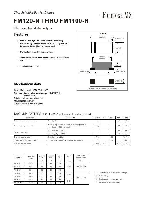
MARKING CODE SS12 SS13 SS14 SS15 SS16 SS18 S110
V RRM
*1
V RMS
*2
VR
*3
VF
*4
Operating temperature (o C)
(V) FM120-N FM130-N FM140-N FM150-N FM160-N FM180-N FM1100-N 20 30 40 50 60 80 100
.1
.3
.5
.7
.9
1.1
1.3
1.5
18
Tj=25 C 8.3ms Single Half Sine Wave JEDEC method
FORWARD VOLT AGE,(V)
12
6
FIG.5 - TYPICAL REVERSE
0 1 5 10 50 100
CHARACTERISTICS 100
NUMBER OF CYCLES AT 60Hz
元器件交易网
RATING AND CHARACTERISTIC CURVES (FM120-N THRU FM1100-N)
指纹传感器FM-180资料

我们的目标是:帮助您开发出自己的指纹产品!您的成功是我们前进的动力!送的电路图与程序可以实现以下功能,您可以先观看视频。
看一看是否符合您的要求。
谢谢光临……/v_show/id_XMjY4OTI5MDUy.htm l(复制到IE地址栏里面)本模块非常方便您进行二次开发.(店主也可以帮忙提供二次开发,但是另外付费哦。
(谢谢))2.54MM接口,出货时候已经接上了四根2.54MM接口的杜邦线。
使用非常方便。
如下图所示:图(一)2.54MM杜邦线接头图(二)模块非常小巧,使用方便。
如图(二)所示。
接线说明:1.红色线:VCC2.绿色线:TXD3.白色线:RXD4.黑色线:GND出厂波特率:9600(用户可以自行更改波特率,详见说明书)用法非常简单:只要有串口的嵌入式都能操作这个模块,MSP430、51、AVR、PIC、ARM、FPGA等芯片都操作这个模块。
这个模块通过串口控制。
您也可以用电脑的串口来控制这个模块。
KX-V6(凯旋-Version 6.0版本)系列指纹识别模块我司推出的新一代光学指纹模块产品,拥有自主开发与创新产权。
该系列产品突破性地解决了目前行业内光学指纹识别模块存在的干手指适应性、产品一致性、产品体积与厚度三大难题:采集头表面经过特殊处理,有效解决光学传感器采集干手指适应性较差的问题,在采集头元器件选择上率先采用特殊材料,彻底解决了传统玻璃三棱镜产品一致性较低的问题,在光路设计和比对算法开发上取得重大突破,解决了光学识别模块厚度较大,指纹类产品开发外观设计受限的问题。
产品由:光学指纹传感器、高速DSP处理器、高性能指纹比对算法、超大容量的FLASH芯片等软硬件构成。
本指纹模块系列产品:性能稳定、功能完善、兼具指纹采集、指纹登记、指纹比对、指纹搜索等多种功能。
特别适合于各种门禁、考勤、保险箱(柜)、门锁等产品的开发、性价比超高!指纹容量:162枚产品特点:(1)功能完善:独立完成指纹采集、指纹登记、指纹比对(1:1)和指纹搜索(1:N)功能。
指纹读卡器用户手册说明书

指纹读卡器用户手册版权所有©杭州海康威视数字技术股份有限公司2019。
保留一切权利。
本手册的任何部分,包括文字、图片、图形等均归属于杭州海康威视数字技术股份有限公司或其子公司(以下简称“本公司”或“海康威视”)。
未经书面许可,任何单位和个人不得以任何方式摘录、复制、翻译、修改本手册的全部或部分。
除非另有约定,本公司不对本手册提供任何明示或默示的声明或保证。
关于本手册本手册描述的产品仅供中国大陆地区销售和使用。
本手册作为指导使用。
手册中所提供照片、图形、图表和插图等,仅用于解释和说明目的,与具体产品可能存在差异,请以实物为准。
因产品版本升级或其他需要,本公司可能对本手册进行更新,如您需要最新版手册,请您联系我们。
海康威视建议您在专业人员的指导下使用本手册。
商标声明为海康威视的注册商标。
本手册涉及的其他商标由其所有人各自拥有。
责任声明●在法律允许的最大范围内,本手册所描述的产品(含其硬件、软件、固件等)均“按照现状”提供,可能存在瑕疵、错误或故障,本公司不提供任何形式的明示或默示保证,包括但不限于适销性、质量满意度、适合特定目的、不侵犯第三方权利等保证;亦不对使用本手册或使用本公司产品导致的任何特殊、附带、偶然或间接的损害进行赔偿,包括但不限于商业利润损失、数据或文档丢失产生的损失。
●若您将产品接入互联网需自担风险,包括但不限于产品可能遭受网络攻击、黑客攻击、病毒感染等,本公司不对因此造成的产品工作异常、信息泄露等问题承担责任,但本公司将及时为您提供产品相关技术支持。
●使用本产品时,请您严格遵循适用的法律。
若本产品被用于侵犯第三方权利或其他不当用途,本公司概不承担任何责任。
如本手册内容与适用的法律相冲突,则以法律规定为准。
前言本节内容的目的是确保用户通过本手册能够正确使用产品,以避免操作中的危险或财产损失。
在使用此产品之前,请认真阅读产品手册并妥善保存以备日后参考。
概述本手册适用于指纹读卡器,适用型号如下:符号约定对于文档中出现的符号,说明如下所示。
光学指纹模块用户手册

光学指纹模块用户手册第1章概述1.1 模块特色FM-70 系列光学指纹模块以高性能高速DSP 处理器为核心,结合具有公司自主知识产权的光学指纹传感器,在无需上位机参与管理的情况下,具有指纹录入、图像处理、指纹比对、搜索和模板储存等功能的智能型模块。
和同类指纹产品相比, FM-70 模块具有以下特色:◆自主知识产权,成像清晰光学指纹传感器、模块硬件所有技术,均由杭州指安自主开发,获得多项国家专利,光路设计优秀,◆反应灵敏,指纹适应性强指纹图像读取时,对干湿手指都有灵敏的反应和判断,获得最佳的成像质量,适用人群广泛。
也可定制自学习适应功能,根据使用者的习惯、气候等的变化自动调整参数,做到更好的匹配。
◆特定绿色LED 高亮光源,抗衰老性能优采用特定绿色高亮光源组件,超低光衰,使用寿命更长,性能更持久耐用。
◆符合指纹行业现行最高标准通过国家和公安部安全防范报警系统产品质量监督检验,符合GA701-2007《指纹防盗锁通用技术条件》标准,可提供检验报告,让您的产品更快捷更方便的通过相关标准检验。
◆二次开发应用简单无需具备指纹识别专业知识即可应用,用户根据FM-70 模块提供的丰富控制指令,可自行开发出功能强大的指纹识别应用系统。
◆灵活设置安全等级针对不同应用场合或环境,用户可自行设定1—5 级的不同安全等级。
◆应用范围广泛FM-70 模块应用广泛,只要涉及到授权、管理、开关等方面的功能,均可用FM-70 模块的指纹识别功能来代替IC 卡、密码、硬件开关等,适合从低端到高端的所有系统,比如:●指纹门锁、保险柜、枪盒、金融等安全领域;●门禁系统、工控机、POS 机、驾培、考勤等身份领域;●私人会所、管理软件、授权许可等管理领域;●●医保领取、养老领取、指纹支付等金融领域。
指安科技拥有完备的技术团队,所有员工均来自指纹行业的专业人才,可以对用户开发提供良好的技术支持和售前售中售后服务工作。
1.2 新特性◆绿色LED 背光FM-70 系列模块采用绿色LED 背光,视觉感受更柔和。
- 1、下载文档前请自行甄别文档内容的完整性,平台不提供额外的编辑、内容补充、找答案等附加服务。
- 2、"仅部分预览"的文档,不可在线预览部分如存在完整性等问题,可反馈申请退款(可完整预览的文档不适用该条件!)。
- 3、如文档侵犯您的权益,请联系客服反馈,我们会尽快为您处理(人工客服工作时间:9:00-18:30)。
UART 通讯指令格式详解
FM-180是完整的指纹识别模块,不需挂接任何外围部件,模块始终处于从属地位(Slave mode),主机(Host)需要通过不同的指令让模块完成各种功能。主机的指令、模块的应答 以及数据交换都是按照规定格式的数据包来进行的。主机必须按照下述格式封装要发送的指 令或数据,也必须按下述格式解析收到的数据包。
用户记事本
在FLASH 中开辟了一个512 字节的存储区域作为用户记事本,该记事本逻辑上被分成16 页, 每页32 字节。上位机可以通过PS_WriteNotepad 指令和PS_ReadNotepad 指令访问任意一 页。注意写记事本某一页的时候,该页32 字节的内容被整体写入,原来的内容被覆盖。
应答包格式:
2bytes
4bytes
1 byte
2 bytes
1 byte
N bytes
2 bytes
0xEF01
芯片地址 包标识07
包长度
确认码
返回参数
校验和
FM-180 指纹识别模块用户手册 V1.1
确认码定义: 1. 00h:表示指令执行完毕或OK; 2. 01h:表示数据包接收错误; 3. 02h:表示传感器上没有手指; 4. 03h:表示录入指纹图像失败; 5. 04h:表示指纹图像太干、太淡而生不成特征; 6. 05h:表示指纹图像太湿、太糊而生不成特征; 7. 06h:表示指纹图像太乱而生不成特征; 8. 07h:表示指纹图像正常,但特征点太少(或面积太小)而生不成特征; 9. 08h:表示指纹不匹配; 10. 09h:表示没搜索到指纹; 11. 0ah:表示特征合并失败; 12. 0bh:表示访问指纹库时地址序号超出指纹库范围; 13. 0ch:表示从指纹库读模板出错或无效; 14. 0dh:表示上传特征失败; 15. 0eh:表示模块不能接受后续数据包; 16. 0fh:表示上传图像失败; 17. 10h:表示删除模板失败; 18. 11h:表示清空指纹库失败; 19. 12h:表示不能进入低功耗状态; 20. 13h:表示口令不正确; 21. 14h:表示系统复位失败; 22. 15H:表示缓冲区内没有有效原始图而生不成图像; 23. 16H:表示在线升级失败; 24. 17H:表示残留指纹或两次采集之间手指没有移动过; 25. 18H:表示读写FLASH 出错; 26. 0xf0:有后续数据包的指令,正确接收后用0xf0 应答; 27. 0xf1:有后续数据包的指令,命令包用0xf1 应答; 28. 0xf2:表示烧写内部FLASH 时,校验和错误; 29. 0xf3:表示烧写内部FLASH 时,包标识错误; 30. 0xf4:表示烧写内部FLASH 时,包长度错误; 31. 0xf5:表示烧写内部FLASH 时,代码长度太长; 32. 0xf6:表示烧写内部FLASH 时,烧写FLASH 失败; 33. 0x19:未定义错误; 34. 0x1a:无效寄存器号; 35. 0x1b:寄存器设定内容错误号; 36. 0x1c:记事本页码指定错误; 37. 0x1d:端口操作失败; 38. 0x1e:自动注册(enroll)失败; 39. 0x1f:指纹库满 40. 0x20—0xefh:Reserved。 指令只能由上位机下给模块,模块向上位机应答。 系统上电复位后将首先检查默认的设备握手口令是否被修改,若未被修改,则系统认为上位 机没有验证口令的需求,SOC 直接进入正常工作状态;若已被修改,则必须首先验证设备握
FM-180 指纹识别模块用户手册 V1.1
手口令,口令通过后SOC 才进入正常工作状态。
口令与地址
系统默认口令为0,若默认口令未被修改,则系统不要求验证口令,上位机可以直接与芯片 通讯;若口令被修改,则上位机与芯片通讯的第一个指令必须是验证口令,只有口令验证通 过后,芯片才接收其他指令。 芯片的默认地址为0Xffffffff,可通过指令修改,数据包的地址域必须与该地址相配,命令 包/数据包才被系统接收。
指令包/数据包格式
指令/数据包共分为三类: 包标识=01 命令包 包标识=02 数据包,且有后续包 包标识=08 最后一个数据包,即结束包 所有的数据包都要加包头:0xEF01
FM-180 指纹识别模块用户手册 V1.1
命令包格式:
字节数 名称 内容
2bytes 包头
0xEF01
4bytes 1 byte
9
拒真率
< 1.5 %
10
指纹模板大小
512bytes
11
外部接口
UART
波特率上电后默认为 9600bps,可更改为其他标准波特率,具体看后面的参数列表。
外部接口标准
UART 接口
外部接口是 6 芯 FPC 座(下接线),具体管脚定义如下:
引脚号 名称
定义
类型
功能说明
1
VIN
电源输入
P
DC:3.6V-7V
FM-180 指纹识别模块用户手册 V1.1
指令代码:16H 功能:读取FLASH Information Page 内容 23. PS_Port_Control 指令代码:17H 功能:通讯端口(UART/USB)开关控制 24. PS_WriteNotepad 指令代码:18H 功能:写记事本 25. PS_ReadNotepad 指令代码:19H 功能:读记事本 26. PS_BurnCode(PS1802 SOC 该指令为烧写片外FLASH 代码) 指令代码:1AH 功能:烧写片内FLASH 27. PS_HighSpeedSearch 指令代码:1BH 功能:高速搜索FLASH 28. PS_GenBinImage 指令代码:1CH 功能:生成二值化指纹图像 29. PS_ValidTempleteNum 指令代码:1dH 功能:读有效模板个数
指纹系统中几个基本概念
● 指纹特征 指纹算法是从指纹图像中提取的特征,代表了指纹的信息。指纹的保存、比对、搜索都是通 过操作指纹特征来完成。 ● 1:1 比对 两个指纹特征比较,返回信息:匹配,或者不匹配。 ● 1:N 搜索 在 N 个指纹特征中找和当前 1 个指纹特征匹配的指纹特征。返回信息:没有匹配特征,或 者有匹配特征,同时返回匹配的特征编号。
结束包格式:
字节数 2bytes
4bytes 1 byte 2 bytes
名称
包头
芯片地址 包标识 包长度
N bytes… … 数据
2 bytes 校验和
内容
0xEF01
xxxx
08
数据包不能单独进入执行流程,必须跟在指令包或应答包后面。
下传或上传的数据包格式相同。
包长度= 包长度至校验和(指令、参数或数据)的总字节数,包含校验和,但不包含包长度
2
VIN
电源输入
P
DC:3.6V-7V
3
RD
数据接收
I
TTL 电平(3.3V 或 5V 均可)
4
TD
数据发送
O
开漏输出,上位机端需接上拉电阻
5
GND
信号地
P
信号地
6
GND
信号地
P
信号地
FM-180 指纹识别模块用户手册 V1.1
管脚从上至下为 6--------1 USB 接口
用户可以通过 USB 接口进行 PC 和模块之间的通讯。获取图像、录入模板、搜索等操作。 接口定义如下:
FM-180 指纹识别模块用户手册 V1.1
系统参数与接口
序号
指标项目
技术参数
测试条件说明
1
系统供电
5V
2
正常工作电流
170mA
3
峰值电流
200mA
4
指纹录入时间
< 250ms
5
1:1 比对时间
< 600ms
特征提取+指纹比对
6
1:900 搜索时间
< 2s
7
指纹数存储数量
最多支持 960
8
认假率Βιβλιοθήκη < 0. 001 %通讯波特率
a) UART 缺省波特率为57.6kbps; b) UART 缺省波特率可以通过加载配置表进行改变; c) UART 波特率也可以通过指令进行设置,范围从9600bps 至921600bps; d) 如果上位机是MCU,则直接与TD 和RD 连接;如果上位机是PC,则需要挂接RS232 电平转 换芯片。 e)模块支持标准的USB接口,通过转换座可以直接和PC相连进行通讯。
指令集
1. PS_GetImage 指令代码:01H 功能:从传感器上读入图像存于图像缓冲区 2. PS_GenChar 指令代码:02H 功能:根据原始图像生成指纹特征存于CharBuffer1 或CharBuffer2 3. PS_Match 指令代码:03H 功能:精确比对CharBuffer1 与CharBuffer2 中的特征文件 4. PS_Search 指令代码:04H 功能:以CharBuffer1 或CharBuffer2 中的特征文件搜索整个或部分指纹库 5. PS_RegModel 指令代码:05H 功能:将CharBuffer1 与CharBuffer2 中的特征文件合并生成模板存于 CharBuffer2 6. PS_StoreChar 指令代码:06H 功能:将特征缓冲区中的文件储存到flash 指纹库中 7. PS_LoadChar 指令代码:07H
本身的字节数。
校验和是从包标识至校验和之间所有字节之和,超出2 字节的进位忽略。
芯片地址在没有生成之前为缺省的0xFFFFFFFF,一旦上位机通过指令生成了芯片地址,则所
有的数据包都必须按照生成的地址收发。芯片将拒绝地址错误的数据包。
指令应答
应答是将有关命令执行情况与结果上报给上位机,应答包含有参数,并可跟后续数据包。上 位机只有在收到SOC 的应答包后才能确认SOC 收包情况与指令执行情况。