限速低于60公里路段超速50%以下只警告不罚款【可编辑版】
InPro 2000 和 465-50 电极说明书
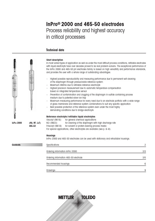
Specifications2Ordering information InPro 2000 2/3Ordering information 465-50 electrode 3/5Recommended housings 6Drawings9Contents InPro ® 2000 and 465-50 electrodes Process reliability and highest accuracy in critical processesTechnical dataInPro 2000(HA, HF, LoT)465-50Short descriptionIn most varied types of application as well as under the most difficult process conditions, refillable e lectrodes with liquid electrolyte have over decades proved to be real problem-solvers. The exceptional p erformance of the InPro 2000 and 465-50 pH electrodes family is based on high versatility and performance standards,and provides the user with a whole range of outstanding advantages:–Highest possible reproducibility and measuring performance due to permanent self-cleaning of the diaphragm through pressurizable reference system –Maximum lifetime due to refillable reference electrolyte–Highest precision measurement due to automatic temperature compensation based on integrated temperature sensor–Prevention of contamination and clogging of the diaphragm in sulfide containing process medium due to patented silver-ion trap–Maximum measuring performance for every need due to an electrode portfolio with a wide range of glass membrane and reference system combinations to suit any specific application –Best possible protection of the reference system even under the most highly demanding conditions due to bridge electrolyteReference electrolyte /refillable liquid electrolytes Viscolyt (9816)for general chemical applications KCl (9823)for cleaning of the diaphragm with high discharge rate Friscolyt (9818)for solvent or protein-bearing process media For special applications, other electrolytes are available (see p. 6–8).HousingsInPro 2000 and 465-50 electrodes can be used with stationary and retractable housings.SpecificationspH range InPro 2000: 0...14HA465-50: 0 (14)InPro 2001: 1...11465-50: 0 (12)InPro 2002: 1...11(HF, LoT)465-50:1 (11)Temperature range °C InPro 2000: 0…140 (32…284 °F)(HA) 465-50:0…130 (32…266 °F)InPro 2001: –30…80 (–22…176 °F)LoT 465-50:–30 80 (-22…176 °F)InPro 2002: 0…80 (32…176 °F)HF 465-50:0…80 (32…176 °F) Pressure resistance up to max. 6 bar (87 psi) overpressure at 130 °C (266 °F)Reference system Argenthal (Ag/AgCl)Reference electrolyte refillable liquid electrolytes:Viscolyt (9816) for general chemical applicationsKCl (9823) for self-cleaning of diaphragms with high outflowFriscolyt (9848)for solvent- or protein-containing process mediaDiaphragm1, 2 or 3 ceramic diaphragm(s)Viscolyt: 3 diaphragms Friscolyt: 2 diaphragms KCI: 1 diaphragm Glass membrane InPro 2000 and HA 465-50:alkaline-media resistant glassInPro 2001 and LoT 465-50:low-temperature glassInPro 2002 and HF 465-50:hydrofluoric acid resistant glassSeries 465-50:glass resistant to thermal sterilizationConnector InPro 2000 series: VarioPin (VP), (HA, HF, LoT) 465-50: S7IP68 Pg 13.5 threadEx certification Ex ia IIC T6/T5/T4/T3 Ga/Gb, SEV 14 ATEX 0168 X, IECEx SEV 14.0025Xfor the InPro 2000 seriesFM certification IS / I, II, III /Div 1/GR ABCDEFG /T6 for the InPro 2000 seriesPED certification Pressure Equipment Directive guidelines 97/23/EG,Art. 3, Para. 3, for the InPro 2000 SeriesSilver-ion trap InPro 2000 series: yes(HA, HF, LoT) 465-50: with SCdesignationSterilizable yesAutoclavable InPro 2000 series: yes465-50 series: noCIP-compliance yesOrdering information InPro 2000 Series–Designed for use in stirred vessels, tanks, open basins and pipes in the chemical industry under harsh processconditions, and now also for up to 6 bar (87 psi) overpressure.–Optimal measurement performance even in strong alkaline media thanks to a tried and tested special glassmembrane for applications in the field of chemical processes.InPro 2000/120/Pt100/9816120 (4.7")52 001 426InPro 2000/120/Pt100/9823120 (4.7")52 001 430InPro 2000/120/Pt100/9848120 (4.7")52 001 434InPro 2000/150/Pt100/9816150 (5.9")52 002 179InPro 2000/150/Pt100/9823150 (5.9")52 002 831InPro 2000/150/Pt100/9848150 (5.9")52 001 590InPro 2000/200/Pt100/9848200 (7.9")52 002 192InPro 2000/250/Pt100/9816250 (9.8")52 001 428InPro 2000/250/Pt100/9848250 (9.8")52 001 436InPro 2000/250/Pt100/9823250 (9.8")52 001 432InPro 2000/450/Pt100/9816450 (17.7")52 001 738InPro 2000/450/Pt100/9823450 (17.7")52 001 794InPro 2000/450/Pt100/9848450 (17.7")52 001 655InPro 2001/120/Pt100/9848120 (4.7")52 002 756InPro 2001/250/Pt100/9848250 (9.8")52 001 758InPro 2001/450/Pt100/9848450 (17.7")52 002 800InPro 2002/120/Pt100/9848120 (4.7")52 002 291InPro 2002/250/Pt100/9848250 (9.8")52 002 791with bridge electrolyteInPro 2000EB/120/Pt100/9816120 (4.7")52 002 756InPro 2000EB/250/Pt100/9823250 (9.8")52 002 510Temperature sensor Pt1000InPro 2000/120/Pt1000/9816120 (4.7")52 001 427InPro 2000/120/Pt1000/9823120 (4.7")52 001 431InPro 2000/120/Pt1000/9848120 (4.7")52 001 435InPro 2000/150/Pt1000/9816150 (5.9")52 001 704InPro 2000/150/Pt1000/9848150 (5.9")52 001 749InPro 2000/250/Pt1000/9816250 (9.8")52 001 429InPro 2000/250/Pt1000/9823250 (9.8")52 001 433InPro 2000/250/Pt1000/9848250 (9.8")52 001 437InPro 2000/450/Pt1000/9816450 (17.7")52 001 792InPro 2000/450/Pt1000/9823450 (17.7")52 001 777InPro 2000/450/Pt1000/9848450 (17.7")52 001 666InPro 2001/150/Pt1000/9848150 (5.9")52 002 542Ordering information Series: 465-50 with HA, HF, LoT– Designed for use in stirred vessels, tanks, open basins and pipes in the chemical industry under harsh processconditions, and now also for up to 6 bar (87 psi) overpressure.– Optimal measurement performance even in strong alkaline media thanks to a well-proven special membraneglass for applications in the field of chemical processes.HA465-50-SC-S7/120/9823120(4.7")10 465 4510IGHA465-50-SC-S7/150/9823150(5.9")10 465 4511IGHA465-50-SC-S7/250/9823250(9.8")10 465 4512IGHA465-50-SC-S7/450/9823450(17.7")10 465 4513IGHA465-50-SC-S7/200/9823200(7.9")10 465 4514IGHA465-50-SC-S7/250/9840250(9.8")10 465 4515IGHA465-50-SC-T-S7/450450(17.7")10 465 4517IGHA465-50-SC-P-S7/120/9848120(4.7")10 465 4519IGHA465-50-SC-P-S7/250/9848250(9.8")10 465 4522IGFor highest accuracy in critical processesInPro 2000 and HA, HF, LoT 465-50 electrodesHA465-50-SC-S7/120/9830120(4.7")10 465 4525IGHA465-50-SC-S7/250/9830250(9.8")10 465 4526IGHA465-50-SC-P-S7/150/9848150(5.9")10 465 4531IGHA465-50-SC-T-S7/120120(4.7")52 001 034HA465-50-SC-T-S7/150150(5.9")52 001 035HA465-50-SC-T-S7/200200(7.9")52 001 036HA465-50-SC-T-S7/250250(9.8")52 001 037with high-alkali glass and electrolyte bridgeHA465-50-90-T-S7/120120(4.7")10 465 4157IGHA465-50-90-T-S7/150150(5.9")10 465 4158IGHA465-50-90-T-S7/200200(7.9")10 465 4159IGHA465-50-90-T-S7/250250(9.8")10 465 4160IGHA465-50-90-T-S7/400400(15.8")11 465 3039IGHA465-50-90-T-S7/450450(17.7")52 001 038HA465-50-90-T-S7/120/9846120(4.7")11 465 3079IGHA465-50-90-T-S7/120/9813120(4.7")11 465 3081IGwith high-alkali glass and electrolyte bridgeHA465-50-90-T-S7/150/9813150(5.9")11 465 3183IGHA465-50-90-T-S7/250/9813250(9.8")52 000 717HA465-50-90-T-S7/250/9823/9823250(9.8")10 465 4527IGHA465-50-90-S7/120/9823-9823120(4.7")11 465 3077IGHA465-50-90-S7/150/9823/9823150(5.9")52 001 039HA465-50-90-S7/200/9823/9823200(7.9")52 001 040HA465-50-90-S7/250/9823/9823250(9.8")52 001 041HA465-50-90-S7/450/9823/9823450(17.7")52 001 042Sterilization-resistant glass465-50-S7/120120(4.7")10 465 3456IG465-50-S7/150150(5.9")10 465 3457IG465-50-S7/200200(7.9")10 465 3458IG465-50-S7/250250(9.8")10 465 3459IG465-50-S7/350350 (13.8")10 465 3461IG465-50-S7/470470 (18.5")10 465 4129IG465-50-S7/550550 (21.7")10 465 3465IG465-50-T-S7/120120(4.7")10 465 4493IG465-50-T-S7/150150(5.9")10 465 4452IG465-50-T-S7/200200(7.9")10 465 4488IG465-50-T-S7/250250(9.8")10 465 4483IG465-50-SC-P-S7/120/9848120(4.7")10 465 4500IG465-50-SC-P-S7/150/9848150(5.9")10 465 4501IG465-50-SC-P-S7/200/9848200(7.9")10 465 4502IG465-50-SC-P-S7/250/9848250(9.8")10 465 4503IG465-50-SC-P-S7/350/9848350 (13.8")11 465 3175IG465-50-SC-P-S7/450/9848450(17.7")10 465 4509IG465-50-SC-P-S7/520/9848520 (20.5")11 465 3176IG465-50-SC-P-S7/550/9848550 (21.7")11 465 3177IGSterilization-resistant glass and electrolyte bridge465-50-90-K9/120120(4.7")10 465 4022IG Array465-50-90-T-S7/200200(7.9")10 465 4149IGFor highest accuracy in critical processes InPro 2000 and HA, HF, LoT 465-50 electrodes465-50-90-T-S7/120120(4.7")10 465 4495IG465-50-90-S7/170170(6.7")11 465 3011IG465-50-90-T-S7/120/9849120(4.7")11 465 3026IGwith special glass membraneHF465-50-T-S7/450450(17.7")11 465 3174IGLoT465-50-T-S7/120/9848120(4.7")10 465 4164IGLoT465-50-T-S7/150/9848150(5.9")10 465 4173IGLoT465-50-T-S7/250/9848250(9.8")11 465 3053IGPt4865-50-SC-T-S7/150150(5.9")10 565 3088IGPt4865-50-SC-T-S7/200200(7.9")10 565 3089IGPt4865-50-SC-T-S7/250250(9.8")10 565 3090IGPt4865-50-SC-T-S7/450450(17.7")52 001 043Pt4865-50-SC-S7/120/9848120(4.7")10 5653 138IGPt4865-50-SC-S7/150/9848150(5.9")10 565 3137IGPt4865-50-SC-S7/170/9848170(6.7")11 565 3038IGPt4865-50-SC-S7/200/9848200(7.9")10 565 3139IGPt4865-50-SC-S7/250/9848250(9.8")10 565 3140IGPt4865-50-SC-P-S7/450/9848450(17.7")11 565 3041IGORP electrodes with electrolyte bridgePt4865-50-90-S7/120/9823-9823120(4.7")52 001 044Pt4865-50-90-S7/150/9823-9823150(5.9")52 001 045Pt4865-50-90-S7/200/9823-9823200(7.9")52 001 046Pt4865-50-90-S7/250/9823-9823250(9.8")52 001 047Pt4865-50-90-S7/450/9823-9823450(17.7")52 001 048Pt4865-50-90-T-S7/120/9848-9848120(4.7")10 565 3579IGPt4865-50-90-T-S7/150150(5.9")52 001 457Pt4865-50-90-T-S7/450450(17.7")11 565 3045IG AccessoriesVP6-ST/ 3 m ( 9.8 ft)52 300 108VP6-ST/ 5 m (16.4 ft)52 300 109VP6-ST/10 m (32.8 ft)52 300 110High temperature (–30…140 °C/–22…284 °F)VP6-HT/ 3 m ( 9.8 ft)52 300 112VP6-HT/ 5 m (16.4 ft)52 300 113VP6-HT/10 m (32.8 ft)52 300 114AS9/ 3 m ( 9.8 ft)10 001 0302AS9/ 5 m (16.4 ft)10 001 0502For highest accuracy in critical processes InPro 2000 and HA, HF, LoT 465-50 electrodespH 4.01 (red)51 340 057 51 340 05851 340 228pH 7.00 (green)51 340 059 51 340 06051 340 229pH 9.21 (blue)51 300 19351 300 19451 340 230Redox-Puffer +220mV51 340 06551 340 08151 319 021Redox-Puffer +468mV51 340 066Viscolyt 981651 340 23551 340 236–Friscolyt 984851 340 053 51 340 054–3 mol/l KCl 982351 340 049 51 340 050–LiCl in Ethanol 9830––51 319 051Calcolyt 984051 319 039 51 319 040––KNO3981351 340 047 51 340 234 ArrayElectrode cleaning solution51 340 06851 340 06951 319 041Diaphragm cleaning solution51 340 070 51 340 082–Regeneration solution51 340 073 (1 x 25 ml)51 319 053 (6 x 30 ml)Reactivation solution Array120 mm(4.7")InFit764e70 mm120 mm(4.7")InFit763e400 – 4000 mm150 mm(5.9")InFit763e400 – 4000 mm150 mm(5.9")InFit764e100 mm200 mm(7.9")InFit764e150 mm250 mm(9.8")InTrac776e70/100 mmInTrac796-M or P75 mmInFit 764e100 mm450 mm(17.7")InTrac776e200mmFor pipe installations, the above housings can be used in combination with InFlow 76X Flow-through housings.For highest accuracy in critical processes InPro 2000 and HA, HF, LoT 465-50 electrodesSelection guide pH range0…140…140…140…141…111…11mV mV0…12Temperature range °C 0…130 0…1300…1300…130 -30…800…80 0…1300…130 0…130Temperature range °F 32…26632…26632…26632…266-22…17632…17632…26632…26632…266Silver-ion-trap44––––4–4Reference electrolyteViscolyt KCl Viscolyt KCl/KCl Friscolyt Viscolyt Viscolyt KCl/KCl FriscolytApplicationsChemical processes generallysulfide containing media in particular44Boiler feed water, pharmaceutical processes,and at increased risk of diaphragm clogging 4Chemical processes in the presence of gases such as chlorine and hydrogen 4Problematic chemical processes requiring bridge electrolyte44Cooling water, blood plasma fractionation,and other low temperature applications 4Process media containing hydrofluoric acid44Applications in biotechnological processes,in particular in protein containing media 4Chemical process media mainly based on organic solvents9830*9830*9830*Sugar processing, citric acid production and at other CaCO 3precipitation risks 9840*9840*Media containing gypsum or metal oxide, with risk of sulfate precipitation9902*9902*Photo industry, latex paint industry and other media containing Hg 2+, Cu 2+, Ag +or Pb 2+ions sensitive to Cl - ions9813*9813** KCl to be replaced by the specified electrolyte.H A465-50-S C -T -S 7H A 465-50-S C -S 7/9823H A 465-50-90-T -S 7H A 465-50-90-S 7/9823/9823H F 465-50-T -S 7L o T 465-50-T -S 7-9848P t 4865-50-90-S 7/9823/9823465-50-S C -P -S 7P t 4865-50-S C -T -S 7Reference electrolyteA variety of different electrolytes are available to cover the widest range of applications in the chemical industry.Designation Order no.Order no.1 x 250 ml 6 x 250 ml9816 Viscolyt most frequently used CP electrolytewith limited outflow and thereforelong refill intervals 51 340 235 51 340 236 9823 KCl classic electrolyte with high electrolyteoutflow for improved diaphragmcleaning 51 319 023 51 319 024 9848 Friscolyt used for media with protein / organicsolvents content, and in low-temperatureapplications 51 340 053 51 340 054 9830 LiCl in ethanol used in chemical processes containingorganic solvents51 340 052 51 319 051 9840 Calcolyt used where there is a risk of calciumcarbonate precipitation 51 319 039 51 319 040 9813 KNO3used as bridge electrolyte where chlorideions interfere51 340 047 51 340 234Electrolyte bridgeBridge-type electrodes (-90-) offer optimal protection of the reference element in the most difficult applications.They are equipped with two concentric electrolyte chambers for bridge and reference electrolyte respectively, sepa-rated by an internal diaphragm.TransmittersA wide range of transmitters can be offered to complete the METTLER TOLEDO measurement system, including a4 wire version for universal AC/DC power supply, or alternatively in 2-wire versions, with HART®, FOUNDATION Field-bus or Profibus®communication, of standard or explosion-proof (EEx) design.Drawing1ConnectorProvides a safe industrial connection, allowi ng rapid demounting and remounting dur i ng maintenance procedures.2Electrolyte refill openingThe necessary refill interval depends on the number of diaphragms,their porosity, electrolyte viscosity (temperature-dependent) and the applied pressure difference. Examples of electrolyte outflow per 24hours at ∅P 2 bar and 25 °C (77 °F):3 M KCl: 2 ml per diaphragm Viscolyt:0.15 – 0.3 ml at 3 diaphragms Friscolyt:0.3 – 0.6 ml at 3 diaphragms 3Reference elementsArgenthal reference elements deliver stable potential and therefore reliable pH values at temperatures up to 130 °C. (266 °F)4Argenthal with SC The additional patented silver-ion trap efficiently protects the diaphragm from silver sulfide precipitations in sulfide-containing media.Equithal reference elements have up to 10 times shorter response times in processes with rapidly changing temperatures.5Ceramic diaphragm(s)Through their pores, ceramic diaphragms provide the required liquid junction between the measurement solution and the reference ele-ment via the reference electrolyte.465-50 sensor versions are availa-ble with 1, 2 or 3 diaphragms, but in the chemical process industry predominantly those with 3 diaphragms (-T-) are used6pH sensitive glassHA high-alkali glass assures reliable measurements over the whole range pH 0–14.LoT glass is particularly suitable for measurements at low temperatu-res (down to minus 30 °C (-22 °F).HF glass offers increased resistance against media containing hydro-fluoric acid (see table):at pH 2 and 20 °C: (68 °F)HF < 300 ppm at pH 3 and 20 °C: HF < 1000 ppm at pH 4 and 20 °C: HF < 6000 ppm at pH > 5: no F - concentration limit 7Platinum ringApplicable to redox sensors.8Temperature sensorThe built in temperature sensor (Pt 100 or Pt 1000) is located behind the pH glass and allows for the automatic compensation.InPro 2000 HA, HF, LoT 465-501286543aØ 32 mm (1.26")Ø 12 mm (0.47")METTLER TOLEDO Market OrganizationsSubject to technical changes.© Mettler-Toledo AG, 05/2015Printed in Switzerland. 52 002 969Management Systemcertified according toISO 9001 / ISO 14001Mettler-Toledo AG, Process Analytics Im Hackacker 15, CH -8902 UrdorfPhone +41 44 729 62 11, Fax +41 44 729 66 36Sales and Service:AustraliaMettler-Toledo Ltd.220 Turner Street Port MelbourneAUS -3207 Melbourne /VIC Phone +61 1300 659 761Fax +61 3 9645 3935e-mail *****************AustriaMettler-Toledo Ges.m.b.H.Südrandstraße 17A -1230 WienPhone +43 1 604 19 80Fax +43 1 604 28 80e-mail ***********************BrazilMettler-Toledo Ind. e Com. Ltda.Avenida Tamboré, 418TamboréBR -06460-000 Barueri /SP Tel.+55 11 4166 7400Fax +55 11 4166 7401e-mail *******************.br*******************.br ChinaMettler-Toledo Instruments (Shanghai) Co. Ltd.589 Gui Ping Road Cao He JingCN -200233 ShanghaiPhone +86 21 64 85 04 35Fax +86 21 64 85 33 51e-mail *************** CroatiaMettler-Toledo d.o.o.Mandlova 3HR -10000 ZagrebPhone +385 1 292 06 33Fax +385 1 295 81 40e-mail ****************Czech Republic Mettler-Toledo s.r.o.Trebohosticka 2283/2CZ -100 00 Praha 10Phone +420 2 72 123 150Fax +420 2 72 123 170e-mail *****************DenmarkMettler-Toledo A /S Naverland 8DK -2600 GlostrupPhone +45 43 27 08 00Fax +45 43 27 08 28e-mail ****************FranceMettler-ToledoAnalyse Industrielle S.A.S.30, Boulevard de Douaumont F -75017 ParisPhone +33 1 47 37 06 00Fax +33 1 47 37 46 26e-mail **************GermanyMettler-Toledo GmbH Prozeßanalytik Ockerweg 3D -35396 GießenPhone +49 641 507 444Fax +49 641 507 397e-mail **************Great BritainMettler-Toledo LTD64 Boston Road, Beaumont Leys GB -Leicester LE4 1AWPhone +44 116 235 7070Fax +44 116 236 5500e-mail *******************HungaryMettler-Toledo Kereskedelmi KFT Teve u. 41HU -1139 BudapestPhone +36 1 288 40 40Fax +36 1 288 40 50e-mail ***************IndiaMettler-Toledo India Private Limited Amar Hill, Saki Vihar Road PowaiIN -400 072 MumbaiPhone +91 22 2857 0808Fax +91 22 2857 5071e-mail *****************ItalyMettler-Toledo S.p.A.Via Vialba 42I -20026 Novate Milanese Phone +39 02 333 321Fax +39 02 356 2973e-mail**************************JapanMettler-Toledo K.K.Process Division6F Ikenohata Nisshoku Bldg.2-9-7, Ikenohata Taito-kuJP -110-0008 TokyoPhone +81 3 5815 5606Fax +81 3 5815 5626e-mail **********************MalaysiaMettler-Toledo (M) Sdn BhdBangunan Electroscon Holding, U 1-01Lot 8 Jalan Astaka U8/84Seksyen U8, Bukit JelutongMY -40150 Shah Alam Selangor Phone +60 3 78 44 58 88 Fax +60 3 78 45 87 73e-mail****************************MexicoMettler-Toledo S.A. de C.V.Ejercito Nacional #340Col. Chapultepec Morales Del. Miguel Hidalgo MX -11570 México D.F.Phone +52 55 1946 0900e-mail *****************PolandMettler-Toledo (Poland) Sp.z.o.o.ul. Poleczki 21PL -02-822 WarszawaPhone +48 22 545 06 80Fax +48 22 545 06 88e-mail *************RussiaMettler-Toledo Vostok ZAO Sretenskij Bulvar 6/1Office 6RU -101000 MoscowPhone +7 495 621 56 66Fax +7 495 621 63 53e-mail **************SingaporeMettler-Toledo (S) Pte. Ltd.Block 28Ayer Rajah Crescent #05-01SG -139959 Singapore Phone +65 6890 00 11Fax +65 6890 00 12+65 6890 00 13e-mail ****************SlovakiaMettler-Toledo s.r.o.Hattalova 12/ASK -83103 BratislavaPhone +421 2 4444 12 20-2Fax +421 2 4444 12 23e-mail *************SloveniaMettler-Toledo d.o.o.Pot heroja Trtnika 26SI -1261 Ljubljana-Dobrunje Phone +386 1 530 80 50Fax +386 1 562 17 89e-mail *******************South KoreaMettler-Toledo (Korea) Ltd.Yeil Building 1 & 2 F 124-5, YangJe-Dong SeCho-KuKR -137-130 SeoulPhone +82 2 3498 3500Fax +82 2 3498 3555e-mail *****************SpainMettler-Toledo S.A.E.C /Miguel Hernández, 69-71ES -08908 L’Hospitalet de Llobregat (Barcelona)Phone +34 902 32 00 23Fax +34 902 32 00 24e-mail *************SwedenMettler-Toledo AB Virkesvägen 10Box 92161SE -12008 StockholmPhone +46 8 702 50 00Fax +46 8 642 45 62e-mail ****************SwitzerlandMettler-Toledo (Schweiz) GmbH Im Langacher PostfachCH -8606 GreifenseePhone +41 44 944 45 45Fax +41 44 944 45 10e-mail ******************ThailandMettler-Toledo (Thailand) Ltd.272 Soi Soonvijai 4Rama 9 Rd., Bangkapi Huay KwangTH -10320 BangkokPhone +66 2 723 03 00Fax +66 2 719 64 79e-mail****************************USA /Canada METTLER TOLEDO Process Analytics900 Middlesex Turnpike, Bld. 8Billerica, MA 01821, USA Phone +1 781 301 8800Freephone +1 800 352 8763Fax +1 781 271 0681e-mail **************。
爱士顿199158产品目录号199158爱士顿摩尔系列PKZM0电动机保护电路断路器,5.5 kW,

Eaton 199158Eaton Moeller® series PKZM0 Motor-protective circuit-breaker, 5.5kW, 8 - 12 A, Push in terminalsSpécifications généralesEaton Moeller® series PKZM0 Motor-protective circuit-breaker199158401508197242575 mm109 mm45 mm0.348 kgIEC/EN 60947VDE 0660ULCSAIEC/EN 60947-4-1UL 60947-4-1CSA-C22.2 No. 60947-4-1-14 CEUL File No.: E36332UL Category Control No.: NLRV CSA File No.: 165628CSA Class No.: 3211-05PKZM0-12-PIProduct Name Catalog NumberEANProduct Length/Depth Product Height Product Width Product Weight Certifications Model CodeTurn buttonPhase-failure sensitivity (according to IEC/EN 60947-4-1, VDE 0660 Part 102)Motor protectionPhase failure sensitiveThree-pole 100,000 operations100,000 OperationsDIN rail (top hat rail) mounting optionalCan be snapped on to IEC/EN 60715 top-hat rail with 7.5 or15 mm height.40 Operations/hIII3Motor protective circuit breakerFinger and back-of-hand proof, Protection against direct contact when actuated from front (EN 50274)6000 V AC25 g, Mechanical, according to IEC/EN 60068-2-27, Half-sinusoidal shock 10 msAlso motors with efficiency class IE3Branch circuit: Manual type E if used with terminal, or suitable for group installations, (UL/CSA)-5 - 40 °C to IEC/EN 60947, VDE 0660-25 - 55 °C, Operating range≤ 0.25 %/K, residual error for T > 40°Actuator type Features Functions Number of poles Lifespan, electricalLifespan, mechanicalMounting MethodMounting positionOperating frequencyOvervoltage categoryPollution degreeProduct categoryProtectionRated impulse withstand voltage (Uimp) Shock resistanceSuitable forTemperature compensationAltitude Terminal capacity (flexible)Max. 2000 m-25 °C55 °C25 °C40 °C40 °C80 °CDamp heat, constant, to IEC 60068-2-78 Damp heat, cyclic, to IEC 60068-2-301 x (1 - 6) mm²18 - 812 mm50 Hz60 Hz12 A3 kW5.5 kW690 V690 V12 A18 kA, 600 V High Fault, Fuse, SCCR (UL/CSA)600 A, 600 V High Fault, max. Fuse, SCCR (UL/CSA) 18 kA, 600 V High Fault, CB, SCCR (UL/CSA)600 A, 600 V High Fault, max. CB, SCCR (UL/CSA)18 kA, 240 V, SCCR (UL/CSA)18 kA, 480 Y/277 V, SCCR (UL/CSA)18 kA, 600 Y/347 V, SCCR (UL/CSA)65 kA, 240 V, SCCR (UL/CSA)65 kA, 480 Y/277 V, SCCR (UL/CSA)0.5 HP 3 HP2 HP3 HP 7.5 HPAmbient operating temperature - minAmbient operating temperature - maxAmbient operating temperature (enclosed) - min Ambient operating temperature (enclosed) - max Ambient storage temperature - minAmbient storage temperature - maxClimatic proofing Terminal capacity (solid/stranded AWG)Stripping length (main cable)Rated frequency - minRated frequency - maxRated operational current (Ie)Rated operational power at AC-3, 220/230 V, 50 Hz Rated operational power at AC-3, 380/400 V, 50 Hz Rated operational voltage (Ue) - minRated operational voltage (Ue) - maxRated uninterrupted current (Iu)Short-circuit current rating (group protection) Short-circuit current rating (type E)Short-circuit release Assigned motor power at 115/120 V, 60 Hz, 1-phase Assigned motor power at 200/208 V, 60 Hz, 3-phase Assigned motor power at 230/240 V, 60 Hz, 1-phase Assigned motor power at 230/240 V, 60 Hz, 3-phase Assigned motor power at 460/480 V, 60 Hz, 3-phaseBasic device fixed 15.5 x Iu, Trip Blocks186 A, Irm, Setting range max.± 20% tolerance, Trip blocks10 HPPush in terminals0 0 012 A12 AOverload trigger: tripping class 10 A6.64 W0 W0 W0 WMeets the product standard's requirements. Meets the product standard's requirements. Meets the product standard's requirements. Meets the product standard's requirements. Meets the product standard's requirements.DA-DC-00004919.pdfDA-DC-00004889.pdfETN.PKZM0-12-PI.edzIL122024ZUpkzm0_pi.stpmotorschutzschalter_bis_32a_pi.dwg121X002121X042eaton-manual-motor-starters-pkzm-pkzm0-dimensions.eps eaton-manual-motor-starters-pkz-dimensions-002.eps eaton-manual-motor-starters-pkz-dimensions.eps Assigned motor power at 575/600 V, 60 Hz, 3-phase ConnectionNumber of auxiliary contacts (change-over contacts) Number of auxiliary contacts (normally closed contacts) Number of auxiliary contacts (normally open contacts)Overload release current setting - min Overload release current setting - max Tripping characteristicEquipment heat dissipation, current-dependent PvidHeat dissipation capacity PdissHeat dissipation per pole, current-dependent PvidStatic heat dissipation, non-current-dependent Pvs10.2.2 Corrosion resistance10.2.3.1 Verification of thermal stability of enclosures10.2.3.2 Verification of resistance of insulating materials to normal heat10.2.3.3 Resist. of insul. mat. to abnormal heat/fire by internal elect. effects10.2.4 Resistance to ultra-violet (UV) radiation Declarations of conformity eCAD model Instructions d'installation mCAD modelSchémas10.2.5 LiftingDoes not apply, since the entire switchgear needs to be evaluated.10.2.6 Mechanical impactDoes not apply, since the entire switchgear needs to be evaluated.10.2.7 InscriptionsMeets the product standard's requirements.10.3 Degree of protection of assembliesDoes not apply, since the entire switchgear needs to be evaluated.10.4 Clearances and creepage distancesMeets the product standard's requirements.10.5 Protection against electric shockDoes not apply, since the entire switchgear needs to be evaluated.10.6 Incorporation of switching devices and components Does not apply, since the entire switchgear needs to be evaluated.10.7 Internal electrical circuits and connectionsIs the panel builder's responsibility.10.8 Connections for external conductorsIs the panel builder's responsibility.10.9.2 Power-frequency electric strengthIs the panel builder's responsibility.10.9.3 Impulse withstand voltageIs the panel builder's responsibility.10.9.4 Testing of enclosures made of insulating materialIs the panel builder's responsibility.10.10 Temperature riseThe panel builder is responsible for the temperature rise calculation. Eaton will provide heat dissipation data for the devices.10.11 Short-circuit ratingIs the panel builder's responsibility. The specifications for the switchgear must be observed.10.12 Electromagnetic compatibilityIs the panel builder's responsibility. The specifications for the switchgear must be observed.Eaton Corporation plc Eaton House30 Pembroke Road Dublin 4, Ireland © 2023 Eaton. Tous droits réservés. Eaton is a registered trademark.All other trademarks areproperty of their respectiveowners./socialmediaThe device meets the requirements, provided the information in the instruction leaflet (IL) is observed.10.13 Mechanical function。
50N60场效应管资料

UNISONIC TECHNOLOGIES CO., LTD50N06MOSFET50 Amps, 60 VoltsN-CHANNEL POWER MOSFETDESCRIPTIONThe UTC 50N06 is three-terminal silicon device with current conduction capability of about 50A, fast switching speed. Low on-state resistance, breakdown voltage rating of 60V, and max threshold voltages of 4 volt.It is mainly suitable electronic ballast, and low power switching mode power appliances.FEATURES* R DS(ON) = 23m Ω@V GS = 10 V* Ultra low gate charge ( typical 30 nC )* Low reverse transfer Capacitance ( C RSS = typical 80 pF ) * Fast switching capability* 100% avalanche energy specified * Improved dv/dt capabilitySYMBOL1.GateTO-22011TO-220F*Pb-free plating product number: 50N06LORDERING INFORMATIONOrder Number Pin AssignmentNormalLead Free Plating Package 1 2 3 Packing50N06-TA3-T 50N06L-x-TA3-T TO-220 G D S Tube 50N06-TF3-T 50N06L-x-TF3-T TO-220F G D S TubeABSOLUTE MAXIMUM RATINGSPARAMETER SYMBOL RATINGS UNITDrain-Source Voltage V DSS 60 V Gate to Source Voltage V GSS ±20 VT C = 25 50 AContinuous Drain Current T C = 100 I D35 ADrain Current Pulsed (Note 1) I DM 200 A Single Pulsed Avalanche Energy (Note 2) E AS 480 mJ Repetitive Avalanche Energy (Note 1) E AR 13 mJ Peak Diode Recovery dv/dt (Note 3) dv/dt 7 V/nsTotal Power Dissipation (T C = 25 ) 130 WDerating Factor above 25P D0.9 W/ Operation Junction Temperature T J -55 ~ +150 Storage Temperature T STG -55 ~ +150 Note: Absolute maximum ratings are those values beyond which the device could be permanently damaged.Absolute maximum ratings are stress ratings only and functional device operation is not implied.THERMAL DATAPARAMETER SYMBOL MIN TYP MAX UNITThermal Resistance, Junction-to-Case θJC 1.15 °C/W Thermal Resistance, Case-to-Sink θCS 0.5 °C/W Thermal Resistance, Junction-to-Ambient θJA 62.5 °C/WELECTRICAL CHARACTERISTICS T C = 25 unless otherwise specifiedPARAMETER SYMBOL TEST CONDITIONS MIN TYP MAX UNIT Off CharacteristicsDrain-Source Breakdown Voltage BV DSS V GS = 0 V, I D = 250 µA 60 V Breakdown Voltage Temperature Coefficient BV DSS /△T J I D = 250 µA,Referenced to 250.07 V/V DS = 60 V, V GS = 0 V µADrain-Source Leakage Current I DSSV DS = 48 V, T C = 1251 µA Gate-Source Leakage Current V GS = 20V, V DS = 0 V 100 nAGate-Source Leakage Reverse I GSSV GS = -20V, V DS = 0 V -100 nA On Characteristics Gate Threshold Voltage V GS(TH) V DS = V GS , I D = 250 µA 2.0 4.0 V Static Drain-Source On-StateResistanceR DS(ON) V GS = 10 V, I D = 25 A 18 23 m ΩDynamic Characteristics Input Capacitance C ISS 900 1220 pFOutput Capacitance C OSS 430 550 pFReverse Transfer Capacitance C RSSV GS = 0 V, V DS = 25 Vf = 1MHz80 100 pF Dynamic Characteristics Turn-On Delay Time t D(ON) 40 60 nsRise Time t R 100 200 ns Turn-Off Delay Time t D(OFF) 90 180 nsFall Time t F V DD = 30V, I D =25 A, R G = 50Ω (Note 4, 5) 80 160 ns Total Gate Charge Q G 30 40 nCGate-Source Charge Q GS 9.6 nCGate-Drain Charge (Miller Charge) Q GD V DS = 48V, V GS = 10 VI D = 50A, (Note 4, 5)10 nC2. L=5.6mH, I AS=50A, V DD=25V, R G=0Ω, Starting T J=253. I SD≤50A, di/dt≤300A/µs, V DD≤BV DSS, Starting T J=254. Pulse Test: Pulse Width≤300µs,Duty Cycle≤2%5. Essentially independent of operating temperature.TEST CIRCUITS AND WAVEFORMSV DDV GS (Driver)I SD (D.U.T.)Body DiodeForward Voltage DropV DS(D.U.T.)Fig. 1A Peak Diode Recovery dv/dt Test CircuitFig. 1B Peak Diode Recovery dv/dt WaveformsTEST CIRCUITS AND WAVEFORMS (Cont.)R LDDV DS90%10%V GStFig. 2A Switching Test Circuit Fig. 2B Switching WaveformsFig. 3A Gate Charge Test CircuitFig. 3B Gate Charge Waveform10VLV DDI ASFig. 4A Unclamped Inductive Switching Test Circuit Fig. 4B Unclamped Inductive Switching WaveformsTYPICAL CHARACTERISTICS101010101010Drain -Source Voltage , V DS (V)D r a i n C u r r e n t , I D (A )On-State Characteristics101010Gate-Source Voltage , V GS (V)D r a i n C u r r e n t , I D (A )Transfer Characteristics0D r a i n -S o u r c e O n -R e s i s t a n c e , R D S (O N ) (m Ω)Drain Current , I D (A)4080200100140On-Resistance Variation vs . Drain Current102101000.2Source-Drain Voltage , V SD (V)R e v e r s e D r a i n C u r r e n t , I S D (A )On State Current vs. Allowable CaseTemperature1.60.40.60.8 1.0 1.2 1.420601201601805Drain -Source Voltage, V DC (V)C a p a c i t a n c e (p F )Capacitance Characteristics1020G a t e -t o -S o u r c e V o l t a g e , V G S (V )Total Gate Charge , Q G (nC)81012Gate Charge Characteristics64015253035TYPICAL CHARACTERISTICS(Cont.)-100D r a i n -S o u r c e B r e a k d o w n V o l t a g e , B V D S S (N o r m a l i z e d )Junction Temperature , T J (℃)-5050200100150Breakdown Voltage Variation vs . Junction, -5050100150On-Resistance Variation vs . 0Junction Temperature , T J (℃)101010Drain-Source Voltage , V DS (V)D r a i n C u r r e n t , I D ,(A )Maximum Safe Operating1010D r a i n C u r r e n t , I D (A )Case Temperature, T C (℃)7510050Maximum Drain Current vs . Case Temperature 01255025102030401010101010Square Wave Pulse Duration , t 1 (sec)T h e r m a l R e s p o n s e , Z θJ C (t )1010101010101010101Transient Thermal。
美国Eaton公司HFD1060L系列完整模块式电路保护器说明说明书
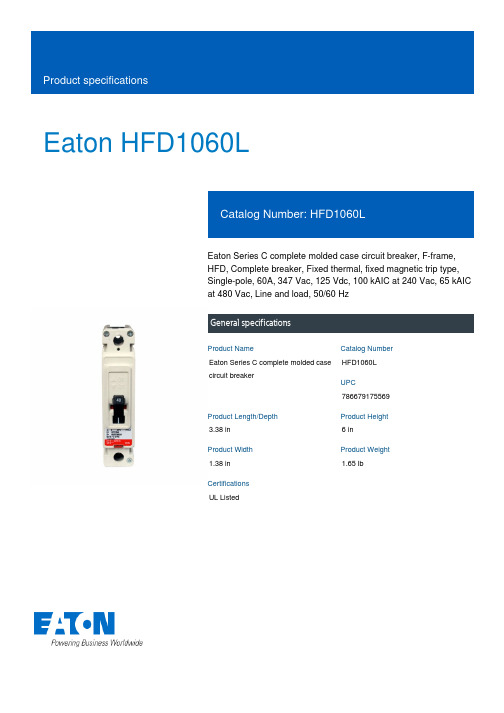
Eaton HFD1060LEaton Series C complete molded case circuit breaker, F-frame, HFD, Complete breaker, Fixed thermal, fixed magnetic trip type, Single-pole, 60A, 347 Vac, 125 Vdc, 100 kAIC at 240 Vac, 65 kAIC at 480 Vac, Line and load, 50/60 HzGeneral specificationsEaton Series C complete molded case circuit breakerHFD1060L 7866791755693.38 in 6 in1.38 in 1.65 lbUL ListedProduct NameCatalog Number UPCProduct Length/Depth Product Height Product Width Product Weight CertificationsSeries C65 kAIC at 480 Vac100 kAIC at 240 VacFHFD50/60 HzComplete breakerLine and load347 Vac, 125 Vdc60 AFixed thermal, fixed magnetic Single-pole Application of Multi-Wire Terminals for Molded Case Circuit Breakers Application of Tap Rules to Molded Case Breaker TerminalsUL listed 100%-rated molded case circuit breakersCircuit breaker motor operators product aidPlug-in adapters for molded case circuit breakers product aidMulti-wire lugs product aidStrandAble terminals product aidCurrent limiting Series C molded case circuit breakers product aid MOEM MCCB Product Selection GuidePower metering and monitoring with Modbus RTU product aidMotor protection circuit breakers product aidCounterfeit and Gray Market Awareness GuideBreaker service centersMolded case circuit breakers catalogEaton's Volume 4—Circuit ProtectionHFD1 2D PDFHFD1 3D Model XchangeHFD1 3D InventorTime Current Curves for Series C® F-Frame Circuit BreakersHFD1 AutoCAD 2D Footprint (mm)Installation Instructions for EHD, EDB, EDS, ED, EDH, EDC, FDB, FD, HFD, FDC, HFDDC Circuit Breakers and Molded Case SwitchesCircuit Breakers ExplainedCircuit breakers explainedMOEM MCCB product selection guideSeries C G-Frame molded case circuit breakers time current curves Eaton Specification Sheet - HFD1060LSeries C J-Frame molded case circuit breakers time current curves Series C F-Frame molded case circuit breakersSeriesInterrupt ratingFrameCircuit breaker type Frequency ratingCircuit breaker frame type TerminalsVoltage rating Amperage RatingTrip TypeNumber of poles Application notesBrochuresCatalogsDrawingsInstallation instructions MultimediaSpecifications and datasheetsEaton Corporation plc Eaton House30 Pembroke Road Dublin 4, Ireland © 2023 Eaton. All Rights Reserved. Eaton is a registered trademark.All other trademarks areproperty of their respectiveowners./socialmedia。
朗纳公司60赫兹标准负载电机包装并行驱动套件安装、维护和零件手册说明书

For other service manuals visit our website at:/service_manuals.aspDORNER MFG. CORP .INSIDE THE USA OUTSIDE THE USA P .O. Box 20 • 975 Cottonwood Ave.TEL: 1-800-397-8664TEL: 262-367-7600Hartland, WI 53029-0020 USAFAX: 1-800-369-2440FAX: 262-367-5827851-528 Rev. D3200 & LPZ Series Bottom Mount Parallel Drive Package for Standard Load 60 HzGearmotorsInstallation, Maintenance & Parts ManualDorner Mfg. Corp.2851-528 Rev. D3200 & LPZ Series Bottom Mount Parallel Drive Package for Standard Load 60 Hz GearmotorsTable of ContentsIntroduction......................................................................... 2Warnings - General Safety.................................................. 3Product Description............................................................. 4Specifications...................................................................... 4Installation........................................................................... 7Required Tools................................................................. 7Mounting.......................................................................... 7Preventive Maintenance and Adjustment............................ 9Required Tools................................................................. 9Timing Belt Tensioning (9)Timing Belt Replacement................................................. 9Drive or Driven Pulley Replacement............................. 10Motor Replacement........................................................ 10Service Parts....................................................................... 123200 Series Conveyors Bottom Mount Parallel Drive Package for Standard Load Industrial Gearmotors........ 123200 Standard Load Parallel Shaft IndustrialGearmotors..................................................................... 13Return Policy. (14)IntroductionUpon receipt of shipment:•Compare shipment with packing slip. Contact factory regarding discrepancies.•Inspect packages for shipping damage. Contact carrier regarding damage.•Accessories may be shipped loose. See accessory instruc-tions for installation.Dorner 3200 Series conveyors are covered by patentnumbers 5156260, 5156261, 5203447, 5265714 and patent applications in other countries.Dorner LPZ Series conveyors are covered by patent numbers 5156260, 5156261, 5203447, 5265714, 5875883 and patent applications in other countries.Dorner’s Limited Warranty applies.Dorner reserves the right to make changes at any time without notice or obligation.Dorner has convenient, pre −configured kits of Key Service Parts for all conveyor products. These time saving kits are easy to order, designed for fast installation, and guarantee you will have what you need when you need it. Key Parts and Kits are marked in the Service Parts section of this manual with the Performance Parts Kits logo.IMPORTANTSome illustrations may show guards removed. DO NOT operate equipment without guards.851-528 Rev. D3Dorner Mfg. Corp.3200 & LPZ Series Bottom Mount Parallel Drive Package for Standard Load 60 Hz GearmotorsWarnings - General SafetyA WARNINGThe safety alert symbol, black triangle with white exclamation, is used to alert you to potential personal injury hazards.Climbing, sitting, walking or riding on conveyor will cause severe injury.KEEP OFF CONVEYORS.DO NOT OPERATE CONVEYORS IN AN EXPLOSIVE ENVIRONMENT.A WARNINGExposed moving parts can cause severe injury.LOCK OUT POWER before removing guards or performing maintenance.A WARNINGGearmotors may be HOT.DO NOT TOUCH Gearmotors.A WARNINGExposed moving parts can cause severe injury.REPLACE ALL GUARDS BEFORE RUNNING CONVEYOR.A WARNINGDorner cannot control the physicalinstallation and application of conveyors. Taking protective measures is the responsibility of the user.When conveyors are used in conjunction with other equipment or as part of a multiple conveyor system, CHECK FOR POTENTIAL PINCH POINTS and other mechanical hazards before system start-up.Dorner Mfg. Corp.4851-528 Rev. D3200 & LPZ Series Bottom Mount Parallel Drive Package for Standard Load 60 Hz GearmotorsProduct DescriptionRefer to Figure 1 for typical components. Figure 1SpecificationsGearmotor Mounting Package Models:Example:A ConveyorB Mounting BracketC GearmotorD Timing Belt TensionerE CoverF Timing BeltG Drive Pulley HDriven PulleyAEF GCBH D851-528 Rev. D5Dorner Mfg. Corp.3200 & LPZ Series Bottom Mount Parallel Drive Package for Standard Load 60 Hz GearmotorsSpecificationsTable 1: Gearmotor SpecificationsTable 2: Belt Speeds for Fixed Speed Parallel Shaft 60 Hz Gearmotors(vp) = voltage and phase 11 = 115 V , 1-phase23 = 208 – 230/460 V , 3-phaseSingle PhaseThree Phase DC Variable SpeedVFD Variable SpeedPower/ Gear Ratiohp (kW)hp (kW)hp (kW)hp (kW)5:1.08 (.06).17 (.13).12 (.09).17 (.13)10:1.17 (.13).17 (.13).25 (.19).17 (.13)20:1.33 (.25).38 (.28).25 (.19).38 (.28)30:1.33 (.25).38 (.28).25 (.19).38 (.28)60:1.33 (.25).38 (.28).33 (.25).38 (.28)180:1.33 (.25).38 (.28)N/A .38 (.28)Input Voltage 115 VAC 230 VAC 130 VDC 230 VAC Input Frequency 60 Hz 60 Hz N/A 10 to 60 HzInput Current/ Gear Ratio FLA FLA FLA FLA 5:1 1.2 1.0 1.0 1.010:1 1.9 1.0 1.8 1.020:14 1.9 1.8 1.930:14 1.9 1.8 1.960:14 1.9 2.3 1.9180:14 1.9N/A 1.9Motor RPM 1725172525001725Power/RatioTotally EnclosedFan CooledTotally Enclosed Non–VentilatedTotally Enclosed FanCooledStandard Load GearmotorsBelt SpeedDrive PulleyDriven Pulley Part Number RPM In-lb N-m Ft/min M/min 62M180PS4vpFn 1022625.57.6 2.3161662M180PS4vpFn 1022625.511.4 3.5241662M060PS4vpFn 2923726.822.97.0161632M030PS4vpFn 5814216.045.814.0161632M020PS4vpFn 86788.868.620.9161632M020PS4vpFn 86788.8103.031.4241632M010PS4vpFn 17341 4.6137.341.9161632M010PS4vpFn 17341 4.6171.652.3201632M010PS4vpFn 17341 4.6205.962.8241632M005PS4vpFn 34541 4.6274.683.7161632M005PS4vpFn 34541 4.6343.2104.6201632M005PS4vpFn345414.6411.9125.62416Dorner Mfg. Corp.6851-528 Rev. D3200 & LPZ Series Bottom Mount Parallel Drive Package for Standard Load 60 Hz GearmotorsSpecificationsTable 3: Belt Speeds for Variable Speed Parallel Shaft VFD GearmotorsTable 4: Belt Speeds for Variable Speed Parallel Shaft DC GearmotorsStandard Load GearmotorsBelt SpeedDrive Pulley Driven Pulley Part Number RPM In-lb N-m Ft/min M/min 62M180PS4vpFn 1022625.5 1.3−7.60.4−2.3161662M060PS4vpFn 2923726.8 3.8−22.9 1.2−7.0161632M030PS4vpFn 5814216.07.6−45.8 2.3−14.0161632M020PS4vpFn 86788.811.5−68.6 3.5−20.9161632M020PS4vpFn 86788.817.2−103. 0 5.2−31.4241632M010PS4vpFn 17341 4.622.9−137. 37.0−41.9161632M010PS4vpFn 17341 4.634.4−205. 910.5−62.8241632M005PS4vpFn 34541 4.645.9−274. 614.0−83.7161632M005PS4vpFn 34541 4.657.3−343. 217.5−104. 6201632M005PS4vpFn345414.668.8−411. 921.0−125. 62416Standard Load GearmotorsBelt SpeedDrive Pulley Driven Pulley Part Number RPM In-lb N-m Ft/min M/min 62M180PSD3DEN 1422625.5 1.3−11.10.4−3.4161662M180PSD3DEN 1422625.5 2.0−16.60.6−5.1241662M060PSD3DEN 4223726.8 4.0−33.2 1.2−10.1161662M030PSD3DEN 8314216.08.0−66.3 2.4−20.2161662M020PSD3DEN 125788.811.9−99.5 3.6−30.3161662M020PSD3DEN 125788.817.9−149.2 5.5−45.5241662M010PSD3DEN 25041 4.623.9−199.07.3−60.7161662M010PSD3DEN 25041 4.629.8−248.79.1−75.8201662M010PSD3DEN250414.635.8−298.510.9−91.02416NOTEFor belt speed other than those listed, contact factory for details.851-528 Rev. D7Dorner Mfg. Corp.3200 & LPZ Series Bottom Mount Parallel Drive Package for Standard Load 60 Hz GearmotorsInstallationRequired Tools•Hex key wrenches:2 mm, 2.5 mm,3 mm, 5 mm •Straight edge •Torque wrenchMountingInstallation Component List:1.Typical components (Figure 2)Figure 22.Locate drive output shaft (Figure 3,item Q). Remove two (2) M8 screws (P) and four (4) M6 screws (O) and discard.Figure 33.Attach bottom mount drive assembly (Figure 4,item B) with two (2) M8 screws (M) and four (4) M6 screws (L). Tighten M6 screws (L) to 146 in −lbs (16.5 N −m) and M8 screws (M) to 288 in −lbs (32.5 N −m).Figure 44.Install key (Figure 5,itemK).AWARNINGExposed moving parts can cause severe injury.LOCK OUT POWER before removing guards or performing maintenance.E CoverF Timing BeltG Drive PulleyH Driven PulleyI Bottom Mount Drive Assembly J Cover Screws K KeyL M6 Socket Head Screws (4x)M M8 Socket Head Screws (2x)N TensionerLHEFGKMIJNNOTECleated belt mounting package shown, flat belt mounting package similar.A WARNINGDrive shaft keyway may be sharp.HANDLE WITH CARE.QPOOBMLDorner Mfg. Corp.8851-528 Rev. D3200 & LPZ Series Bottom Mount Parallel Drive Package for Standard Load 60 Hz GearmotorsInstallationFigure 55.Wrap timing belt (F) around driven pulley (H) and drive pulley (G). Install driven pulley (H) onto conveyor shaft.6.Using a straight edge (Figure 6,item R), align driven pulley (H) with drive pulley (G). Tighten driven pulley taper-lock screws (Figure 7,item S).Figure 6Figure 77.Depending on conveyor belt travel (direction 1 or 2), locate timing belt tensioner (Figure 8,item N) as shown. Tension timing belt to obtain 1/8” (3 mm) deflection for 6 lb (3 Kg) of force at timing belt mid-point (T). Tighten tensioner screw to 110 in-lb (12 Nm).Figure 88.Install cover (Figure 9,item E) with four (4) screws (J). Tighten screws to 35 in-lb (4 Nm).Figure 9K H FGHR GS12TTNEJJ851-528 Rev. D9Dorner Mfg. Corp.3200 & LPZ Series Bottom Mount Parallel Drive Package for Standard Load 60 Hz GearmotorsPreventive Maintenance and AdjustmentRequired Tools•Hex key wrenches:2 mm, 2.5 mm,3 mm, 5 mm•Adjustable wrench (for hexagon head screws)•Straight edge •Torque wrenchTiming Belt Tensioning1.Remove four (4) screws (Figure 9,item J) and remove cover (E).2.Loosen tensioner (Figure 10,item N)Figure 103.Depending on conveyor belt travel (direction 1 or 2), locate timing belt tensioner (Figure 8,item N) as shown. Tension timing belt to obtain 1/8” (3 mm) deflection for 6 lb (3 Kg) of force at timing belt mid-point (T). Tighten tensioner screw to 110 in-lb (12 Nm).4.Install cover (Figure 9,item E) with four (4) screws (J). Tighten screws to 35 in-lb (4 Nm).Timing Belt Replacement1.Remove four (4) screws (Figure 9,item J) and remove cover (E).2.Loosen tensioner (Figure 10,item N).3.Remove timing belt (Figure 11,item F).Figure 114.Install new timing belt.5.Depending on conveyor belt travel (direction 1 or 2), locate timing belt tensioner (Figure 8,item N) as shown. Tension timing belt to obtain 1/8” (3 mm) deflection for 6 lb (3 Kg) of force at timing belt mid-point (T). Tighten tensioner screw to 110 in-lb (12 Nm).6.Install cover (Figure 9,item E) with four (4) screws (J). Tighten screws to 35 in-lb (4 Nm).A WARNINGExposed moving parts can cause severe injury.LOCK OUT POWER before removing guards or performing maintenance.NA WARNINGExposed moving parts can cause severe injury.LOCK OUT POWER before removing guards or performing maintenance.NOTEIf timing belt does not slide over pulley flange, loosen driven pulley taper-lock screws (Figure 7,item S) & (Figure 11,item S) and remove pulley with belt (F). For re-installation, see steps 5 and 6 on page 8.FSDorner Mfg. Corp.10851-528 Rev. D3200 & LPZ Series Bottom Mount Parallel Drive Package for Standard Load 60 Hz GearmotorsPreventive Maintenance and AdjustmentDrive or Driven Pulley Replacementplete steps 1 through 3 of “Timing BeltReplacement” section on page 9.2.Remove taper-lock screws (Figure 12,item S). Insert one (1) of taper lock screws (Figure 12,item S) in remaining hole (U). Tighten screw (S) until pulley is loose. Remove pulley and taper hub assembly.Figure 123.Complete steps 5 through 8 of “Installation” section beginning on page 8.Motor Replacement1.For single phase motor, unplug power cord from outlet.2.For three phase and VFD variable speed motor:a.Loosen terminal box screws (Figure 13,item V) and remove cover (W).Figure 13b.Record incoming wire colors on red, black and blue leads. Loosen wire nuts and remove incoming wires.c.Loosen cord grip and remove cord.3.For DC variable speed motor, unplug motor cord at disconnect (Figure 14,item X).Figure 144.Remove the drive pulley see steps 1 and 2 of “Drive or Driven Pulley Replacement” section on page 10.5.Remove four (4) screws (Figure 15,item J). Detach motor (C) from the mounting plate (B). Retain motor output shaft key (K).A WARNINGExposed moving parts can cause severe injury.LOCK OUT POWER before removing guards or performing maintenance.NOTEIf drive pulley (Figure 5,item G) is replaced, wrap timing belt around drive pulley and complete step 3.A WARNINGExposed moving parts can cause severe injury.LOCK OUT POWER before removing guards or performing maintenance.SUHazardous voltage will cause severe injury or death.LOCK OUT POWER BEFORE WIRING.WVX851-528 Rev. D11Dorner Mfg. Corp.3200 & LPZ Series Bottom Mount Parallel Drive Package for Standard Load 60 Hz GearmotorsPreventive Maintenance and AdjustmentFigure 156.Install new motor using the four (4) mounting screws (Figure 15,item J).7.Re −install the drive pulley reverse step 2 of “Drive or Driven Pulley Replacement” section on page plete steps 5 through 8 of “Installation” section beginning on page 8.9.Replace wiring:•For a single phase motor, reverse step 1 on page 10.•For a three phase or VFD variable speed motor, reverse step 2 on page 10.•For a DC variable speed motor, reverse step 3 on page 10.CBKJDorner Mfg. Corp.12851-528 Rev. D3200 & LPZ Series Bottom Mount Parallel Drive Package for Standard Load 60 Hz GearmotorsService Parts3200 Series Conveyors Bottom Mount Parallel Drive Package for Standard Load Industrial GearmotorsFigure 16NOTEFor replacement parts other than those shown in this section, contact an authorized Dorner Service Center or the factory. Key Service Parts and Kits are identified by the Performance Parts Kits logo . Dorner recommends keeping these parts on hand.68Item Part N umber Description1300871Drive Cover300349Drive Cover (Flat Belt)2301076Drive T ensioner Slide 3301152Mounting Plate301154Mounting Plate (Flat Belt)4301153Tensioner Bearing Assy5811–133Driven Pulley, 14 Tooth, T aper LockTL1108811–126Driven Pulley, 16 Tooth, T aper Lock TL11086811–126Drive Pulley, 16 Tooth, Taper LockTL1108811–127Drive Pulley, 18 Tooth, Taper Lock TL1210811–135Drive Pulley, 20 Tooth, Taper Lock TL1210811–136Drive Pulley, 22 Tooth, Taper Lock TL1610811–137Drive Pulley, 24 Tooth, Taper Lock TL16107811−288Cap Head Screw 1/4−20 x 0.62”811−289Taper Lock Bushing, 20MM, TL1108811−290Taper Lock Bushing, 20MM, TL1210Item Part N umber Description851-528 Rev. D13Dorner Mfg. Corp.3200 & LPZ Series Bottom Mount Parallel Drive Package for Standard Load 60 Hz GearmotorsService Parts3200 Standard Load Parallel Shaft Industrial GearmotorsFigure 178814−059Taper Lock Bushing, 20MM, TL1610814−060Timing Belt, 1.0” W x 27.0” L 9902−130Timing Belt, 1.0” W x 28.0” L 10911−013Flat Washer11920843M Flange Socket Head Screw M4 x 16mm12920608M Socket Head Screw M6 x 8mm 13920620M Socket Head Screw M6 x 20mm 14920835M Socket Head Screw M8 x 35mm 15961645M Socket Head Screw M16 x 45mm 16980632M Square Key 17991610MHex Jam Nut M16Item Part No. Part Description162M180PS411FN Motor, 0.08hp (0.06Kw), 115 Volts, 60 Hz, 1-Phase 62M180PS411FRMotor, 0.08hp (0.06Kw), 115 Volts, 60 Hz, 1-Phase with Reversing62M180PS423FN Motor, 0.17hp (0.13Kw), 208−230/460 Volts, 60 Hz, 3-Phase 62M060PS411FN Motor, 0.17hp (0.13Kw), 115 Volts, 60 Hz, 1-Phase 62M060PS411FRMotor, 0.17hp (0.13Kw), 115 Volts, 60 Hz, 1-Phase with Reversing62M060PS423FN Motor, 0.17hp (0.13Kw), 208−230/460 Volts, 60 Hz, 3-Phase 62M030PS411FN Motor, 0.33hp (0.25Kw), 115 Volts, 60 Hz, 1-Phase 62M030PS411FRMotor, 0.33hp (0.25Kw), 115 Volts, 60 Hz, 1-Phase with Reversing62M030PS423FN Motor, 0.38hp (0.28Kw), 208−230/460 Volts, 60 Hz, 3-Phase 62M020PS411FNMotor, 0.33hp (0.25Kw), 115 Volts, 60 Hz, 1-PhaseItem Part N umber Description2162M020PS411FRMotor, 0.33hp (0.25Kw), 115Volts, 60 Hz, 1-Phase with Reversing62M020PS423FN Motor, 0.38hp (0.28Kw), 208−230/460 Volts, 60 Hz, 3-Phase 62M010PS411FN Motor, 0.33hp (0.25Kw), 115 Volts, 60 Hz, 1-Phase 62M010PS411FRMotor, 0.33hp (0.25Kw), 115 Volts, 60 Hz, 1-Phase with Reversing62M010PS423FN Motor, 0.38hp (0.28Kw), 208−230/460 Volts, 60 Hz, 3-Phase 62M005PS411FN Motor, 0.33hp (0.25Kw), 115 Volts, 60 Hz, 1-Phase 62M005PS411FR Motor, 0.33hp (0.25Kw), 115 Volts, 60 Hz, 1-Phase with Reversing62M005PS423FNMotor, 0.38hp (0.28Kw), 208−230/460 Volts, 60 Hz, 3-Phase 62M180PSD3DEN Motor, 0.12 (0.09 Kw), 130 Volts DC62M060PSD3DEN Motor, 0.25 (0.19 Kw), 130 Volts DC62M030PSD3DEN Motor, 0.25 (0.19 Kw), 130 Volts DC62M020PSD3DEN Motor, 0.25 (0.19 Kw), 130 Volts DC62M010PSD3DENMotor, 0.33 (0.25 Kw), 130 Volts DC62M180PS423EN Motor, 0.17 (0.13 Kw), 230 Volts, 60 Hz, 3−Phase VFD62M060PS423EN Motor, 0.17 (0.13 Kw), 230 Volts, 60 Hz, 3−Phase VFD62M030PS423EN Motor, 0.38 (0.28 Kw), 230 Volts, 60 Hz, 3−Phase VFD62M020PS423EN Motor, 0.38 (0.28 Kw), 230 Volts, 60 Hz, 3−Phase VFD62M010PS423ENMotor, 0.38 (0.28 Kw), 230 Volts, 60 Hz, 3−Phase VFD 2917−078Key, Square, 0.188” x 0.75” LItemPart No. Part DescriptionDorner Mfg. Corp. reserves the right to change or discontinue products without notice. Allproducts and services are covered in accordance with our standard warranty. All rights reserved. © Dorner Mfg. Corp. 2006DORNER MFG. CORP.975 Cottonwood Ave., PO Box 20Hartland, WI 53029-0020 USAUSATEL 1-800-397-8664 (USA)FAX 1-800-369-2440 (USA)Internet: Outside the USA:TEL 1-262-367-7600FAX 1-262-367-5827Return PolicyReturns must have prior written factory authorization or they will not be accepted. Items that are returned to Dorner without authorization will not be credited nor returned to the original sender. When calling for authorization, please have the following information ready for the Dorner factory representative or your local distributor:1. Name and address of customer.2. Dorner part number(s) of item(s) being returned.3. Reason for return.4. Customer's original order number used when ordering the item(s).5. Dorner or distributor invoice number.A representative will discuss action to be taken on the returned items and provide a Returned Goods Authorization numberfor reference.There will be a return charge on all new undamaged items returned for credit where Dorner was not at fault. Dorner is not responsible for return freight on such items.Conveyors and conveyor accessoriesStandard catalog conveyors 30%MPB Series, cleated and specialty belt conveyors50%7400 & 7600 Series conveyors non-returnable itemsEngineered special products case by caseDrives and accessories30%Sanitary stand supports non-returnable itemsPartsStandard stock parts30%MPB, cleated and specialty belts non-returnable itemsReturns will not be accepted after 60 days from original invoice date.The return charge covers inspection, cleaning, disassembly, disposal and reissuing of components to inventory.If a replacement is needed prior to evaluation of returned item, a purchase order must be issued. Credit (if any) is issued only after return and evaluation is complete.Dorner has representatives throughout the world. Contact Dorner for the name of your local representative. Our Technical Sales, Catalog Sales and Service Teams will gladly help with your questions on Dorner products.For a copy of Dorner's Warranty, contact factory, distributor, service center or visit our website at .For replacement parts, contact an authorized Dorner Service Center or the factory.851-528 Rev. D Printed in U.S.A.。
16n60参数及管脚

16n60参数及管脚
16N60是一种N沟道增强型功率MOSFET。
以下是16N60的一些参数和管脚说明:
参数:
- 额定电压(VDS):600V
- 额定电流(ID):16A
- 静态最大电阻(RDS(on)):0.45Ω
- 动态输入电容(Ciss):1000pF
- 动态输出电容(Coss):300pF
- 共源漏电流(IDSS):1μA
- 置通电阻(Rg):4Ω
- 热阻(RθJC):2.5°C/W
管脚:
1. 栅极(Gate):用于控制MOSFET的导通和截止。
2. 源极(Source):MOSFET的电流输出端,连接到负载。
3. 漏极(Drain):MOSFET的电流输入端,连接到电源。
4. 漏极(Drain):与漏极(Drain)引脚相连。
需要注意的是,以上参数和管脚说明仅适用于16N60型号,其他型号的MOSFET可能会有不同的参数和管脚配置。
在使用MOSFET时,建议查阅其数据手册以获取准确的参数和管脚信息。
irfp460场效应管参数及代换
irfp460场效应管参数及代换IRFP460场效应管的参数及代换一、引言场效应管(Field-Effect Transistor,简称FET)是一种电子器件,广泛应用于电子电路中。
IRFP460是一款常用的场效应管,具有一系列的参数和特性。
本文将介绍IRFP460场效应管的参数,并探讨其代换方法。
二、IRFP460场效应管参数1. 额定电压(Vds):IRFP460的额定电压为500V。
这意味着在正常工作条件下,该管子的最大电压应不超过500V,否则可能造成损坏。
2. 额定电流(Id):IRFP460的额定电流为20A。
在正常工作条件下,该管子的最大电流应不超过20A,超过这个范围可能导致过热或烧坏。
3. 阻态电阻(Rds(on)):IRFP460的阻态电阻为0.27Ω。
这是指在管子导通状态下,其引脚之间的电阻大小。
阻态电阻越小,管子的导通性能越好。
4. 阈值电压(Vth):IRFP460的阈值电压为2-4V。
这是指在FET管子导通之前需要施加的控制电压。
阈值电压越低,管子的导通性能越好。
5. 最大功率(Pd):IRFP460的最大功率为280W。
这是指在正常工作条件下,该管子能够承受的最大功率。
超过这个范围可能导致过热或烧坏。
三、IRFP460场效应管的代换IRFP460场效应管可以用其他管子进行代换,以适应不同的电路需求。
代换时需要考虑以下几个参数:1. 额定电压(Vds):选取代换管子时,需确保其额定电压不低于IRFP460的额定电压。
否则,代换管子可能无法承受相同的电压。
2. 额定电流(Id):选取代换管子时,需确保其额定电流不低于IRFP460的额定电流。
否则,代换管子可能无法承受相同的电流。
3. 阻态电阻(Rds(on)):选取代换管子时,需确保其阻态电阻不大于IRFP460的阻态电阻。
否则,代换管子的导通性能可能不如IRFP460。
4. 阈值电压(Vth):选取代换管子时,需确保其阈值电压相近于IRFP460的阈值电压。
2N6058中文资料(microsemi)中文数据手册「EasyDatasheet - 矽搜」
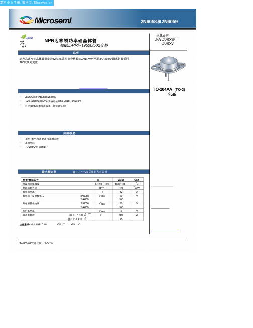
极性:NPN(见
安装硬件:可选绝缘体和金属板螺钉向厂家咨询
重量:约15克
在最后一页.
可靠性水平
JAN = JAN水平 JANTX = JANTX水平 JANTXV = JANTXV水平
空白=商业
JEDEC类 型 号 (see 电气特性
表)
PART命名法
JAN 2N6058 (e3)
符
IB IC IE TC V CB
输出电容
VCB = 10 V,IE = 0,F = 100千赫≤˚F≤1兆赫
2N6058和2N6059
@ T A = +25 Co除非另有说明
符
Min. Max. Unit
2N6058 V(BR)CEO
80
2N6059
100
V
2N6058 2N6059
ICEO
1.0
mA
1.0
2N6058 2N6059
V CBO
V EBO PT
Value -55到+175
1.0 12 80 100 80 100 5 150 75
Unit oC oC/W A V
V
V W
T4-LDS-0307,修订版1(8/5/13)
芯片中文手册,看全文,戳
2N6058和2N6059
机械和包装
案例:行业标准TO-204AD(TO-3),密封,0.040英寸直径引脚. 表面处理:焊接浸锡铅镍镀合金 52或符合RoHS标准雾锡电镀.每MIL-STD-750方法2026焊 性.
集电极电源电压:施加到连接到所述集电极电路电源电压. 集电极 - 发射极电压:集电极和发射极之间直流电压. 集电极 - 发射极电压,基极开路:集电极和发射极端时基极端是开路之间电压.
- 1、下载文档前请自行甄别文档内容的完整性,平台不提供额外的编辑、内容补充、找答案等附加服务。
- 2、"仅部分预览"的文档,不可在线预览部分如存在完整性等问题,可反馈申请退款(可完整预览的文档不适用该条件!)。
- 3、如文档侵犯您的权益,请联系客服反馈,我们会尽快为您处理(人工客服工作时间:9:00-18:30)。
限速低于60公里路段超速50%以下只警告不罚款限速低于60公里路段超速50%以下只警告不罚款公安部出台新交规,当在限速低于60公里路段,机动车超速50%以下时,对驾驶人只警告不处罚。
记者从省公安厅交巡警总队了解到,这是去年底公安部交管局下发的《关于规范查处机动车违反限速规定交通违法行为的指导意见》中的部分内容。
就江苏而言,限速低于60公里的路段包括国、省道和城市道路等,除了危险路段和事故多发路段外,其余的是不测速处罚的。
如果这些路段发生交通事故,经检测机动车超速的,驾驶人还要承担一定责任。
交管新规
四种超速情形通常只警告不处罚
据了解,公安部交管局出台《关于规范查处机动车违反限速规定交通违法行为的指导意见》。
记者注意到,新规明确要求,交警处理违反限速规定的违法行为时,应依法认真调查、比对车友的交通违法证据资料,核查其提供的驾驶证等信息。
对违法证据资料不符合要求的,不得处罚。
对同一辆机动车在同一道路的同一行驶方向,违反限速规定的违法行为处于持续状态,被同一县(市、区)公安交管部门或高速公路交警大队辖区的测速取证设备记录多次的,要选择一次最严重的违反限速规定行为实施处罚。
车友驾驶机动车违反限速规定,属于以下四种情形之一,未造成后果的,由公安交管部门予以警告:
(一)在限速低于60公里小时的公路上超过规定车速50%以下的;
(二)驾驶中型以上客货车、校车、危化品运输车在高速公路、城市快速路以外的道路上超过规定车速10%以下的;
(三)驾驶中型以上客货车、校车、危化品运输车以外的机动车超过规定车速10%以下的;
(四)驾驶机动车在高速公路上行驶低于规定时速20%以下的。
根据这一新规,对于在限速低于60公里的路段超过规定车速50%以下的违法行为,交警只警告,不罚款也不会扣分;超速50%以上,则要被罚款并被记分。
如果某个路段限速达到或超过60公里,一旦车友超速,将按现有超速的相关规定处罚,该罚款的罚款,该记分的记分。
适用范围
部分国、省道和城市大部分道路
据了解,公安部交管局的这个新规定适用范围,包括省内部分限速较低的高速公路匝道、国省道,以及目前各市的大部分城区道路。
比如在xx市区,不少支路街巷的限速都在40公里以下,一些主次干道、快速路、高架或隧道的限速在60公里以下。
如果车友们在这些限速不到60公里的路段发生了超速行为,只要没有超速50%以上,通常只会被警告,不会被罚款或者记分。
如果因超速发生交通事故,车友仍然要承担相应责任。
交警提醒
不罚款不记分仍会被拍摄记录
不少车友认为,现在城市尤其是xx区很多道路限速不到60公里,但这些地方路况非常好,稍不留神就开到七八十公里,如果稍有超速就罚款记分,操作起来有些机械。
公安部交管局出台这一新规,对限速低于60公里的路段超速50%以下的只警告不罚款不记分,体现了执法的人性化。
江苏交巡警则提醒车友,虽然新规对这类超速行为有点“包容”,但并不意味着鼓励超速。
再说,这些情形同样属于交通违法行为,仍会将被电子警察抓拍记录,只是处罚上有所调整。
如果因为超速造成事故,车友仍要承担责任。
所以,为了自己和他人安全,切勿超速。
关键词搜索:温馨提示您还可以返回温馨提示语栏目浏览更多相关范文。
(201X年2月4日
附送:
院学生会201X
院学生会201X
随着假期的临近,201X-201X学年度第二学期学院的各项工作又将接近尾声,安顺学院学生会的工作也将暂时告一段落.回顾本学期乃至本学年度以来院学生会的各项工作,我们毋庸置疑,这个过程中有苦有甜,有得有失,有优点也有不足,有困难也有进步.但是,无论怎么样,总的来说,我们的工作开展得比较正常,而且十分顺利,不管是在与学院十个系的工作交流,与学院个组织间的通力合作,还是就学生会内部各部
门之间的协作配合,都较过去有了很大的提升.另外,在共青团安顺学院委员会的领导及老师的指导下,我们不仅顺利开展了各种大型的校园文化活动,而且在活动圆满结束后,我们会召集院学生会各部部长及主席团成员,在团委指导老师的主持下,分析活动举办过程中出现的纰漏和
不足,大家在会议上各抒己见,总结出经验教训,以便在以后的类似的活动中引以为戒,同时有可借鉴之处.如此这般,使得我们的工作取得了突破性的进展,我们的工作思路和工作方法也更加的成熟.现就安顺院学
生联合会201X-201X学年度第二学期的工作做如下回顾总结:首先,关
于院学生会08级干事的问题.就本学期的工作表现来看,08级干事表现积极,成长得很快,他们在各种活动中充分发挥了自身的主观能动性,懂得该为可为而为之,我相信这也是我们的工作取得较大脑筋部的原因之一.其次,关于"青春动力"系列品牌活动的举办问题.四月中旬,由中国
电信XX分司,共青团安顺学院委员会主办,院学生会承办的第四届校园"三vs三"篮球赛及第三届"篮球宝贝"评比赛取得了圆满成功.本次活动,不管是队伍的组建数量还是现场的布置,比赛的过和氛围,却较往年有了明显进步.特别是我院的篮球宝贝队伍.就我院目前的现状来说,以前没有组建过篮球宝贝队伍,但现在能在规定期限内组建了十多支篮球宝贝,可以说是难能可贵.第三,关于百事可乐公司助举办的"百事音乐节"活动.5月8日-5月10日,院学生会成功举行了"百事音乐节"的安
顺赛区海选和决赛活动,我院涂鑫同学凭借第一名的成绩,代表安顺赛
区赴贵阳参加总决赛.本次活动不仅极大地丰富了大学生校园文化活动,而且还发掘了一批优秀的音乐人才.第四.关于我院"社团文化展示"活动.5月中旬,我院20多个社团共同举办了关于大学生社团文化展示的活动,前所未有地展示了各个社团的风采,得到了学院广大师生的一致
好评.另外,我院的学生社团正在不断的发展壮大,近期又新成立了吉他爱好者协会,羽毛球协会和心理健康协会三个社团,由此,我院的大学生社团文化的发展壮大可见一斑.第五.关于学术性活动.5,6月份院学生会成功举办了两场学术性的活动---"XX省大生挑战杯"和"大学生英语四级考试讲座".这些活动一方面为我院师生的学术展示提供了个高质的大平台,一方面也为我院广大学生的学习提供了很好的文化辅导和"充电".第六.关于卫生问题.学期初期,在劳生部的协调监督下,组织各系党员及院学生会全体成员进行了一次学院卫生大清扫活动,取得了预想的效果,这次活动极大地促进了广大学生的卫生观念,为我院创设优美清洁的校园环境做出了很大贡献.第七.为了繁荣学院的文艺活动文化.经院团委的批准,组织成立了学院舞蹈队等等.以上就是院学生会本学期进行的活动概况,尽管我们的工作比过去有了较大的进步,但是,在长期的工作当中,也出现了一些缺点和不足,主要表现在一下几方面:一是院学生会各部与院团委的指导老师之间的交流有待进一步提高;二是学生会办公室的基础设施损失严重,比如办公桌的损坏,大扫工具的丢失等,大家爱护公物的观念有待加强;三是学生会的经费短缺,上报学院的日常工作用品,如红纸,墨汁,浆糊,信纸等不能按时实现,给我们的工作带来了极大的不便;四是个别部门的考勤有待加强,缺乏纪律性等.如上所诉,就是院学生会201X-201X学年度第二学期的工作总结情况,尽管我们在学期工作中有得有失,有喜有忧,但是我相信,我们在工作上出现的任何纰漏和不足,却是暂时性的.我们有必要相信,在不断吸取工作上的经验教训之后,我们一定会得到很好的改正.事物都是不断向前发展壮大的,所以院学生会的工作机制也必将会日趋完善.昨天已成过去,昨天终是历史.只要我们团结协作,再接再厉,不断地开拓进取,即便目
标还很遥远,但是希望和未来却捏在我们的手心里.因此,我们相信,院学生会的工作,明天必将更上一层楼!。