第二讲:Lattice公司的isp1016芯片资料
ISP技术
ISP技术 ISP技术
ABEL-HDL语言 编程软件ispEXPERT
ISP技术
ISP技术
ISP技术的特点 ISP逻辑器件系列 ispLSI器件的结构 在系统编程原理和方法
ISP技术的特点
一、在系统编程
在系统编程(ISP):指用户具有在自己设计的线路板上为 重构逻辑而对逻辑器件进行反复编程改写的能力。 ISP技术是美国Lattice半导体公司首先提出来的一种能 在产品设计、制造过程中的每个环节具有对其器件、电路或 整个数字系统的逻辑和功能随时进行组态或重组能力的最新 技术。在可编程逻辑器件(Programming Logic Device, PLD)及其技术中,ISP是一种新的概念、新的标准。
ISP逻辑器件系列
目前,商品化的在系统可编程逻辑器件有 (1)ISPLSI (2)ISPGAL (3)ISPGDS(Generic Digital Switch).
ISP逻辑器件系列
一、ispLSI系列
美国Lattice公司是世界上第一片GAL诞生地.特别是九十年 代发明并率先推出的ISP技术,开拓了新一代的ttice公 司已将ISP技术应用到高密度可编程逻辑器件(HDPLD)中,形 成ispLSI系列高密度在系统可编程逻辑器件.
可变成逻辑器件厂商
随着可编程逻辑器件应用的赢利吸力和日益广泛,许多IC制 造厂家涉足PLD/FPGA领域。目前世界上有十几家生产 CPLD/FPGA的公司,最大的三家是:ALTERA,XILINX, Lattice,其中ALTERA和XILINX占有了60%以上的市场份额。 3、 Lattice:Lattice是ISP技术的发明者, ISP技术极大的 促进了PLD产品的发展,与ALTERA和XILINX相比,其开发 工具比ALTERA和XILINX略逊一筹。中小规模PLD比较有特 色,不过其大规模PLD、FPGA的竞争力还不够强 1999年 推出可编程模拟器件。99年收购Vantis(原AMD子公司), 成为第三大可编程逻辑器件供应商。2001年12月收购agere 公司(原Lucent微电子部)的FPGA部门。主要产品有 ispLSI2000/5000/8000, MACH4/5,ispMACH4000等
isplsi1016-mil CPLD

figure 1). The outputs of the eight GLBs are connected to GLBs and I/O cells. The Clock Distribution Network can
a set of 16 universal I/O cells by the ORP. The ispLSI also be driven from a special clock GLB (B0 on the ispLSI
— tpd = 20 ns Propagation Delay
B P — TTL Compatible Inputs and Outputs
— Electrically Erasable and Reprogrammable — Non-Volatile E2CMOS Technology — 100% Tested
ispLSI® 1016/883
In-System Programmable High Density PLD
Features
Functional Block Diagram
• HIGH-DENSITY PROGRAMMABLE LOGIC
— High-Speed Global Interconnect — 2000 PLD Gates — 32 I/O Pins, Four Dedicated Inputs
H U 1 • COMBINES EASE OF USE AND THE FAST SYSTEM - SPEED OF PLDs WITH THE DENSITY AND FLEX-
IBILITY OF FIELD PROGRAMMABLE GATE ARRAYS
E IN — Complete Programmable Device Can Combine Glue A Logic and Structured Designs
飞思卡尔芯片简介

• RS08微控制器—S08內核的簡化版, 在某些應用領域更有效,更便宜。 例如簡單的電子機械設備遷移到固態 控制。 • S08微控制器—從通用HC08微控制器 轉化而來。總線速度更快,操作電壓 更低,S08更適用于電池供電的應用。 • ColdFire嵌入式控制器—可兼容,
微處理器
歡迎來到飛思卡爾獨家 推出的微控制器集
/contiuum
/continuum
飛思卡爾公司 的優勢
飛思卡爾公司是嵌入式控制領域的全球 帶頭人,是MCU技術的先驅,並是主要 技術創新者。我們開發了首個基于flash 存儲的MCU。微控制器集提供了接觸我 們市場主導產品的簡單方法。全套的工 具、培訓和支持,包括常規開發工具、 參考設計、應用筆記和網上直播。使得 你的設計更快捷。
關于微控制器集
飛思卡爾公司的微控制器集是業界首個也是唯一一個8位到32位兼容產品的路線圖。從入門 級的RS08和S08控制器到全特征的ColdFire產品,微控制器集使用相同的外圍模塊和開發工 具,簡化了設計過程並縮短推向市場的時間。逐步兼容即可將微控制器集內的設備從低端 到高端遷移到下一個兼容的設備上。例如:將MC9S08JM60 (JM60)遷移到MCF51JM128 (JM128)上,然後只要花少量時間和精力就可遷移到MCF5221x MCUs。 在優化產品性能,價格和功能時,您可能會產生從8位轉到32位的需求,反之亦然。您只要簡 單地更換板上的控制器,重新編譯代碼。微控制器集的8位和32位的連接點是我們的FlexisTM 系列微控制器。
8 KB SRAM
MCF51JM128:
• 50.33MHz V1 ColdFire 內核 • 25.17MHz總線頻率 • 2.7-5.5V的操作電壓 • 80引腳LQFP,64引腳LQFP, 64引腳QFP,44 引腳LQFP封裝
采用ispLSI1016芯片设计数控系统的位置板
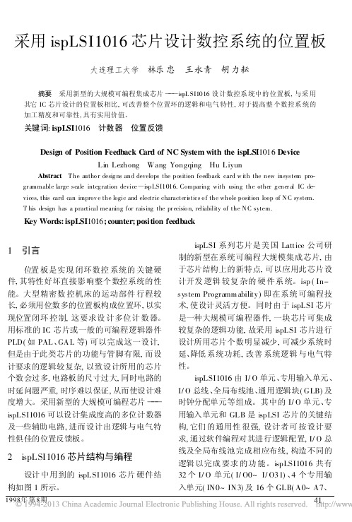
采用ispLSI1016芯片设计数控系统的位置板大连理工大学林乐忠王永青胡力耘摘要采用新型的大规模可编程集成芯片)))ispL SI1016设计数控系统中的位置板,与采用其它IC芯片设计的位置板相比,可改善整个位置环的逻辑和电气特性,对于提高整个数控系统的加工精度和可靠性,具有实用价值。
关键词:ispLSI1016计数器位置反馈Design of Position Feedback C ard of NC System with the ispLSI1016DeviceLin Lezhong Wang Yongqing Hu LiyunAbstract T he autho r desig ns and develops the position feedback card w ith the new insystem pro-gr ammable large scale integ ration device)paring with using the other g ener al IC de-vices,this card can improv e the logic and electr ic character i stics o f the whole position loop of N C system.T his design has a practical meaning for raising the pr ecisio n,reliability of the N C sytem.Key Words:ispLSI1016;counter;position feedback1引言位置板是实现闭环数控系统的关键硬件,其特性好坏直接影响整个数控系统的性能。
大型精密数控机床的运动部件行程较长,必须用位数多的位置板构成位置环,以实现位置闭环控制,这要求设计多位计数器。
用标准的IC芯片或一般的可编程逻辑器件PLD(如PAL、GAL等)可以完成这一设计,但是由于此类芯片的功能与管脚有限,而设计要求的逻辑较复杂,以致设计所用的芯片个数会过多,电路板的尺寸过大,同时电路的时延问题严重,时序难以保证,从而使设计难度增大。
元器件基本知识

---------------------元器件的分类:semiconductor, electronic components, integrated circuits (IC), passive components, active components, connectors, resistors, capacitors, diodes, transistors, switches, sockets一般分主动和被动元器件。
主动类的主要是指集成电路,就是我们说的IC或芯片;被动类的指接插件、电阻、电容、二极管、三极管、开关、插座等。
我们的业务多集中在主动类(体积小、价值大),兼做被动类(体积大、价值一般小,但也有很贵的)。
-------------------元器件厂家:brand, manufacturer全球有5000家以上行业认可的元器件生产厂家,生产的元器件有百万种之多,而且不断的推陈出新,用新产品来替代老产品。
元器件行业是现代工业的基础。
所有的电子产品都需要元器件来做成成品。
好比是建筑业,建筑公司就是我们现在说的OEM (original equipment manufacturer)。
他们采购不同的建筑材料(对我们就是元器件)来做房子(对我们就是电子产品和设备)。
众多的厂家生产的产品,其实独一无二的很少(哪怕是Intel生产的CPU,其他也有生产的,比如AMD、TI和Cyrix),某一厂家生产的大多数产品都有其他的厂家能生产,只不过在具体的性能指标上有这样那样的不同,很多是可以互相替换的。
缩写:MOT: Motorola 摩托罗拉TI: Texas Instrument 德州仪器NS: National Semiconductor美国国家半导体公司Int: IntelAMD: Advanced Micro DevicesAD: Analog Devices美国模拟器件公司Ray: Raytheon美国雷神公司BB: Burr-BrownHar: Harris哈里斯公司Sie: Siemens西门子LT: Linear Tech 凌力尔特公司Level1: Level OneTosh: Toshiba东芝Sam: Samsung 三星CY: Cypress 美国CYPRESS半导体公司Fuji: Fujitsu日本富士通公司GS: General Semiconductor美国通用仪器公司半导体公司GI: General InstrumentHP: Hewlett-Packard 惠普Hit: Hitachi 日立Lat: Lattice莱迪斯半导体公司TI: Texas Instrument德州PH: PhilipsST: SGS-Thomson Microelectronics汤姆逊电子集团---------------------型号的含义:part#, part number, pin number所有元器件都通过型号来标识。
Lattice isplever设计指南及常见问题解答
Lattice ispMACH TM 4000V/B/C/Z 设计指南及常见问题解答目录1介绍 (4)1.1特征 (4)1.2产品系列和器件选择手册 (4)1.3性能分析 (5)1.3.1超快性能 (5)1.3.2最低功耗 (6)2体系结构概述 (7)2.1ISP MACH4000体系结构 (7)2.2结构特征 (9)2.2.1逻辑分配器和3种速度路径 (9)2.2.2带可编程延时的输入寄存器 (10)2.2.3灵活的时钟和时钟使能 (10)2.2.4初始化控制 (11)2.2.5ORP BYPASS多路复用器 (11)2.2.6I/O 单元 (12)2.2.7OE 控制 (12)3设计实现 (13)3.1全局约束 (13)3.1.1Fitter 选项 (13)3.1.2利用率选项 (14)3.2约束编辑器 (15)3.2.1设备设置表 (15)3.2.2封装察看/引脚编辑规划 (15)3.2.3引脚/节点位置分配 (16)3.2.4组分配 (16)3.2.5I/O类型设置 (16)3.2.6资源预留 (17)3.2.7缺省设置 (17)3.3资源约束 (17)3.3.1使用源约束注意事项 (17)3.3.2源约束语法 (18)3.4优化设计方法 (21)3.4.1ispLEVEL 约束选项控制 (21)3.4.2HDL 源文件约束控制 (22)4器件应用要点 (22)4.14K系列器件VCC和VCCO的作用和连接 (22)4.24K系列器件各电源上电时间及要求 (22)4.34K系列器件的全局复位 (22)4.4关于4K系列器件时钟的用法 (22)4.5全局输出使能信号 (23)4.6CPLD的I/O口作为双向口使用时应注意的问题 (23)4.7关于设计中使用宽多路复用器的问题 (24)4.8未使用引脚的处理 (25)4.9I/O5V兼容问题 (25)4.10I/O口的电平设置 (25)4.114K系列器件引脚上、下拉电阻,OD,慢摆率特性的设定 (25)4.12关于引脚的缺省值和更改 (27)4.134K系列器件功耗的计算 (27)4.144K系列器件节点温度的计算 (27)4.154K器件的热插拔 (28)4.16ISP JTAG编程/测试信号 (28)4.17CPU加载的频率 (28)4.184K系列器件可承受的加载次数 (28)4.19加载过程中I/O口的状态 (28)4.20综合工具的选择 (29)4.21关于约束文件 (29)4.22用嵌入的M ODEL S IM 仿真 (29)4.23M ODEL S IM应用点滴 (30)4.244K器件上电电压阀值 (30)4.25ISP LEVER中的版本控制功能 (31)4.26ISP LEVER中C ONSTRAINT E DITOR的G LOBAL C ONSTRAINTS设置 (32)4.27ISP LEVER中的时序分析 (33)5ISPLEVER优化参数快速指南 (33)5.1ISP LEVER常用约束优化参数的含义与推荐设置 (33)5.2ISP LEVER推荐的优化参数设置 (35)6ISPLEVER安装说明 (36)6.1ISP LEVER安装说明 (36)6.2ISP VM S YSTEM安装说明 (37)7相关资料 (37)1介绍ispMACH4000 器件包括3.3V、2.5V和1.8V三个系列。
ispLSI1016

D ’;
C u t = [ m7 C 』 o nM C mO ;
EQ乙AT1 0NS
whe un M = = 0 t e n Co t h n
{o n M. =[ m7 R ]OuM =! t } C u t d R m0 ; t d OuM;
e eC u t l o n M d=C u t . s o n M d一 1 : C u t .l o n M ck=c k; l 0u M . l t ck= ck l: 图 2 分 频 器
维普资讯
第 2 5卷
第 2期
李 太 全等 : p S 1 1 i L I0 6在数 字锁 相 环 中 的应 用 s
4 5
M 的 i L l0 6的 编 程 如 下 : s S11 p
Cm 7. Cm 9 n d it pe oe sy Rm 7 . Rm 0 n d it p oe sy e Ou M t n d it pe oe sy ‘e D ’; rg ‘ e D ’ rg ; ‘e rg
维普资讯
第2 5卷
第 2期
荆 州 师范 学 院学 报 ( 自然 科 学 版 )
J un l f ig h u Tec esC l g ( t rlS in e o r a o n z o ah r ol e Naua ce c ) J e
Q1 Q2 NQ1, , , NQ2, UP, DN pn; i
R= Ou M : t V =O uN ; t
E0UATI oNS
NQ2 DN & 0 & Q & !up =( 2 1 ) # ( ) ( 2 0 # !V & 0 & Q1 l 2 & R)
# ( !V & Q2 & Q1& !UP) # ( DN & Q2 & Q1& ! R) f ; NQ1=( )# ( Q1 !V & Q2 & Q1& !R)
Lattice ispDOWNLOAD Cables 用户指南说明书

HW-USBN-2AispDOWNLOAD CablesUser’s GuideispDOWNLOAD CablesFeatures•Support for all Lattice programmable products–1.2V to 5V programming–Ideal for design prototyping and debugging•Connect to multiple PC interfaces–USB (v.1.0, v.2.0)–PC Parallel Port•Easy-to-use programming connectors•Versatile flywire, 2 x 5 (.100”) or 1 x 8 (.100”) connectors• 6 feet (2 meters) or more of programming cable length (PC to DUT)•Lead-free/RoHS compliant constructionFigure 1. USB Cable – HW-USBN-2A (Parallel Cable - HW-DLN-3C Not Shown)ispDOWNLOAD CablesLattice ispDOWNLOAD® Cable products are the hardware connection for in-system programming of all Lattice devices. After completion of the logic design and creation of a programming file with the Lattice Diamond®, isp-LEVER® Classic or PAC-Designer® software, the Lattice Diamond Programmer, or Lattice's ispVM™ System soft-ware is used to control the programming of devices directly on the PC board. No additional components are required to program a device.After you complete your logic design and create a programming file with the Lattice Diamond/ispLEVER develop-ment tools, you can use ispVM™ System software or Diamond Programmer to program devices on your board. The ispVM System/Diamond Programmer software automatically generates the appropriate programming com-mands, programming addresses and programming data based on information stored in the programming file and parameters you set in ispVM/Diamond Programmer. Programming signals are then generated from the USB or par-allel port of a PC and directed through the ispDOWNLOAD Cable to the device. No additional components are required for programming.ispVM System/Diamond Programmer software is included with all Lattice design tool products and is available for download from the Lattice web site at .ispDOWNLOAD CablesispDOWNLOAD Cable Pin DefinitionsThe functions provided by the ispDOWNLOAD cables correspond with available functions on Lattice programmable devices. Since some devices contain different programming features, the specific functions provided by the isp-DOWNLOAD cable may depend on the selected target device. ispVM System/Diamond Programmer software will automatically generate the appropriate functions based on the selected device. See Table 1 for an overview of the ispDOWNLOAD cable functions.Table 1. ispDOWNLOAD Cable Pin DefinitionsispDOWNLOAD Cable Pin NameispDOWNLOAD CablePin TypeDescriptionVCCProgramming VoltageInputConnect to V CC or V CCJ plane of the target device. T ypical I CC = 10mA. Y our board design supplies the power for V CC . Note: This may not be the same as a target device’s V CCO plane.SDO/TDO Test Data Output Input Used to shift data out via the IEEE1149.1 (JT AG) programming standard.SDI/TDI Test Data Input Output Used to shift data in via the IEEE1149.1 programming standard.ispEN/Enable/ PROG Enable Output Enable device to be programmed.TRST Test Reset Output Optional IEEE 1149.1 state machine reset. DONE DONEInput DONE indicates status of configuration MODE/TMS Test Mode Select Input Output Used to control the IEEE1149.1 state machine.GND GroundInput Connect to ground plane of the target device SCLK/TCK Test Clock Input Output Used to clock the IEEE1149.1 state machineINITInitializeInputIndicates that ORCA ® device is ready for configuration.Figure 2. ispDOWNLOAD Cable In-System Programming Interface for the PC (HW-USB-1A or HW-USB-2A)11. Lattice PAC-Designer ® software does not support programming with USB cables. T o program ispPAC devices with these cables, use the ispVM System software/Diamond Programmer.Figure 3. ispDOWNLOAD Cable In-System Programming Interface for the PC (HW-DLN-3C and Equivalents)11.HW7265-DL3, HW7265-DL3A, HW-DL-3B, HW-DL-3C and HW-DLN-3C are functionally equivalent products.ispDOWNLOAD Cables Figure 3. ispDOWNLOAD Cable In-System Programming Interface for the PC (pDS4102-DL2 or pDS4102-DL2A)Figure 4. Figure 4. ispDOWNLOAD Cable In-System Programming Interface for the PC (HW7265-DL2 or HW7265-DL2A)1.For reference purposes, the 2x10 connector on the HW7265-DL2 or HW7265-DL2A is equivalent to Tyco 102387-1. This will interface tostandard 100-mil spacing 2x5 headers, or a 2x5 keyed, recessed male connector such as the 3M N2510-5002RB. Programming SoftwareispVM System/Diamond Programmer is the preferred programming management software tool for all Lattice devices and download cables. The latest version of ispVM System software or the Lattice Diamond Program-mer is available for download from the Lattice web site at /software.Target Board Design ConsiderationsA 4.7K pull-down resistor is recommended on the TCK connection of the target board. This pull-down is recom-mended to avoid inadvertent clocking of the TAP controller induced by fast clock edges or as V CC ramps up. This pull-down is recommended for all Lattice programmable families.For Lattice device families that feature low power, it is recommended to add a 500 ohm resistor between V CCJ and GND during the programming interval when a USB ispDOWNLOAD cable is connected to a very low power board design. A FAQ is available that discusses this in more depth at:/support/faqs/details.cfm?id=2205The JTAG programming port speed may need to be governed when using the ispDOWNLOAD cables connected to customer PCBs. This is especially important when there is long PCB routing or with many daisy-chained devices. The Lattice programming software can adjust the timing of TCK applied to the JTAG programming port from the cable. This low-precision port setting of TCK depends on many factors, including the PC speed and the type of cable used (parallel port, USB or USB2). This software feature provides an option to slow the TCK for debug or noisy environments. A FAQ is available that discusses this in more depth at:/support/faqs/details.cfm?id=974The USB Download Cable can be used to program Power Manager or ispClock products with Lattice programming software. When using the USB cable with the Power Manager I devices, (POWR604, POWR1208, POWR1208P1), you must slow do TCK by a factor of 2. A FAQ is available that discusses this in more depth at:/support/faqs/details.cfm?id=306ispDOWNLOAD CablesProgramming Flywire and Connection ReferenceRefer to T able 2 when connecting a flywire download cable to systems that use the 1x8-position or 2x5-position connectors. For newer Lattice FPGA families, a 1x10 connector used in conjunction with the ispDOWNLOAD USB cable adds support for the DONE and INITN signals. Both of these signals are inputs to the cable, and can be used to help verify device configuration.Table 2. Flywire Conversion ReferenceFunction FlywireCableWireLabel1x10Connector1x8Connector2x5ConnectorV CC1Red VCC116TDO/SO/SPI_SO Brown TDO227TDI/SI/SPI_SI Orange TDI335ispEN2/Enable/PROGRAMN/SN/SPI_SS_B Y ellow ispEN/PROG4410TRST3/CRESET_B Green TRST/DONE559TMS/MODE Purple TMS663GND Black GND77 4 (2 and 8) TCK4/SCLK/CCLK/SPI_SCK White TCK881DONE3Green TRST/DONE9INITN/CDONE Blue INITN101. For devices that have a V CCJ pin, the V CCJ must be connected to the cable’s V CC, and a 0.1µF decoupling capacitor is required on V CCJclose to the device. Please refer to the device data sheet to determine if the device has a V CCJ pin.2. For older Lattice ISP devices, a 0.01µF decoupling capacitor is required on ispEN/ENABLE of the target board.3. The TRST and DONE pin is multiplexed on the ispDOWNLOAD USB cable. If the device TRST signal is available on the board, connect theUSB flywire TRST/DONE wire to TRST. If the device DONE signal is available on the board (or if both TRST and DONE are available), con-nect the USB flywire TRST/DONE wire to DONE. Please make sure the correct setting is selected in ispVM/Diamond Programmer (Options, Cable and I/O Port Setup). This will tell ispVM/Diamond Programmer whether the TRST/DONE cable is used as a TRST or a DONE signal.4. A 4.7K pull-down resister is recommended on TCK of the target board.Table 3 lists the recommend pin connections. Please contact Lattice technical support for information on unlisted devicefamilies.(e-mail:***************************,phone:1-800-LATTICE).Table 3. Recommended Pin ConnectionsDevice Family TDI TDO TMS TCK ispEN/PROG1,6TRST2/DONE3,6INITN3,6VCC GND LatticeECP3™Mandatory Mandatory Mandatory Mandatory Optional Optional Optional Mandatory Mandatory LatticeECP2M™/LatticeECP2™Mandatory Mandatory Mandatory Mandatory Optional Optional Optional Mandatory Mandatory LatticeECP™/LatticeEC™Mandatory Mandatory Mandatory Mandatory Optional Optional Optional Mandatory Mandatory LatticeXP2™Mandatory Mandatory Mandatory Mandatory Optional Optional Optional Mandatory Mandatory LatticeXP™Mandatory Mandatory Mandatory Mandatory Optional Optional Optional Mandatory Mandatory LatticeSC™/LatticeSCM™Mandatory Mandatory Mandatory Mandatory Optional Optional Optional Mandatory Mandatory iCE40™Mandatory Mandatory N/A Mandatory Mandatory Recommended Recommended Mandatory Mandatory MachXO2™Mandatory Mandatory Mandatory Mandatory N/A N/A N/A Mandatory Mandatory MachXO™Mandatory Mandatory Mandatory Mandatory N/A N/A N/A Mandatory Mandatory ORCA®/FPSC Mandatory Mandatory Mandatory Mandatory Optional Optional Optional Mandatory Mandatory ispXPGA®Mandatory Mandatory Mandatory Mandatory N/A N/A N/A Mandatory Mandatory ispXPLD™Mandatory Mandatory Mandatory Mandatory N/A N/A N/A Mandatory Mandatory ispMACH® 4000Mandatory Mandatory Mandatory Mandatory N/A N/A N/A Mandatory Mandatory ispMACH/ispLSI® 5000Mandatory Mandatory Mandatory Mandatory N/A N/A N/A Mandatory Mandatory MACH®4A4Mandatory Mandatory Mandatory Mandatory N/A N/A N/A Mandatory Mandatory ispGDX2™Mandatory Mandatory Mandatory Mandatory N/A N/A N/A Mandatory Mandatory ispClock™Mandatory Mandatory Mandatory Mandatory N/A N/A5N/A Mandatory Mandatory Platform Manager™Mandatory Mandatory Mandatory Mandatory N/A Optional5N/A Mandatory Mandatory Power Manager/Power Manager II Mandatory Mandatory Mandatory Mandatory N/A Optional5N/A Mandatory MandatoryispDOWNLOAD CablesTable 3. Recommended Pin Connections (Continued)Device Family TDI TDO TMS TCK ispEN/PROG1,6TRST2/DONE3,6INITN3,6VCC GND ispPAC®Mandatory Mandatory Mandatory Mandatory N/A N/A N/A Mandatory Mandatory1. Refer to the ispDOWNLOAD Cable ispEN Pin section below for detailed information on connecting the ispEN/ENABLE pin.2. Refer to the ispDOWNLOAD Cable TRST Pin section below for detailed information on connecting the TRST pin.3. The DONE and INITN signals are only available on the ispDOWNLOAD USB cable. These signals are inputs to the cable and can be used to help verify deviceconfiguration.4. Please refer to the device data sheet. Not all packages have the ENABLE or TRST pin.5.When using P AC-Designer® software to program ispPAC devices, do not connect this pin.6.When using these connections, be sure to select the correct settings in the Cable and I/O Port Setup dialog in the ispVM System/Diamond Programmer soft-ware.Connecting the ispDOWNLOAD CableThe target board must be un-powered when connecting, disconnecting, or reconnecting the ispDOWNLOAD Cable. Always connect the ispDOWNLOAD Cable’s GND pin (black wire), before connecting any other JTAG pins. Failure to follow these procedures can result in damage to the target programmable device. ispDOWNLOAD Cable TRST PinConnecting the board TRST pin to the cable TRST pin is not recommended. Instead, connect the board TRST pin to Vcc. If the board TRST pin is connected to the cable TRST pin, instruct ispVM/Diamond Programmer to drive the TRST pin high as follows:1.Select the Options menu item.2.Select Cable and I/O Port Setup.3.Check the TRST/Reset Pin Connected checkbox.4.Select the Set High radio button.If the proper option is not selected, the TRST pin will be driven low by ispVM/Diamond Programmer. Consequently, the BSCAN chain will not work because the chain will be locked into RESET state.ispDOWNLOAD Cable ispEN PinThe following pins should be grounded:•BSCAN pin of the 2000VE devices•ENABLE pin of MACH4A3/5-128/64, MACH4A3/5-64/64 and MACH4A3/5-256/128 devices.However, the user has the option of having the BSCAN and ENABLE pins driven by the ispEN pin from the cable. In this case, ispVM/Diamond Programmer must be configured to drive the ispEN pin low as follows:1.Select the Options menu item.2.Select Cable and I/O Port Setup.3.Check the ispEN/BSCAN Pin Connected checkbox.4.Select the Set Low radio button.Feature HW-USBN-2A HW-USB-2A HW-USB-1A HW-DLN-3C HW7265-DL3, HW7265-DL3A,HW-DL-3B,HW-DL-3C HW7265-DL2HW7265-DL2A PDS4102-DL2PDS4102-DL2AUSB X X XPC-Parallel XXXXXX1.2V Support X X 1.8V Support X X X X X X X2.5-5.0V Support X X X X X X X XX2x5 Connector X X X X X XX1x8 Connector X X X X X XXFlywire X XXX XLead-free Construction X X Available for orderXXispDOWNLOAD CablesTable 4. ispDOWNLOAD Cable Feature SummaryEach ispDOWNLOAD Cable ships with two small connectors that help you keep the flywires organized. The follow-ing manufacturer and part number is one possible source for equivalent connectors:•1x8 Connector (e.g. Samtec SSQ-108-02-T -S)•2x5 Connector (e.g. Samtec SSQ-105-02-T -D)The ispDOWNLOAD Cable flywire or headers are intended to connect to standard 100-mil spacing headers (pins spaced 0.100 inch apart). Lattice recommends a header with length of 0.243 inches or 6.17 mm. Though, headers of other lengths may work equally well.Ordering InformationDescriptionOrdering Part Number China RoHS Environment-Friendly Use Period (EFUP)ispDOWNLOAD cable (USB). Contains 6' USB cable, flywire connectors, 8-position (1x8) adapter and 10-position (2x5) adapter, lead-free, RoHS compliant construction.HW-USBN-2AispDOWNLOAD cable (PC only). Contains parallel port adapter, 6' cable, flywire connectors, 8-position (1x8) adapter and 10-position (2x5) adapter, lead-free, RoHS compliant construction.HW-DLN-3CNote: Additional cables are described in this document for legacy purposes only, these cables are no longer produced. The cables currently available for order are fully equivalent replacement items.Technical Support AssistanceHotline:1-800-LATTICE (North America)+1-503-268-8001 (Outside North America)e-mail:***************************Internet:ispDOWNLOAD CablesRevision HistoryDate Version Change Summary——Previous Lattice releases.July 200924.1Added Target Board Design Considerations text section.Added Programming Flywire and Connection Reference section head-ing.October 200924.2Added information related to the physical specifications of the flywireconnectors.November 201124.3Document transferred to user’s guide format.Added Figure USB Cable – HW-USBN-2A.Updated Recommend Cable Connections table for MachXO2 devices.Updated Target Board Design Considerations section.Added Appendix A.February 201224.4Updated document with new corporate logo.October 201224.5Added iCE40 configuration port pin names to the Flywire ConversionReference table.Added iCE40 information to Recommended Cable Connections table.ispDOWNLOAD CablesAppendix A. Troubleshooting the USB Driver InstallationIt is essential that you install the drivers before connecting your PC to the USB cable. If the cable is connected before installing the drivers, Windows will try to install its own drivers that may not work.If you have attempted to connect the PC to the USB cable without first installing the appropriate drivers, or have trouble communicating with the Lattice USB cable after installing the drivers, following the steps below:1.Plug in the Lattice USB cable. Choose Start > Settings > Control Panel > System. In the System Propertiesdialog box, click the Hardware tab and Device Manager button. Under Universal Serial Bus controllers, you should see Lattice USB ISP Programmer. If you do not see this, look for the Unknown Device with the yellow flag.2.Double click on the Unknown Device icon.3.Click Reinstall Driver.4.Select Browse for driver software on your computer.For Lattice EzUSB DriverFor FTDI FTUSB Driver5.Browse to the isptools\ispvmsystem directory for the Lattice EzUSB driver or the isptools\ispvmsystem\Drivers\FTDIUSBDriver directory for the FTDI FTUSB driver. For Diamond installations, browse tolscc/diamond/data/vmdata/drivers. Click Next.6.Select Install this Driver software anyway. The system will update the driver.7.Click Close and finish installing the USB driver. Under Control Panel >System >Device Manager > Univer-sal Serial Bus Controllers should include the following:For the Lattice EzUSB Driver: Lattice USB ISP Programmer device installed.For the FTDI FTUSB Driver: USB Serial Converter A and Converter B devices installed.If you are experiencing problems or need additional information, contact Lattice Technical Support.HW-USBN-2A。
- 1、下载文档前请自行甄别文档内容的完整性,平台不提供额外的编辑、内容补充、找答案等附加服务。
- 2、"仅部分预览"的文档,不可在线预览部分如存在完整性等问题,可反馈申请退款(可完整预览的文档不适用该条件!)。
- 3、如文档侵犯您的权益,请联系客服反馈,我们会尽快为您处理(人工客服工作时间:9:00-18:30)。
• 串行时钟SCLK(Serial Clock);
• 模式选择Mode;
• 整个芯片的使能端ispEN。
当ispEN引脚加高电平时,器件处于正常模式。当 ispEN引脚加低电平时,器件处于编程状态,所有I/O端 的三态缓冲电路皆被禁止而处于高阻状态,从而割断了 芯片与外电路的联系,避免了编程芯片与外电路的互相 影响。
在系统编程接口——串行菊花链方式:
SDO SDI MODE SCLK ispEN
5线ISP编程接口
ispLSI 1016
ispGDS
在系统可编 程数字开关
ispGAL
ispLSI
返回目录
查看ispLSI 1016功能框图
二、isp器件的编程
1. 条件:
PC机、ISP编程电缆、ISP Download软件。
微机
ispDOWNLOA D
Software (Isp下载软件)
ispDOWNLOAD Cable
(Isp下载电缆)
ISP器件 系统电路板
2. 编程接口: • 串行数据输入SDI(Serial Data In);
• 最大工作频率 fmax = 125 MHz。
2. ispLSI 1016的结构框图——引脚图
3. ispLSI 1016的结构框图——功能框图
返 回
1) 集总布线区GRP(Global Routing Pool) 该区位于芯片的中央,其任务是将所有片内
逻辑联系在一起。
2) 万能逻辑块GLB(Generic Logic Block) GLB位于GRP的两边,每边8块,共16块。每
第二讲:Lattice公司的isp1016芯 片
一、ispLSI 1016的结构和特点
ispLSI 1016是ispLSI 1000系列中容量最小的 器件,具备5V的在系统编程能力。
1. ispLSI 1016的主要特点:
• 集成密度为2000等效门;
• 是电擦写CMOS(EECMOS)器件;
• 有44个引脚,其中32个是I/O引脚,4个是专 用输入引脚;
查看ispLSI 1016功能框图
5) 时钟分配网络CDN(Clock Distribution Network)
• CDN的输入信号由三个专用输入端Y0、Y1、Y2提供;
• CDN的输出有五个,其中CLK0、CLK1、CLK2提供给 GLB,IOCLK0和IOCLK1提供给I/O单元;
• 时钟专用GLB(B0)的四个输出送至CDN,输入输出单元IOC(Input Output Cell) 输入输出单元IOC是功能框图最外层的小方
块,共32个(IN0 ~ IN31)。该单元有输入、输 出和双向I/O三类组态。可通过对控制输入输出 三态缓冲器的使能端编程来选择。
查看ispLSI 1016功能框图
4) 输出布线区ORP(Output Routing Pool)
个GLB由与阵列、乘积项共享阵列、四输出逻辑 宏单元和控制逻辑组成。
GLB结构如下图:
查看ispLSI 1016功能框图
GLB结构:
• GLB的与阵列有18个输入端,其中16个来自集 总布线区GRP,2个由I/O单元直通输入。 • 每个GLB有20个与门,形成20个乘积项,再通 过4个或门输出。 • 4输出宏单元有4个触发器,可被组态为组合输 出或寄存器输出(通过编程组态)。
• 例如:将外加主时钟由Y0送入作为全局时钟CLK0,此 全局时钟通过时钟专用GLB(B0)分频后送至CLK1、 CLK2、IOCLK0、IOCLK1,则其它GLB或I/O单元可以工 作在较低的频率上。
查看ispLSI 1016功能框图
6) 大块结构(Megablock)
• ispLSI 1016 采用了一种分块结构,每8个 GLB连同对应的ORP、IOC等构成一个大块。 此 外,每个大块中还包括2个专用输入端,仅供本 大块内的GLB使用,靠软件自动分配。 • ispLSI 1016 共有两个大块。
• 输出布线区ORP是介于GLB和IOC之间的可编程互 连阵列; • ORP的输入是8个GLB的32个输出端; • ORP的输出有16个,分别与该侧的16个IOC相连; • 通过对ORP编程,可以将任一个GLB输出灵活地送 到16个I/O端的任何一个; • 在ORP的旁边还有16条通向GRP的总线,I/O单元可 以使用,GLB的输出也可以通过ORP使用它,从而方便地 实现了I/O端复用的功能和GLB之间的互连。