COT-MV1 开发套件快速入门指南V0.1
LTE-M Expansion Kit 快速入门指南说明书

QSG156: LTE-M Expansion Kit Quick-Start GuideThe LTE-M Expansion Kit is an excellent way to explore and evaluate the Digi XBee3™ LTE-M cellular module which allows you to add low-power long range wireless connectivity to your EFM32/EFR32 embedded application.The Digi XBee3™ LTE-M cellular module is an easy to use cellular module. The LTE-M Expansion Kit easily integrates and brings LTE-M connectivity to compatible Silicon Labs Wireless and MCU Starter Kits through the expansion header.Software examples for the LTE-M Expansion Kit for the EFM32GG11 Giant Gecko STK (SLSTK3701A) are available in Simplicity Studio™. This guide demonstrates how to download and run one of these examples.LTE-M Expansion Kit Contents•Expansion board with Digi XBee3™wireless module socket •Digi XBee3™ LTE-M cellular module •Hologram SIM card •Cellular patch antenna •Quick Start card1. Getting StartedIntroductionThe Digi XBee3™ LTE-M cellular module is capable of sending and receiving SMS messages. This guide will walk through the steps necessary to run the Xbee SMS demo in Simplicity Studio, which demonstrates this capability.Note: An EFM32GG11 Giant Gecko STK (SLSTK3701A) is required for this demo. Please see the following guide for instructions on how to get started with the EFM32GG11 kit:QSG149: EFM32GG11-SLSTK3701A Quick-Start GuideInstall Simplicity StudioSimplicity Studio is a free software suite needed to start developing your application. Download the latest version of Simplicity Studio from the Silicon Labs website:/simplicity-studioActivate the included SIM cardThe included Hologram SIM card must be activated before it can be used with the Digi XBee3™ LTE-M cellular module. This can be done by following these instructions:1.In a browser, navigate to https://hologram.io/ and create a new account.2.Once your account has been activated, navigate to https://dashboard.hologram.io/activate and follow the instructions to completethe activation of your SIM card.Note: The activation process will ask you to configure the SIM's APN to "hologram" with username and password empty. This will be done by automatically by the demo on the EFM32GG11 STK.3.If desired, purchase a phone number for the SIM card on the dashboard in the card's Configuration page. Instructions for this stepcan be found here: https://help.hologram.io/getting-started-with-hologram/how-can-i-get-a-phone-number-to-send-sms-messages-to-my-simNote: Purchasing a phone number is not necessary, as you can still send and receive SMS messages through the Hologram dash-board without one.Assemble the Expansion Board1.Place the Digi XBee3™ LTE-M cellular module into the socket on the expansion board.2.Insert the Hologram SIM card into the SIM card slot on the module.3.Connect the included patch antenna to the module's u.FL connector labeled 'CELL'. The completed assembly is shown in the figurebelow.Download and Run the SMS DemoThe LTE-M Expansion Kit has several demos available for it that run on an EFM32GG11 Giant Gecko STK. To download and run the Xbee SMS demo:1.Once the expansion board is assembled, connect it to the expansion header of an EFM32GG11 STK, as shown below.2.Once the expansion board is connected, the EFM32GG11 STK can then be powered by connecting the USB connector on the leftand setting the switch to the AEM position.unch the demo in Simplicity Studio by finding the [SLSTK3701_lte_xbee_sms] demo under [Getting Started] in the Launcher, under [Demos].4.Follow the initialization sequence on the LCD.Note: The initialization sequence, including finding a cell signal, may take up to one minute. If this process takes longer than a minute, try to find a location with a stronger cell signal.Send and Receive SMS messagesIf you have purchased a phone number for your Hologram SIM card, you may now send SMS messages to this phone number.If you haven't purchased a phone number, you can send SMS messages through the Hologram dashboard instead.The SMS message will be received and displayed on the EFM32GG11 STK's LCD, along with the sender's phone number. The demo will automatically respond back with the message "You are linked to this Xbee" to this phone number. Pressing BTN0 on the EFM32GG11 STK will also send a message stating the number of messages the demo has received so far.Note: Sending and receiving SMS messages may take over a minute.Note: The Hologram SIM card will cause the SMS response from the module to be from a different phone number than the one as-signed to the SIM card. This response will be from a +88 number, and some carriers block these numbers automatically. If you receive no responses from the kit during this demo, you may contact your carrier and request that they allow messages from +88 numbers. Note: The SMS demo will configure the Digi XBee3™ LTE-M cellular module to search for and use the strongest carrier, between Veri-zon and AT&T. The module also has the option to be configured to use a specific carrier, if desired.Additional Resources 2. Additional ResourcesAdditional Software ExamplesTwo additional software examples for the EFM32GG11 Giant Gecko STK are available within Simplicity Studio. These can be accessed from the [Launcher] perspective under [Software Examples] with the kit selected.1.Digi XBee Device Cloud example: This example project uses a Digi XBee module to communicate via LTE-M. It transmits tempera-ture data to the Digi Device Cloud and allows a Cloud user to modify LED's on the board.2.Digi XBee Time Server example: This example project uses a Digi XBee module to receive the current time from an online timerserver and displays the time on the LCD.Additional DocumentationFor more information, please review the following:•UG310: LTE-M Expansion Kit User's Guide•https:///xbee•https://hologram.io/Silicon Laboratories Inc.400 West Cesar Chavez Austin, TX 78701USASimplicity StudioOne-click access to MCU and wireless tools, documentation, software, source code libraries & more. Available for Windows, Mac and Linux!IoT Portfolio /IoTSW/HW/simplicityQuality /qualitySupport and CommunityDisclaimerSilicon Labs intends to provide customers with the latest, accurate, and in-depth documentation of all peripherals and modules available for system and software implementers using or intending to use the Silicon Labs products. Characterization data, available modules and peripherals, memory sizes and memory addresses refer to each specific device, and "Typical" parameters provided can and do vary in different applications. Application examples described herein are for illustrative purposes only. Silicon Labs reserves the right to make changes without further notice and limitation to product information, specifications, and descriptions herein, and does not give warranties as to the accuracy or completeness of the included information. Silicon Labs shall have no liability for the consequences of use of the information supplied herein. This document does not imply or express copyright licenses granted hereunder to design or fabricate any integrated circuits. The products are not designed or authorized to be used within any Life Support System without the specific written consent of Silicon Labs. A "Life Support System" is any product or system intended to support or sustain life and/or health, which, if it fails, can be reasonably expected to result in significant personal injury or death. Silicon Labs products are not designed or authorized for military applications. Silicon Labs products shall under no circumstances be used in weapons of mass destruction including (but not limited to) nuclear, biological or chemical weapons, or missiles capable of delivering such weapons.Trademark InformationSilicon Laboratories Inc.® , Silicon Laboratories®, Silicon Labs®, SiLabs® and the Silicon Labs logo®, Bluegiga®, Bluegiga Logo®, Clockbuilder®, CMEMS®, DSPLL®, EFM®, EFM32®, EFR, Ember®, Energy Micro, Energy Micro logo and combinations thereof, "the world’s most energy friendly microcontrollers", Ember®, EZLink®, EZRadio®, EZRadioPRO®, Gecko®, ISOmodem®, Micrium, Precision32®, ProSLIC®, Simplicity Studio®, SiPHY®, Telegesis, the Telegesis Logo®, USBXpress®, Zentri , Z-Wave, and others are trademarks or registered trademarks of Silicon Labs. ARM, CORTEX, Cortex-M3 and THUMB are trademarks or registered trademarks of ARM Holdings. Keil is a registered trademark of ARM Limited. All other products or brand names mentioned herein are trademarks of their respective holders.。
Multi 三轴手持便携相机 稳定器快速入门V1.0说明书

动相机,点击“相机”进入;安装手机拍摄用户,点击“手机”进入) *安装手机使用时也可连接手机蓝牙:进入手机蓝牙设置——搜索蓝牙设备“Smatphone Gimbal”——点击连接,连接成功后稳定器可控制手机原生相机拍照&录像 *【常见问题】手机蓝牙能连上,APP蓝牙连不上? 1.还原(初始化)手机网络设置;2.关闭wifi或断开蓝牙设备“Smar tphone Gimbal"的连接;3.重新连接操作
常见问题(FAQ)
Q: 开机后电机为什么抖动/震动? A: 确认是否把相机装上再开机,稳定器螺丝是否拧紧,开机前是否调平,确认相机是否过轻,电机扭力过大。 解决解决方案:安装好相机再开机;固定螺丝拧紧;开启稳定器前先调平(具体参照第6页调平); 稳定器出厂默认的电机力度较大,在使用重量较轻的相机时,可能会出现震动的情况。通过APP调小电机扭力 (Hohem Gimbal——设置——电机选项)。
13
9.蓝牙连接
10.人脸追踪拍照
11.快门
12.全景环拍
13.移动延时摄影(含追踪录像)
11
APP其他功能 1. 云台参数设置:(可保存个性化的情景参数/应用场景) A.跟随速度设置(可调整航向/俯仰/横滚三轴的跟随速度快/慢) B.摇杆速度设置(调整摇杆控制转动速度快/慢) C.跟随死区区间(死区范围内,稳定器不跟随) D.微调(可对横滚&俯仰轴进行强制性小角度调整,如为达到理想水平状态强制调整角度) E.摇杆控制方向切换(摇杆方向与轴的转动方向一致/相反) F.电机选项:扭力设置(可调整航向/俯仰/横滚三个电机的扭力大小。如手机过轻导致的云
SLAMTEC MAPPER开发板快速使用指南说明书
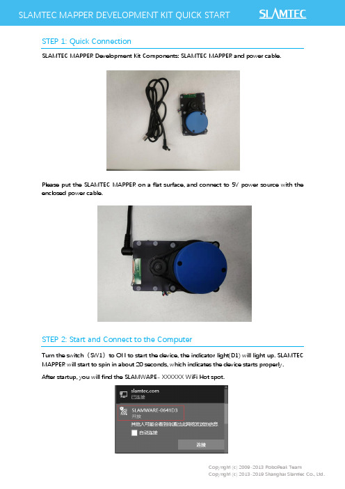
SLAMTEC MAPPER DEVELOPMENT KIT QUICK STARTSTEP 1: Quick ConnectionSLAMTEC MAPPER Development Kit Components: SLAMTEC MAPPER and power cable.Please put the SLAMTEC MAPPER on a flat surface, and connect to 5V power source with the enclosed power cable.STEP 2: Start and Connect to the ComputerTurn the switch(SW1)to ON to start the device, the indicator light(D1) will light up. SLAMTEC MAPPER will start to spin in about 20 seconds, which indicates the device starts properly.After startup, you will find the SLAMWARE- XXXXXX WiFi Hot spot.Please connect to the above SLAMWARE- XXXXXX network (you can also connect SLAMTEC MAPPER to PC via Ethernet cable. Please set the network mode as DHCP client).STEP 3: download the RoboStudioPlease download the Robostudio from our official website:/en/RoboStudioAnd then start the RoboStudio application. Right click at the robots panel and select manual connect. Use 192.168.11.1 for IP address and 1445 for the port (default settings). With a successful connection, the discovered map and real-time laser scan will be shown in the main workspace of the Robostudio.STEP 4: More Reference1.For more details of RoboStudio, please refer to the documents in the RoboStudio documents2.For more usage of SLAMTEC MAPPER Kit, please refer to the SLAMTEC MAPPER User Manual3.For the electrical characteristics and specification of SLAMTEC MAPPER, please refer to theSLAMTEC MAPPER DatasheetYou can download all the above documents from /, more help please contact ******************* .。
TWR-K20D50M 开发板快速入门指南说明书

TWR-K20D50M Quick Start Guide 50 MHz K20 Family of MCUs2Quick Start GuideGet to Know the TWR-K20D50MGeneral-Purpose Tower Plug-InK20 MicroUSBConnectorJM60 BDM JM60 BootloaderEnablePotentiometerMicrophone Power/OSJTAG Mini-AB USB ConnectorSW2 SW3Figure 1: Front side of TWR-K20D50M board (TWRPI devices not shown)SW1 (Reset)Touch TWRPI Socket Enable Options 2LED Green and BLue LED/Touch Buttons JTAG Connector Device Enable Options 1RegulatorOption SelectorBoard Power Selector3TWR-K20D50MFreescale Tower System Development Board PlatformThe TWR-K20D50M board is designed to work either in standalone mode or as part of the Freescale Tower System, a modular development board platform that enables rapid prototyping and tool re-use through reconfigurable hardware. Take your design to the next level and begin constructing your Tower System evaluation board platform today by visiting /Tower for additionalTower System boards and compatible peripherals.Figure 2: Back side of TWR-K20D50M boardBuzzerInfraredPortVBAT (RTC) Battery HolderQuick Start Guide• Tower System developmenttool-compatible board• MK20DX128VLH5 MCU(50 MHz, 128KB Flash, 16 KBRAM, 32 KB FlexNVM, low power, 64LQFP package• Dual-role USB interface with Micro-AB USB connector• Touch Tower Plug-in Socket• General-purpose Tower Plug-in (TWRPI) socket• Onboard debug circuitMC9S08JM60 open source JTAG (OSJTAG) with virtual serial port • Three-axis accelerometer(MMA8451Q)• Four (4) user-controllable LEDs • Two (2) capacitive touchpads• Two (2) user pushbutton switches • Infrared transmit and receive• Potentiometer• Microphone (ADC)• Buzzer• Battery backup for RTCTools• Freescale’s CodeWarrior Development Studio for Microcontrollers v10.1(CW-MCU10)• IAR EWARM V6.30TWR-K20D50M Features42Install Softwareand ToolsInstall the OSBDM/OSJTAG Tower Toolkit to install the OSJTAG and USB-to-Serial drivers.3Configure theHardwareConnect one end of the USB cable to the PC and the other end to the Power/ OSJTAG mini-B connector on the TWR-K20D50M module. Allow the PC to automatically configure the USB drivers if needed.4Press Switches andTouch ElectrodesA tone will beep when SW2 or SW3 are pushed, touch the pads on E1-E2 and LEDs will turn on.5Tilt theBoardSound can be heard through the board buzzer depending on inclination angle.6Clap or Whistle Nearthe Board Microphone Your TWR-K20D50M will respond witha tone.7ExploreFurtherExplore Kinetis 50 MHz devices ultra-low power modes and USB communication by conducting the additional Labs located at /TWR-K20D50M.Step-by-StepInstallation Instructions5Quick Start GuideTWR-K20D50M Jumper OptionsThe following is a list of all the jumper options. The default installed jumper settings are indicated in the shaded boxes.6 TWR-K20D50M Jumper Options (cont.)7Get StartedDownload installation software and documentation underSupportVisit /support for a list of phonenumbers within your region.WarrantyVisit /warranty for completewarranty information.For more information, visit /TowerJoin the online T ower community at Freescale, the Freescale logo, CodeWarrior and Kinetis are trademarksof Freescale Semiconductor, Inc., Reg. U.S. Pat. & Tm. Off. Tower is atrademark of Freescale Semiconductor, Inc. All other product or servicenames are the property of their respective owners. © 2012, 2014 FreescaleSemiconductor, Inc.Doc Number: TWRK20D50MQSG REV 1 Agile Number: 926-27272 REV B。
uArm Swift快速入门指南说明书

Quick-Start GuideV1.0May. 2017⚠This is the quick-start guide for uArm Swift.The quick-start of using uArm Swift Pro will be explained in a separate document.Contents.............................. Safety Instructions3................................ Product Overview4 End-Effectors Installation6......................................... Offline Learning Mode 10 Software: uArm Studio (Win/Mac)11...................................... For Developers17.............................. uArm Community20Safety Instructions1.Please don’t put your hands between the arms when uArm is moving.2.Please use the official power supply for safety reasons.3.Please clear a space for uArm, in case of knocking down anything.Product Overview1.Reference Frame2. Buttons & Indicator Lights3. Extension DescriptionEnd-Effectors Installation1. Suction Cup (Default)Preparation: Suction cup, M3 screws and hex bar wrenchStep 1: Fix the suction cup to the front mounting block with the M3 screws.Step 2: Wiring the limited switch and silicon tubeNote: Before unplugging the wire, press the locker of connector and then unplug it.2. Swift GripperStep 1: Fix the gripper to the front mounting block with 2 screwsStep 2: Plug the wire of gripperNote: Because there is no need to use the silicon tube for suction cup,we could use the velcro to fix the tube with the upper arm.3. Swift Universal HolderStep1 : Fix the universal holder to the front mounting block.Step2: Install the pen to the holder.Offline Learning ModeUse buttons on the base to “teach” uArm by hand.Software: uArm Studio (Win/Mac)1.Download uArm Studio from:/#/en/support/2.Device Connection1)Plug in the power cable.2)Press down the power button.3)Connect uArm to your computer via USB.Once connected, you’ll see the connected status on home page. More info is displayed in “Setting”.3.Teach & Play: Learning ModeWhat is Teach & Play?Teach uArm by hand, and then replay the recording anytime.How?1)Make a recording•Click the “New Recording” button to start “teaching”, OR,•Use the buttons on the base (usage of the buttons is the same as that under “Offline Learning Mode”).2)Save your recording3)Replay the recording in different speed and timesWhat makes “Teach & Play” different from “Offline Learning Mode”?1)No time limit while “teaching” with uArm Studio.2)You may save, export your recordings and import recordings made byothers.3)You may apply your recording in Blockly (visual programminginterface, which is explained up next).4.Blockly: Visual ProgrammingWhat is Blockly?Blockly in uArm Studio is a visual programming interface specially designed for controlling uArm.Getting StartedThree “missions” are prepared to get you through Blockly quickly.Please try them out!What can you do with Blockly?1)Control uArm’s basic movements2)Change events (i.e. how you trigger commands)3)Apply recorded movements4)Dig deeper into programming (functions, variables, etc.)5.Mouse & Keyboard ControlThis section is for real-time controlling with mouse and keyboard.You may use your mouse and keyboard shortcuts at the same time.6.Gesture Control: Leap MotionControl uArm with your hand motion, via Leap Motion, a third-party device for hand tracking.If you want to try it out, you will need:1) a Leap Motion Controller2)Driver for Leap Motion Controller installedStart your real-time control with hand motion:For Developers1. LibraryuArm Swift - Arduino Library* Libraries for Python & ROS users will be released soon.2. Communication Protocol.1) Introduction:•u Arm gCode is an important part of the uArm software.•Based on the standard gCode protocol, we add a new protocol head in front of the gCode so that it can be more easily to use and debug.•What’s more, it is designed to be compatible with the standard gCode. (We offer the code of decode the standard gCode)2) Example:•Sending command from PC“#25 G0 X180 Y0 Z150 F5000”//move to [180,0,150] with the speed 5000mm/min•Reply from uArm “$25 OK”3) Commands(TBD).Command can be divided into two parts:Command with underline: it’s the new added protocol head.•The command from PC starts with ‘#’, while the command from uArm starts with’$’.•And the data following the symbol decided by the PC, and the reply from the uArm should have the same data which indicates it finish the command. (In the example above, PC sends the command with ‘#25’ and uArm replies the command with ’$25’)Command without the underline: it’s the standard gCode.Caution1.There should be blank space between each parameter;2.The letters in the command should be capitalized;GCodeCommand Description Feedback 1.#n is used for the debug, if you don’t want to use it please remove it directly.(For Example: G2202 N0 V90\n)2.‘\n’ is the symbol of line feed.Moving Command (parameters are in underline)#n G0 X100 Y100 Z100 F1000\n Move to XYZ(mm), F is speed(mm/min)$n OK \n or$n E x \n(refer to Err output)#n G2201 S100 R90 H80 F1000\n Polar coordinates, S isstretch(mm), R isrotation(degree),H is height(mm), Fis speed(mm/min)$n OK \n or$n E x \n(refer to Err output)#n G2202 N0 V90\n Move the motor to the position ,N isID of joints(0~3),V is angle(0~180)$n OK \n or$n E x \n(refer to Err output)#n G2204 X10 Y10 Z10 F1000\n Relative displacement$n OK \n or$n E x \n(refer to Err output)#n G2205 S10 R10 H10 F1000\n Polar coordinates for relativedisplacement$n OK \n or$n E x \n(refer to Err output)Setting Command(parameters are in underline) #n M17\n Attach all the joint motors$n OK \n #n M2019\n Detach all the joint motors$n OK \n#n M2120 V0.2\n Set time cycle of feedback, returnCartesian coordinates, V istime(seconds)@3 X154.714 Y194.915 Z10.217\n#n M2200\n Check if uArm is moving$n OK V1\n(1moving,0 stop)#n M2201 N0\n attach motor, Nis ID of joints(0~3)$n OK \n or$n E x \n(refer to Err output) #n M2202 N0\n Detach motor, Nis ID of joints(0~3)$n OK \n or$n E x \n(refer to Err output)#n M2203 N0\n Check if the motor is attached, NisID of joints(0~3)$n OK V1\n(1 attached,0 detached)#n M2210 F1000 T200\n buzzer,F is frequency, Tis time (ms)$n OK \n or$n E x \n(refer to Err output)#n M2211 N0 A200 T1\n Read EEPROM N(0~2,0 is internalEEPROM,1 is USR_E2PROM, 2 isSYS_E2PROM), Ais address, T istype (1 char,2 int,4 float)$n OK V10\n#n M2212 N0 A200 T1 V10\n Write EEPROM N(0~2,0 is internal EEPROM,1 is USR_E2PROM, 2 isSYS_E2PROM), A is address, T istype (1 char,2 int,4 float)V is theinput data$n OK\n#n M2213 V0\n Default function of base buttons (0false, 1 true)$n OK\n#n M2220 X100 Y100 Z100\n Convert coordinates to angle ofjoints$n OK B50 L50 R50\n (Bjoint 0,Ljoint1,R joints 2, 0~180)#n M2221 B0 L50 R50\n Convert angle of joints tocoordinates$n OK X100 Y100 Z100\n#n M2222 X100 Y100 Z100 P0\n Check if it canreach,P1polar,P0Cartesiancoordinates$n OK V1\n (1 reachable,0unreachable)#n M2231 V1\n pump V1working, V0stop$n OK \n or$n E x \n(refer to Err output) #n M2232 V1\n gripper V1close, V0open$n OK \n or$n E x \n(refer to Err output)#n M2234 V1\n Enable/disable Bluetooth(1:enable, 0:disable)$n OK\n#n M2240 N1 V1\n Set the digital IO output$n OK \n or$n E x \n(refer to Err output)M2245 V btname\nSet the name of Bluetooth, 11letters limited (Do not add #n in thiscommand)OK \n Querying Command(parameters are in underline)#n P2200\n Get the current angle of joints$n OK B50 L50 R50\n#n P2201\n Get the device name$n OK V3.2\n#n P2202\n Get the hardware version$n OK V1.2\n#n P2203\n Get the software version$n OK V3.2\n#n P2204\n Get the API version$n OK V3.2\n#n P2205\n Get the UID$n OK V0123456789AB\n #n P2206 N0\n Get the angle of number 0 joint(0~2)$n OK V80\n#n P2220\n Get current coordinates$n OK X100 Y100 Z100\n #n P2221\n Get current polar coordinates$n OK S100 R90 H80\n#n P2231\n Get the status of pump $n OK V1\n (0 stop, 1 working, 2 grabbing things)#n P2232\n Get the status of gripper $n OK V1\n (0 stop, 1 working, 2 grabbing things)#n P2233\n Get the status of limited switch$n OK V1(1 triggered, 0untriggered)#n P2234\n Get the status of powerconnection$n OK V1(1 connected, 0unconnected)#n P2240 N1\n Get the status of digital IO$n OK V1\n (1 High, 0 Low)#n P2241 N1\n Get the status of analog IO $n OK V295\n (return the data of ADC)Ticking (Tip Sensor of Suction Cup) feedback @1Ready@3Time cycle of feedback , ”M2120”@4 N0 V1\n Report the button event.N: 0 = Menu button, 1 = Play buttonV: 1 = Click, 2 = Long Press@5 V1\n Reportevent of power connection@6 N0 V1\n Report event of limit switch in end-effectorErr OutputE20Command not existE21Parameter errorE22Address out of rangeE23Command buffer zone is fullE24Power unconnectedE25Operation failureuArm CommunityUFACTORY Official ForumuArm User Facebook GroupAsk for Help。
MicoKit固件开发手册v1.0.0

MiCO 的关键特性 (1)支持多种网络协议栈,并持续增加中:Bluetooth®low energy,以太网,Wi-Fi,ZigBee, 6LoWPAN; (2)全自动高效功耗管理; (3)支持多种 MCU 体系结构:Cortex-M 系列,MIPS 等,提供 MCU 平台级的抽象化, 标准外设驱动接口; (4)完整的网络安全算法和协议栈,支持常用的传输层安全协议 TLS; (5)方便易用的应用程序框架,使 MiCO 应用安全地直达云端; (6)支持多种 MCU 常用的开发调试环境,可以进行硬件仿真。提供命令行接口和标准调 试信息输出,方便实现运行中的调试; (7)提供完整的设备量产技术,如引导程序,量产烧录,远程网络升级服务,生产测试 程序等; (8)基于 MiCO 系统开发的 IoT 设备软件已经成功地运行在大量的商品上,是一个被证 明了的,安全,稳定,可靠的软件平台。 MICO 详细资料请查看 MICO 开发者网站:http://mico.io/?page_id=31
五、AppFramework
MicoKit 基于 MICO 操作系统,并且集成了 FogCloud 云接入功能,给开发者提供了一 套简单易用的固件应用程序框架,用户只需要修改控制具体硬件模块的代码即可测试相应的 功能,无需关心设备网络连接、云接入、手机 APP 软件界面的修改等工作,大大节约了固 件开发者的开发工作。
MicoKit 固件开发手册
wanges@ 2015.5.15 V1.0.0
MXCHIP
uccnc stepcraft oem package 快速入门指南说明书
Quick Start Guide.04/21ENScope of deliveryIf bought new, the package includes:• USB dongle with software, manualsand sample files• UC 100 Controller • USB cableFor D-Series additionally:• Parallel module• Mainboard cover for the parallel moduleSystem requirements:• Min. 1,6 GHz Processor • 1 GB RAM• 16 GB Hard disk space•Windows XP, 7, 8, 10 (32- or 64-Bit-Version)After selecting your machine type, install UCCNC (Step 1).Then add your license file. (Step 2).Click Next after you have completed both steps.Open the UCCNC application using the shortcut on your computer desktop.InstallationTo begin the installation, open the directory of the USB dongle and execute the file setup.exe . You’ll need administra-tive privileges. It’s best to close all other running applications before continuing with the installation of UCCNC. The installation will guide you through the necessary steps to setup UCCNC for your CNC machine.E NNew functionalitiesDrive to a position incremen- tally. The machine drives to the entered distance withregard to the current position. After clicking one of the buttons you can enter the desired distance to drive.Instantly drive to a predefined position: front left, middle of machine table, back mid-dle. Additionally you can save three of your own positions using the macros M20153,M20154, M20155. To do so,close UCCNC and navigate to the UCCNC profile directory.Open the according macro and edit these lines: double posZ = <Your Value>; double posX = <Your Value>;double posY = <Your Value>;C:\<UCCNC-Installation-directory>\Profiles\Macro_<YourStepcraftModel>Double homing for greater precision. The machine first homes itself quickly, followed by a slower, more precisehoming.Drive to a position using ab-solute coordinates (machine coordinates). After clicking one of the buttons, you can enterthe coordinate.Activate or deactivate the safe-ty enclosure (optional equip-ment) control. If activated, this option works like an additional safety switch that is triggered by opening the enclosure door.Place the spindle (with an inserted end-mill) as pictured. Place and hold a Tool Length Sensor (TLS) to the right side of the 4th axis - align it to the end-mill. Click.UCCNC now performs the horizontal measurement. Make sure the tool can actually trigger the TLS.Now place the TLS onto the machine table, to theright of the 4th axis. Click to perform the second measurement. This will measure the vertical dis-tance. The function then automatically calculates the center of the 4th axis.1.2.Functions designated to find the center of the 4th axis (STEPCRAFT Art.No. 10055). To achieve this, a horizontal and vertical measurement are taken in order to calculate thecenter.1. 2.ENThis function automaticallyfinds the outlines of a work-piece and calculates the cen-Place the 3D-Probe about 5 mm and centered in front ofthe workpiece. After clicking one of the buttons, UCCNCasks for the outer dimensions of the workpiece.After the first measurement a safety distance of 20 mmwill be kept. After performing all measurements, thefound X/Y-dimensions of the workpiece are displayed.The second message box shows the X/Y-coordinate of theworkpieces center.The machine repeatedly movesalong all axes. This can behelpful to spread machinegrease/ oil after maintenance.This function is also helpfulin colder environments (heat-ing up the machine, functiontest). The process takes a fewminutes.This function automaticallyprobes the inner contour of aworkpiece in order to find itscenter. Place the 3D-Probeallows the probe to touch the inner contour.After clicking one of the buttons UCCNC will ask you toenter the inner dimensions of the form. Then the mea-surements are performed. The first message box displaysthe found center coordinates. The second message boxshows the found X/Y-measurements.If you want to find the outlineof any side, manually place theing side of the work piece. Click the according button.The found coordinate is displayed in a message box.To find the coordinates of a corner , place thesure to place the probe 15 mm or lessfrom the edges of the corner.After executing the necessary measure-ments, the 3D-Probe will be placed witha 1 mm offset (in X-, Y- and Z-direction) from the corner.Check the machine coordinates to get the coordinates ofthe corner. Remember the 1 mm offset!You can find a Z-height by using the function. Thefound Z-value is displayed in a message boxFind outlines using a 3D-Probe.The probe is moved accordingto the pictured arrow directionuntil it hits an outline. Click onone of the arrows to trigger ameasurement.max.15E NThis function compensates thedifference in length between a 3D-Probe and an end-mill. The compensation can be applied to reuse a zero-point with an end-mill, which originally wasfound with a 3D-Probe. This allows you to find zero-points in areas a Tool Length Sensor (TLS) cannot reach – like ina slot. Follow these steps:1. Manually zerothe desired Z-position using the3D-Probe. Then move the 3D-Probe out of the way – somewhere over the machine table.2. Click. The first measurement in Z-direction will beperformed. After that the Z-axis will retract upwards.3. UCCNC prompts you to exchange your 3D-Probe for your spindle and desired tool. After exchanging, place a TLS below the tool. Click OK to trigger the secondmeasurement in Z-direction.4. The difference in length will now automatically be compensated. From now on you can navigate to the exact Z-position you zeroed in Step 1.Digitize allows you to probe 3D forms using a 3D-Probe. For more detail see the info video on Youtube:https:///watch?v=yJhWasl8QYwMeasurement along the X-axis.The slant of the workpiece is aligned along the X-axis. Clickand enter X.The 3D-Probe moves as pictured:Measurement along the Y-axis.The slant of the workpiece is aligned along the Y-axis. Clickand enter Y.The 3D-Probe moves as pictured:This function can be used to align the internal coordinate system along a slanted work-surements with a 50 mm spacing in between are taken. To prevent damages, align your workpiece in a way that allows the 3D-Probe to move 50 mm. The Reset Anglebutton resets the coordinate system. There are twopossibilities of applying this function:Now that the angle of the workpieces slant is known, the coordinate system is tilted accordingly. It can be neces-sary to reload your milling program, if the tilt is not visiblein the preview window of UCCNC.Manually change tools. Place your Tool Length Sensor (TLS) under the current tool.After clicking, the current-ly held tool will be measured.Then UCCNC will prompt youto change your tool. After changing it, click OK . The new tool will be measured, too. Afterwards you can continueyour current job by clicking CYCLE START.ENYou can disable the automatic tool changer (ATC) by using this button. When the button is lit up green, the ATC is activat-ed. This does not influence the OFFSETSfunction.1) Tool magazine with integrated TLS:After clickingUCCNCautomatically offsets all tools. Tool 1 always is the first to be measured. Tool 1 will be picked up after the process has beencompleted.2) Tool magazine without integrated TLS:Place your tool changer in about 20 cm distance to the tool magazine. Position a TLS below the spindle. After clickingall toolswill be offset. Tool 1 will be picked up after the pro-cess has been completed.This OFFSETS -function has two possibilities of operation, depending on the used type ofTool Length Sensor (TLS):It is possible to save three indi-vidual parking positions. Use the macros: M200, M201,M202.Clicking performs amanual M6 tool change. UCCNC prompts you for the number of the tool you want to pick up. If you enter 0, you will exit the dialogue.STEPCRAFT accessoriesThe equipment used in this manual can be acquired from the STEPCRAFT shop:https:///3D-ProbeArt.No.: 10024Rotary Table with Three-Jaw Chuck (4. Axis)Art.No.: 10055Tool Length Sensor TS-32Art.No.: 10103You can save five individual macros. Use the macro files:M20210, M20211, M20212,M20213, M20214.ENIn case UCCNC does not find a license and machine profile, it will only offer demo-profiles. The pictured window will be displayed. Check these three points:• Is your controller properly connected to the CNC machine? • Is the USB cable properly connected to the controller and PC?• Is your machine profile saved in the directoryC:\UCCNC\Profiles ?If these three points are positive, continue with the next step.Click Browse and navigate to the directory of your UCCNC instal-lation. According to your operating system you have to choose the applicable directory:64bit C:\<UCCNC Installationsordner>\USB_installer\x6432bit C:\<UCCNC Installationsordner>\USB_installer\x86Confirm your selection by clicking Next and wait for the installa-tion to finish. Start UCCNC to see, if the correct profile is being loaded.In some cases re-installing the controller drivers manually has proven to be helpful. Close UCCNC and open the Windows Device Manager. In this example the UC100 is connected and installed.Right click the controller and choose Update Driver . Select Browse my computer for driver software.Trouble shooting: UCCNC does not load a profiletel.: +49 (0)2373/1791160 mail:************************** net: 。
Two Axis Development Kit 快速入门指南说明书
Two Axis Development KitG e t t i n g S t a rt e d G u i d eT W O A X I S D E V E L O P M E N T K I T Getting Started Guide© Bend Labs1649 W 1700S • Suite 100Salt Lake City, UT 84104T able of ContentsPrecautions (1)Device Setup (2)Expected Output (3)Additional References (4)PrecautionsTwo Axis angular displacement sensor is NOT 5 V tolerant. Requires 1.62 - 3.6 V regulated supply for proper operation.Don’t pull the sensor by the wiresDon’t strain the sensor more than 15%Device Setup1: Connect the Two Axis sensor to the SparkFun Pro nRF52840 Mini via Qwiic Cable Breadboard Jumper and wires as shown below:2: Set up SparkFun Pro nRF52840 Mini in the Arduino IDE o Follow Sparkfun’s guide found at https:///tutorials/nrf52840-development-with-arduino-and-circuitpython to get the nRF52840 Pro Mini up and running inthe Arduino IDE.3: Integrate Sensor and Sparkfun Pro nRF52840 Minio Download example sketches and ads_two_axis Arduino driver at (github link)o Copy two_axis_ads_demo sketch into your Arduino foldero Copy folder ads_two_axis_driver into Arduino/Libraries foldero Connect the nRF52840 Pro Mini to a USB port and reset the Pro Mini into bootloader modeo Select Sparkfun Pro nRF52840 Mini from the Arduino board manager and the associated COM porto Flash two_axis_ads_demo sketch onto trinket M0Expected Output1: Click on tools and then Serial Plotter in the Arduino IDE or CTRL+SHIFT+L to verify that angular data coming from the Two Axis sensor is correct. (Note that touching the sensor while coupled to AC power can cause 60 Hz line noise).2: Click on tools and then Serial Monitor in the Arduino IDE or CTRL+SHIFT+M to interface with the Two Axis Sensor through the serial port. A list of serial commands can be found in the parse_serial_port function in the two_axis_demo sketch.Additional References Pin Diagram:。
Easy-RT1011 快速入门指南说明书
Easy-RT1011快速入门指南基于Easy-RT1011 Re v B UM01010101 1.0.01 Date:2023/3/23类别内容关键词Easy-RT1011摘要介绍Easy-RT1011 Rev B开发板,及其快速入门指南。
修订历史版本日期原因V0.0.90 2019/11/08 创建文档V1.0.00 2019/11/28修订文档格式:1.重新编排第三章例程使用指南;2.修订文中的图片大小和表格格式。
V1.0.01 2023/03/23 更新文档模板目录1. Easy-RT1011开发套件简介 (1)1.1概述 (1)1.1.1i.MX RT1010跨界处理器 (1)1.1.2特性 (1)1.2Easy-RT1011开发套件 (2)1.2.1功能框图 (3)1.2.2板级资源 (3)1.2.3接口说明 (4)2. 资料目录结构说明 (9)3. 例程使用指南 (11)3.1JLINK仿真器 (11)3.1.1概述 (11)3.1.2特点 (11)3.2硬件连接 (11)3.3例程简介 (11)3.4KEIL工程配置选择与编译 (13)3.4.1选择配置标签 (13)3.4.2编译程序 (13)3.5KEIL软件调试 (14)3.5.1工程配置 (14)3.5.2仿真调试 (15)3.5.3调试工具说明 (16)3.6程序下载 (16)4. MCUXpresso IDE使用指南 (18)4.1MCUXpresso IDE简介 (18)4.2SDK的获取及导入 (18)4.2.1获取RT1011的SDK (18)4.2.2向IDE导入RT1011的SDK (20)4.3工程的创建 (21)4.3.1导入模板工程 (21)4.3.2新建工程 (23)4.4调试指南 (24)4.4.1编译工程 (24)4.4.2进入调试界面 (26)4.4.3调试代码说明 (27)4.4.4启动文件配置 (28)4.5固件生成及IDE烧写 (29)4.5.1固件生成 (30)4.5.2IDE烧写固件 (30)4.6IDE使用技巧 (30)4.6.1头文件路径添加 (30)4.6.2代码优化等级的调整 (31)5. 免责声明 (32)1. Easy-RT1011开发套件简介1.1 概述1.1.1 i.MX RT1010跨界处理器i.MX RT1010是NXP半导体公司新推出的一款基于ARM® Cortex®-M7内核的微处理器,继承了i.MX RT系列产品一贯的高性能和易用性。
新唐科技产品生态系统与开发板入门指南说明书
路径 ‒ M031_Series_BSP_CMSIS_Vx.xxxxx
‒ SampleCode ‒ Template ‒ Keil
22
Quick Start – Step 6
项目执行
”Template”专案
打开并执行 1) Rebuild 2) Successfully Compiled 3) Download
(5min)
PinView
(5min)
LV.99
LV.800
Q&A
LV.1
Joe
Joe Howard
Tips
Q&A
SUYU
Quick Start
填问卷抽
Nu-Link2-Pro ($149 USD)
Webinar结束后 系统会自动跳转至问卷页面, 回卷者可抽 Nu-Link2-Pro *1
网络研讨会限定
Programmer
In-circuit Programming (ICP) In-system Programming (ISP) PC control and stand-alone ICP/ISP Automated Programmer header External storage for stand alone ICP/ISP: SD Card, SPI Flash, USB Disk
‐ Arm Keil MDK ‐ IAR EWARM ‐ NuEclipse
板级支持包 (BSP)
‐ Comprehensive drivers ‐ Plentiful peripheral
examples
软件开发工具 –
PinConfigure/ PinView
- 1、下载文档前请自行甄别文档内容的完整性,平台不提供额外的编辑、内容补充、找答案等附加服务。
- 2、"仅部分预览"的文档,不可在线预览部分如存在完整性等问题,可反馈申请退款(可完整预览的文档不适用该条件!)。
- 3、如文档侵犯您的权益,请联系客服反馈,我们会尽快为您处理(人工客服工作时间:9:00-18:30)。
-1-
e、打开“COT-M_SDK_Release_Vx.xx.xx.xx”工程,选择 ST-Link Debugger
-2-
如上,下载成功,说明 STLink 正确安装。
-3-
2.3.
安装下载器驱动 J-Link
a、JLink_Windows_V612c.exe 驱动安装,该驱动供 Jlink 下载器使用。 备注:STLink 或 J-Link 可二选一进行安装。
备注:重要提示请勿将 USB 转串口线红色电源连接到 MV1 转接板电源; 重要提示清勿同时接编程器电源与 USB 转串口电源; 以上二种行为将导致开发板及转接板烧毁;
-5-
3. 联系方式 电子邮箱:support@ 官方网站:
(微信公众号)
-6-
a、软件准备:st-link_v2_usbdriver.exe,JLink_Windows_V612c.exe。 b、安装 st-link_v2_usbdriver.exe 驱动,该驱动供 STLink 下载器使用。 c、STlink 编程器和编程转接板按照标识的线序连接即可。
d、使用转接板下载线将转接板 COT 端与转接板下载座相连,接法如下:
-4-
2.4.
USB 转串口
安装软件开发包提供的“PL2303TA 驱动.zip”驱动。 线序为:红色VCC 5V,黑色GND,绿色TX,白色RX,如下所示,
USB 转串口线 红色线 黑色线(GND) 绿色线(TX) 白色线(RX) COT-MV1 开发底板 VCC GND RXD TXD COT-MV1 转接板 --GND GPIO36(RX) GPIO35(TX)
版权声明: 本手册版权及最终解释权属于 COT,未经我公司书面同意修改本手册将承担法律责任。
目 录
1. 绪论 2. 开发环境搭建 2.1. 安装 IDE 软件 2.2. 安装编程器驱动 STLink 2.3. 安装下载器驱动 J-Link 2.4. USB 转串口 3. 联系方式 -1-1-1-1-4-5-6-
版本历史
日期 版本 变更描述
2017-04-05 2017-07-10
1.00 1.02
初版 调整文档格式
1. 绪论 本文档主要介绍如何快速入门 COT-M1 SDK Develop Kit,将详细阐述 开发环境搭建、COT-M1 开发板使用、例程讲解、相关辅助工具使用等。通 过阅读和学习本文档,用户可快速了解 SDK 开发和开发板使用。若开发者 需要深入理解和学习 SDK,请查阅《COT-M SDK 开发指南.pdf》。 2. 开发环境搭建 2.1. 安装 IDE 软件
a、软件准备:Keil 5.16a,AmbiqMicro.Apollo_DFP.0.9.2.pack b、安装“Keil 5.16a”软件,根据提示默认安装即可。 c、完成步骤 b 后,需导入 AmbiqMicro.Apollo_DFP.0.9.2.pack。 通过以上步骤,IDE 开发环境安装完成。 2.2. 安装编程器驱动 STLink
COT-MV1 开发套件快速入门指南
文档名称 当前版本 初始日期 更新日期 状 态
COT-MV1 开发套件快速入门指南 V1.03 2017-3-17 2017-7-10 发布 COT-MV1 开发套件
文档涉及产品
前 言 使用前请仔细阅读产品规格书。本公司不承担由于用户不正常操作造成 的财产损失或者伤害责任。请用户按照手册中的技术规格和参考设计开发 相应的产品。 本公司有权在任何时候根据技术发展需要对本手册内容进行修改,本公 司不承担修订告知责任。