dynisco高温产品说明书
加德纳丹佛工业用螺铨压缩机油说明书(中文版)讲解

加德纳丹佛工业用螺旋压缩机用油说明书我们推荐使用质量好的、按照下文要求的机油或循环油(液化油)等碳氢化合物润滑剂。
我们主要推荐的是加德纳丹佛 F 2105型螺旋压缩机油,这种机油在压缩机中已经预先填充好。
10升序列号 033 891 41200升序列号 033 891 43如果没有这种油,对油的选择就要注意以下因素:矿物油选用为螺旋压缩机特配的油,此种油中须含有抗氧化剂、抗生锈、防止发泡、抗磨损成分。
合成润滑油选用为螺旋压缩机特配的油,此种油中须含有抗氧化剂、抗生锈、防止发泡、抗磨损成分。
粘性—起始温度最高为500 mm2 /s (﹥0℃)—运行温度最低为7mm2/s (=环境温度的55℃以上)闪点-最低温度为180℃(开杯)在一般环境下,当使用ISO VG 32…46 或 SAE 10W…20W/20 油,这些条件都须满足。
在循环利用油前,必须检查如下的各项(对压缩机的操作有影响):-运行温度(持续在90℃以上的运行温度会使一半的普通油变为矿物油)-耗油量(运行温度越高,耗油量越多)-是否-是否形成漆膜(影响降温和油分离效果)可以通过观察金属棕色漆涂料判断漆膜形成。
注意:不同品质和类型的油不能混合使用第 1 页共14 页目录电子股 (1)控制板.....................................................................................................2. 操作 . (3)主要结构的菜单 (3)读出/状态菜单 (4)错误读出菜单 (4)计时器菜单 (4)操作性设置菜单 (5)调节输出和卸载压力 (5)压力设置计划 (5)调节卸载时间 (6)调节冷凝排水时间 (7)调整电子股置 (8)显示厂家设置菜单 (8)服务菜单 (9)机器配置改编菜单 (10)出厂设置 (11)服务设置 (11)服务诊断菜单 (12)错误警报电气显示 (13)压缩机设置 (15)使用器设置 (15)出厂设置,使用者无法改动 (16)第 2 页共14 页电子股电子股控制着和压缩机调节有关的所有功能。
Dynisco 使用手册

/8 DIN INDICATOR CONCISE PRODUCT MANUAL 59471-2CAUTION: Installation should be only performed by technically competent personnel. Local Regulations regarding electrical installation & safety must be observed. The host equipment is required to provide a suitable electrical, mechanical and fire enclosure to meet relevant safety standards. Impairment of protection will occur if the product is used in a manner not specified by the manufacturer.1Mounting Panel Instrument Housing Ratchets GasketSlide mounting clamp over the instrument housing towards rear face of mounting panel until the tongues engage in ratchets and instrument is clamped in position. Hold instrument firmly in position (apply pressure to bezel only)Note: At first power-up the message is displayed, as described in section 5 of this manual. Access to other menus is denied until configuration mode is completedAlarm 1 Hysteresis* Alarm 2Type High Alarm 2* Low Alarm 2* Al 2 Hysteresis* Output 1 Usage1 LSD to full span in display units on safe side of alarm Options as for alarm 1 Options as for alarm 1 Retransmit PV Output 0 to 10VDC (adjustable) transmitter power supply* 0 to 5 V DC output 0 to 10 V DC output 2 to 10 V DC output 0 to 20 mA DC output 4 to 20 mA DC output Display value between, -1999 & 9999 at Range which Output 1 will be at maximum max Display value between, -1999 & 9999 at Range which Output 1 will be at minimum min Output 1 Power Supply (0 to 10VDC)* Alarm 1, direct, non-latching Alarm 1, reverse, non-latching Alarm 1, direct, latching Alarm 1, reverse, latching Alarm 2, direct, non-latching Alarm 2, reverse, non-latching Alarm 2, direct, latching Alarm 2, reverse, latching Logical Alarm 1 OR 2, direct Logical Alarm 1 OR 2, reverse Any active alarm, direct Any active alarm, reverse As for Output 2 Usage , , , , or (refer to section 6) Reset latched relay(s) Initiate Tare (zero display) Reset min/max PV values Reset Alarm 1 elapsed time Reset Alarm 1 elapsed time & min/max PV values Close contact activates logic state Open contact activates logic state Config Mode lock code, to . Max Min2. SELECT MODESelect mode is used to access the configuration and operation menu functions. It can be accessed at any time by holding down and pressing . The legend is shown for 1 second, followed by the legend for the current mode. Press or to choose the required mode, then press to enter. An unlock code is required to prevent unauthorised entry to Configuration, & Setup modes. Press or to enter the unlock code, then press to proceed. Mode Legendfor 1 sec followed byCAUTION: Do not remove the panel gasket; it is a seal against dust and moisture.Set ValueDescription1. INSTALLATIONInstalling Option Modules/Maintenance 1 /8 Din Size Instruments Rear Terminal WiringAll connections to the device must be made through a spade format or similarDefault Units Unlock Display Codes NoneOutput 1 PV Retransmit Type Retransmit OP 1 Scale maximum Retransmit OP 1 Scale minimum TxPSU 1 levelOperator Set Up Configuration Product InfoNormal operation Tailor settings for application Configure instrument for use Instrument informationCPU PCBMounting StrutsOption Module A Option Module 2connection, with connection to the spade terminal touching both the insulation and conductor material.(Use a standard crimping tool) All connections must be Mechanically secured so as to prevent any wiring becoming loose and coming in contact with other wires or the instrument casing The above applies to any and all connection to hazardous mains supply either direct or indirect (Through a switch (Relay))USE COPPER CONDUCTORS (EXCEPT FOR T/C INPUT)NoneCalibrate Strain Gauge input Calibration Note: Automatic return to Operator Mode after 2 minutes without key activity.3. CONFIGURATION MODEFirst select Configuration mode from Select mode (refer to section 2). Press to scroll through the parameters. While this key is pressed, and up to 1 second after, the parameter legend is shown, followed by the current value. Press or to set the required value. Press to display ? ,press accept the change, otherwise parameter will revert to previous value. To exit from Configuration mode, hold down and press , to return to Select mode. Note: Parameters displayed depends on how instrument has been configured. Refer to user guide (available from your supplier) for further details. Parameters marked * are repeated in Setup Mode. Parameter Legendfor 1 sec followed byOption Module 3Use Screened Cable on Retransmission Option 1Single Strand wire gauge: Max 1.2mm (18SWG)1Option Module 1PSU PCB/8 Din Size InstrumentsOutput 2 UsageSet ValueAdjustment Range & Description Enables or Disables DefaultingDefault Units Value DisplayCAUTION: All power supply connections to the device must be removed when carrying out any form of maintenance. To access modules 1 or A, first detach the PSU and CPU boards from the front by lifting first the upper, and then lower mounting struts. Gently separate the boards. a. Plug the required option modules into the correct connectors, as shown below. b. Locate the module tongues in the corresponding slot on the opposite board. c. Hold the main boards together while relocating back on the mounting struts. d. Replace the instrument by aligning the CPU and PSU boards with their guides in the housing, then slowly push the instrument back into position. Note: Option modules are automatically detected at power up. Mode Defaultof Values within ModeOutput 3 Usage Display StrategyInput Range/Type Code Input Type & RangebC bF CC CF JC JF j.C j.F KC KF k.C K.FB: 100 - 1824 ºC B: 211 - 3315 ºF C: 0 - 2320 ºC C: 32 - 4208 ºF J: –200 - 1200 ºC J: –328 - 2192 ºF J: –128.8 - 537.7 ºC J: –199.9 - 999.9 ºF K: –240 - 1373 ºC K: –400 - 2503 ºF K: –128.8 - 537.7 ºC K: –199.9 - 999.9 ºF L: 0 - 762 ºC L: 32 - 1403 ºF L: 0.0 - 537.7 ºCSee following table for possible codes CodeL.F NC NF rC rF SC SF tC tF t.C t.FInput Type & RangeL: 32.0 - 999.9 ºF N: 0 - 1399 ºC N: 32 - 2551 ºF R: 0 - 1759 ºC R: 32 - 3198 ºF S: 0 - 1762 ºC S: 32 - 3204 ºF T: –240 - 400 ºC T: –400 - 752 ºF T: –128.8 - 400.0 ºC T: –199.9 - 752.0 ºFCode Input Type & RangePtF Pt100: –328 - 1472 ºF Pt.C Pt100: –128.8 - 537.7 ºC Pt.F Pt100: –199.9 - 999.9 ºF0 - 20 mA DC 4 - 20 mA DC 0 - 50 mV DC . 10 - 50 mV DC 0 - 5 V DC 1 - 5 V DC 0 - 10 V DC 2 - 10 V DC -10mV-50mVLogic Input UsageOption Module Connectors 1 /8 Din Size InstrumentsLogic Input State Config Lock4. SETUP MODENote: Configuration must be completed before adjusting Setup parameters. First select Setup mode from Select mode (refer to section 2). Press to scroll through the parameters (while this key is pressed, and for 1 sec after, the parameter legend is shown, then the current value). Press or to change the value. To exit from Setup mode, hold down and press to return to Select mode. Note: Parameters displayed depends on how instrument has been configured. Parameter Legendfor 1 sec followed byOption Slot 2 Connector PL4AOption Slot 1 Connectors PL7 & PL8 Option Slot A Connectors PL5 & PL6PtRh20% vs. 40%: P24C 0 - 1850 ºCLC LF L.CSet ValueAdjustment Range & DescriptionDefault ValueUnits DisplayP24F 32 - 3362 ºF PTCPtRh20% vs 40%: Pt100: –199 - 800 ºCEnables or Disables Defaulting of Mode Default Input Filter Time Constant Alarm Filter time Constant Input fail Mode Process Variable Offset Raw PV value High Alarm 1 Low Alarm 1 Alarm 1 Hysteresis Values within Mode OFF or 0.5 to 100.0 secs OFF or 0.5 to 100.0 secs When input fails PV should go Low or High scale reading ±Span of controller . blank (Alm1only = )Note: Decimal point shown in table indicates temperature resolution of 0.1° Parameter Legendfor 1 sec followed bySet ValueAdjustment Range & DescriptionDefault Units Value Display Max (Lin = 1000) Min (Lin = 0). .Option Slot 3 Connector PL4BPanel-MountingThe mounting panel must be rigid, and may be up to 6.0mm (0.25inch) thick. Cut-out sizes are: Cut-Out Dim A Cut-Out Dim B 1 1 /8 Din = 92mm /8 Din = 45mm For n multiple instruments mounted side-by-side, cut-out A is 96n-4mm (1/8 Din)A BScale Range Upper Limit Scale Range Lower Limit Decimal point position Linear Range Engineering Units Display Multi-Point Scaling Alarm 1Type High Alarm 1* Low Alarm 1*MmScale Range Lower Limit +100 to Range Maximum Range Minimum to Scale Range Upper Limit -100 =XXXX, =XXX.X, =XX.XX, =X.XXX (non-temperature ranges only)This diagram shows all possible option combinations. The actual connections required depend on the model and options fitted. CAUTION: Check information label on housing for correct operating voltage before connecting supply to Power Input Fuse: 90 – 264V ac – 1amp anti-surge 24/48V ac/dc – 315mA anti-surgeNone (Blank), °C or °F Enables or disables the input multi-point scaling feature Process High Alarm Process Low Alarm No alarm Alarm 1 value, adjustable within scaled range, in display units Max Min° °Tolerance +0.5, -0.0mmHigh Alarm 2 Low Alarm 2 Al 2 Hysteresis Scaling Breakpoint 1 Display Value 1Linear input value, un-scaled (mA, mV or VDC) Alarm 1 value, adjustable within scaled Max range, in display units Min 1 LSD to full span in display units on safe side of alarm Max Min Options as for alarm 1 Multi-point scaling breakpoint 1 value, adjustable from to in % of span Range Value to be displayed at multi-point Max scaling breakpoint 1, in display units Multi-point scaling breakpoint 2, adjustable up to 100% of span. Must be > valueElectrical shock can result in death or serious injury. Avoid contact with the leads and terminals. High voltages that may be present on leads can cause electrical shock(Alm1only = )Scaling Breakpoint 2Display Value 2 Scaling Breakpoint 3 Display Value 3 Scaling Breakpoint 4 Display Value 4 Scaling Breakpoint 5 Display Value 5 Scaling Breakpoint 6 Display Value 6 Scaling Breakpoint 7 Display Value 7 Scaling Breakpoint 8 Display Value 8 Scaling Breakpoint 9 Display Value 9 Tare FeatureValue to be displayed at Multi-point scaling breakpoint 2, in display units Multi-point scaling breakpoint 3, adjustable up to 100% of span. Must be > value Value to be displayed at Multi-point scaling breakpoint 3, in display units Multi-point scaling breakpoint 4, adjustable up to 100% of span. Must be > value Value to be displayed at Multi-point scaling breakpoint 4, in display units Multi-point scaling breakpoint 5, adjustable up to 100% of span. Must be > value Value to be displayed at Multi-point scaling breakpoint 5, in display units Multi-point scaling breakpoint 6, adjustable up to 100% of span. Must be > value Value to be displayed at Multi-point scaling breakpoint 6, in display units Multi-point scaling breakpoint 7, adjustable up to 100% of span. Must be > value Value to be displayed at Multi-point scaling breakpoint 7, in display units Multi-point scaling breakpoint 8, adjustable up to 100% of span. Must be > value Value to be displayed at Multi-point scaling breakpoint 8, in display units Multi-point scaling breakpoint 9, adjustable up to 100% of span. Must be > value Value to be displayed at Multi-point scaling breakpoint 9, in display units Enables or disables the input auto-zero Tare feature6. MESSAGES & ERROR INDICATIONSThese messages indicate that the instrument may require attention, or there is a problem with the signal input connection. The message legend is shown for 1 second, followed by its value. Caution: Do not continue with the process until the issue is resolved. Parameter Legend Value Descriptionfor 1 sec followed byAdditional /8 Din Indicator Units Display and LED’sor when temperature values are In Operator Mode, a Units display shows shown. This display is also used in other modes as a confirmation of the parameter type currently shown in the main display. The SET LED indicator is off in Operator Mode, Flashing in Configuration Mode and ON in Set-up mode. MIN and MAX LED’s light when these stored values are shown.° °19. SPECIFICATIONSUNIVERSAL INPUTStrain Gauge: 350Ω, by means of 4 or 6 wire (6 to use internal Shunt resistor) Bridge excitation: 10VDC ± 7% Bridge Sensitivity: 2-4mV/V Shunt Value: From 40%to 100% Input signal Span: -25% to 125% (Approx -10mV to +50mV) ±0.1% of full range, ±1LSD (±1°C for Thermocouple CJC). BS4937, NBS125 & IEC584. ±0.1% of full range, ±1LSD. BS1904 & DIN43760 (0.00385Ω/Ω/°C). ±0.1% of full range, ±1LSD. 4 per second. (250ms)Units DisplayMulti-Point Scaling= ), When enabled (Mm up to 9 breakpoints can be set to compensate for non-linear input signals. For each breakpoint, the input scale value ( n) is entered in % of input span, followed by the value to be shown ( n) in display units. Each breakpoint’s input scale value must be higher than the previous value, but the display values can be higher or lower. Any scale value set to 100% becomes the last in the series.PV Input SignalDisplayed ValueInstrument parameters are in default conditionsInput Over Range Input Under Range Input Sensor Break Option 1 Error Option 2 Error Option 3 Error Calibration Calibration Note: selected. , orConfiguration & Setup is required. This screen is seen at first turn on, or if hardware configuration is changed. Press to enter Configuration Mode, next press or to enter the unlock code, then press to proceed Input signal is > 5% over-range Input signal is > 5% under-range (>10% under-range for 4 to 20mA, 1 to 5V and 2 to 10V ranges) Break detected in input signal sensor or wiring Option 1 module fault Option 2 module fault Option 3 module fault Shunt Resistor is Faulty High and Low calibration points are too close to each other for a valid reading may also be displayed if an incorrect input type isThermocouple Calibration: PT100 Calibration: DC Calibration: Sampling Rate: Impedance:% of SpanTare FeatureWhen Tare is enabled ( = ), it can be used to set the displayed value to zero automatically, by making the PV Offset parameter equal, but opposite to, the current process variable value. Tare can be initiated via the Digital Input (if fitted), with a communications command via the RS485 module (if fitted) or by using the following key press sequence: Press until the process variable is displayed. ? Hold down and together for three seconds until the display shows Release both keys and press within 3 seconds to confirm the request. The display should read briefly, then begin responding to input signal changes. Note: Tare request is aborted if this sequence is not followed exactly.>10MΩ resistive, except DC mA (5Ω) and V (47kΩ ). Sensor Break Detection: Strain Gauge: Depending on User setting can cause input to fail high scale or low scale reading .Reading will fail on either, Sig+ or Sig- loss, or incorrect excitation output <0.8mA and >33mA supply. Thermocouple, RTD, 4 to 20 mA, 2 to 10V and 1 to 5V ranges only. High alarms activate for thermocouple/RTD sensor break, low alarms activate for mA/V DC sensor break. Isolation: Isolated from all outputs. Universal input must not be connected to operator accessible circuits if single relay outputs are connected to a hazardous voltage source. Supplementary insulation or input grounding would then be required. Reset or Tare occurs on high (3 to 5VDC) to low <0.8VDC, or Open to Closed transition. No isolation from inputs and other outputs.LOGIC INPUTVoltage Input: Isolation:Setup Lock Code to Note: Operator mode screens follow, without exiting from Setup mode.7. OPERATOR MODEThis mode is entered at power on, or accessed from Select mode (see section 2). Note: All Configuration mode and Setup mode parameters must be set as required before starting normal operations. Press to scroll through the parameters (while this key is pressed, and for 1 sec after, the parameter legend is shown, followed by the current value). Note: All Operator Mode parameters in Display strategy 6 are read only (see in configuration mode), they can only be adjusted via Setup mode. Legend Valuefor 1 sec followed byOUTPUTSRelay Contact Type & Rating: Single pole double throw (SPDT), latching or non-latching action (selectable); 2A resistive at 120/240VAC. Lifetime: >500,000 operations at rated voltage/current. Isolation: Basic Isolation from universal input and SSR outputs. Dual Relay Contact Type & Rating: Single pole single throw (SPST), latching or non-latching action (selectable); 2A resistive at 120/240VAC. Lifetime: >200,000 operations at rated voltage/current. Isolation: Reinforced safety isolation from inputs and other outputs. Linear DC Accuracy: Resolution: Isolation: ±0.25% (mA @ 250Ω, V @ 2kΩ). Degrades linearly to ±0.5% for increasing burden (to specification limits). 8 bits in 250mS (10 bits in 1s typical, >10 bits in >1s typical). Reinforced safety isolation from inputs and other outputs.5. CALIBRATION MODENote: Configuration must be completed before adjusting Calibration parameters. First select Calibration mode from Select mode (refer to section 2). Press to scroll through the parameters (while this key is pressed, and for 1 sec after, the parameter legend is shown, then the current value). Press or to change the value. To exit from Calibration mode, hold down and press to return to Select mode. Note: Calibration mode will only be displayed if input type is set to Parameter Legend Set Valuefor 1 sec followed by8. PRODUCT INFORMATION MODEFirst select Product information mode from Select mode (refer to section 2). Press to view each parameter (while this key is pressed, and for 1 sec after, the parameter legend is shown, followed by its value). Hold down and press to return to Select mode. Note: These parameters are all read only. Parameter Legend Value Descriptionfor 1 sec followed byDisplay Strategy and When VisibleDescriptionUnits DisplayAdjustment Range & Description Enables or Disables Defaulting of Values within Mode Enables or Disables use of shunt resistorDefault ValuePV Value*Mode DefaultMmShunt Resistor Calibration Resistor Value Start Low Calibration40% to 100% (appears only when is Press Press and and ) to start calibration to start calibration is set .MmStart High Calibrationmaking sure to apply the high range signal if (Can only be accessed once a succesful low cailbration has been completed)Calibration Lock Code° ° Process Variable value , or Read only Latched outputs can be reset blank Maximum displayed value (inc or ) ° ° Max PV , or since Mm last reset. Value Strategies , , , , & To reset, press or for blank 3 seconds, when reset display = Minimum displayed value (inc or ) ° ° Min PV , or last reset. since Mm Value Strategies , , , , & To reset, press or for blank 3 seconds, when reset display = Accumulated alarm 1 active Strategies , & if alarm 1 configured. time since last reset. Elapsed Format mm.ss to 99.59 To reset, press or for Time then mmm.s 3 seconds, (10 sec increments) when reset display = if >999.9 Shows (Alm1 Alarm 1 value, adjustable Alarm 1 Strategies , , & Value except in Strategy 6 if alarm 1 configured only = )Units DisplayAlwaysInput type Option 1 module type fittedUniversal input No option fitted Relay output Linear DC voltage / current output No option fitted Relay output Dual Relay (outputs 2 & 4) Linear DC voltage / current output No option fitted Relay output No option fitted Value displayed is firmware type number Value displayed is firmware issue number Value displayed is Product Revision LevelMm Month & year of manufacture. Format mmyyOption 2 module type fitted Option 3 module type fitted Auxiliary Option A module type fitted Firmware type Firmware issue Product Rev Level Manufactured Date Serial number 1 Serial number 2 Serial number 3OPERATING CONDITIONS (FOR INDOOR USE)Ambient Temperature: Relative Humidity: Supply Voltage and Power: 0°C to 55°C (Operating), –20°C to 80°C (Storage). 20% to 95% non-condensing. 100 to 240VAC ±10%, 50/60Hz, 7.5VA (for mains powered versions), or 20 to 48VAC 50/60Hz 7.5VA or 22 to 65VDC 5W (for low voltage versions).ENVIRONMENTALStandards: EMI: Safety Considerations: Front Panel Sealing: CE Complies with EN61326 (Susceptibility & Emissions). Complies with EN61010-1 Pollution Degree 2, Installation Category II. To IP66 (IP20 behind the panel).1 1First four digits of serial number Middle four digits of serial number Last four digits of serial numbertoAlarm 2 ValueStrategies , , & if alarm 2 configuredAlarm 2 value, adjustable except in Strategy 6When the calibration procedure begins appears on the screen. Once Calibration is complete appears on screen. If there are any Faults with the calibration an error message will appear either or .LActive Alarm Status* When one or more alarms are active Alarm 2 activeif alarm 1 activePHYSICALFront Bezel Size: Depth Behind Panel: Weight: /8 Din = 96 x 48mm /8 Din = 100mm. 0.21kg maximum. The Hyde Business Park Brighton BN2 4JU United Kingdommeans the low calibration will fail if the offset is less than -10mV or greater than +10mV. This signifies potential faulty sensors or the high calibration will fail if the count value is less than +20mV or greater than +50mV. This signifies potential faulty sensors means the high calibration will fail if the mV value is within 10mV of the low calibration value. This is a potential RCAL failure.Latched outputs can be resetManufacturing siteAddress:Alarm IndicationThe Active Alarm Status screen indicates any active alarms. In addition, the associated Alarm LED flashes. For latching alarm outputs, the LED flashes when the alarm condition exists, and goes to ON when the alarm condition is no longer present if the output has not yet been reset.Symbol Explanation Caution general danger to life or limb*Resetting Latched Alarm OutputsAny latched outputs can be reset whilst the Process variable or Alarm Status screens are displayed, by pressing the or key, via the Digital Input (if fitted) or with a communications command via the RS485 module (if fitted). Note: Outputs will only reset if their alarm condition is no longer present. Caution: A reset will affect ALL latched outputs.。
Dynisco Manual Hydraulic Screen Changers说明书
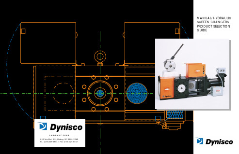
DANGEREMMANUAL SCREEN CHANGEREHHYDRAULIC SCREEN CHANGERThe line of Manual Screen Changers wasdesigned using finite element modeling, insuring leak-free operation up to 10,000 psi —guaranteed!Designed and manufactured by Dynisco in the U.S., these screen changers feature a patented pressure activated seal that allows processing of polymers up to 850°F . The seals are designed to be accessible through the slide plate opening, allowing service with no machine disassembly.Another feature of the Manual Screen Changer is it’s unique multi-position handle design. This safety and convenience feature helps avoid interferences and allows better operator access to the screen changer.Available close-coupled extruder connections are cost-efficient and save processors money by eliminating c-clamp costs. Same day delivery is available with customer-supplied adapters.The Manual Screen Changer is suitable for virtually any extrusion process that can tolerate a momentary shutdown to change screens.Six manual screen changer models are available from 1" through 4.5" (25mm –120mm), all with the capability of pulling the extruder screw through the screen changerwhile mounted on the barrel.Features:•Multi-position handle•Major components designed by finite element modeling •Patented pressure activated seal •Standard machines in stock •Close-coupled extruder connections available•Six models available from 1" through 4.5"(25mm –120mm)•Designed and built in the U.S. by DyniscoBenefits:Avoids interferences and provides better operator accessCost-efficient designguaranteed for leak-free operation up to 10,000 psiAllows leak-free processingfrom 0–850°FSame day deliveryavailableAdapters are cost-efficientand designed for optimum flow rheology. Thread-on adapters are available,eliminating c-clamp costsExtruder screws may bepulled through the screen changer while mounted on the barrelUnmatched price, delivery,and after sales serviceThe EH Hydraulic ScreenChangers were designed with the most impressive list of features available.Designed using finite element modeling for operation up to 10,000 psi, pressure drops to 3000 psi and processing temperatures up to 850°F .Close coupling to the extruder is available with the standard bolt through extruder connection.The EH screen changer comes fully assembled, pre-wired and requires only a single temperature control zone.Dynisco provides full time, total support — without compromise,Features:•Bolt through extruder connection standard•Finite element modeling•Pressure activated seal •New breaker plate•Tamper resistant safety switches •Four hydraulic EH Screen Changer models available from 2.5" to 6.0"•Complies with NFPA-79and European CE specificationsBenefits:Easier installation better sealing with improved reliabilityCost-efficient design foroperation up to 10,000psi and pressure drops to 3000 psiAllows leak-free processingfrom 0–850°F24% more screen areaand improved retentionSafetyExtruder screw may bepulled through the screen changer while mounted on barrelStandard unit designed forworldwide useEH-EM Seals。
Endress+Hauser TPC200高温传感器说明书

Products Solutions Services TI01016T/09/EN/02.1371236165Technical InformationTC insertTPC200With ceramic isolatorFor installation in high temperature assembliesof TAF seriesThermocouple sensor types J, K, R, S, BApplication•Replaceable insert for installation inhigh temperature assemblies TAF11 and TAF16•Thermocouple sensors measuring range up to +1700°C (+3092 °F)Your benefits•Customized immersion length•Single or double measurement junction•Selection of different TC wire diametersTPC2002Endress+HauserFunction and system designMeasuring principleThermocouples are comparatively simple, robust temperature sensors which use the Seebeck effect for temperature measurement: If two electrical conductors made of different materials are connected at a point, a weak electrical voltage can be measured between the two open conductor ends if the conductors are subjected to a thermal gradient. This voltage is called thermoelectric voltage or electromotive force (emf.). Its magnitude depends on the type of conducting materials and the temperature difference between the "measuring point" (the junction of the two conductors) and the "cold junction" (the open conductor ends). Accordingly, thermocouples primarily only measuredifferences in temperature. The absolute temperature at the measuring point can be determined from these if the associated temperature at the cold junction is known or is measured separately and compensated for. The material combinations and associated thermoelectric voltage/temperature characteristics of the most common types of thermocouple are standardized in the IEC 60584 and ASTM E230/ANSI MC96.1 standards.Measuring range Performance characteristicsAccuracyPermissible deviation limits of thermoelectric voltages from standard characteristic for thermocouples as per IEC 60584 or ASTM E230/ANSI MC96.1:InputDesignationMeasuring range limitsThermocouples (TC)1) as per IEC 60584Type J (Fe-CuNi)Type K (NiCr-Ni)Type S (PtRh10-Pt)Type R (PtRh13-Pt)Type B (PtRh30-PtRh6)-210… +1200 °C (-346… +2192 °F), typical sensitivity ≈ 55 μV/K -270… +1372 °C (-454… +2502 °F), typical sensitivity ≈ 40 μV/K -50… +1768 °C (-58… +3214 °F), typical sensitivity ≈ 11 μV/K -50… +1768 °C (-58… +3214 °F), typical sensitivity ≈ 13 μV/K 0…+1820 °C (+32... + 3308 °F), typical sensitivity ≈ 9 μV/K1) Typical sensitivity above 0 °C (+32 °F)StandardTypeStandard tolerance Special tolerance IEC 60584ClassDeviationClass DeviationJ (Fe-CuNi)2±2.5 °C (-40...333 °C)±0.0075 |t|1) (333...750 °C)1 ±1.5 °C (-40...375 °C)±0.004 |t|1) (375...750 °C)K (NiCr-Ni)2±2.5 °C (-40...333 °C)±0.0075 |t|1) (333...1200 °C)1 ±1.5 °C (-40...375 °C)±0.004 |t|1) (375...1000 °C)R (PtRh13-Pt) and S (PtRh10-Pt)2±1.5 °C (0...600 °C)±0.0025 |t|1) (600...1600 °C)1±1 °C (0...1100 °C)±[1 + 0.003(|t|1)-1100)] (1100 °C...1600 °C)S (PtRh13-Pt)21B (PtRh30-PtRh6)2±1.5 °C or±0.0025 |t|1) (600...1700 °C)--1) |t| = Absolute temperature value in °CTPC200Endress+Hauser 3Calibration specificationsEndress+Hauser provides comparison temperature calibration from -80 to +1400 °C (-110 °F to 2552°F) based on the International Temperature Scale (ITS90). Calibrations are traceable tonational and international standards. The calibration report is referenced to the serial number of the insert.MaterialSheath materials.The temperatures for continuous operation specified in the following table are only intended asreference values for use of the various materials in air and without any significant compressive load. The maximum operation temperatures are reduced considerably in some cases where abnormal conditions such as high mechanical load occur or in aggressive media.Standard Type Standard toleranceSpecial toleranceASTM E230/ANSI MC96.1Deviation, the larger respective value appliesJ (Fe-CuNi)±2.2 K or ±0.0075 |t|1)(0...760 °C)±1.1 K or ±0.004 |t|1) (0...760 °C)K (NiCr-Ni)±2.2 K or ±0.02 |t|1) (-200 ... 0 °C)±2.2 K or ±0.0075 |t|1)(0...1260 °C)±1.1 K or ±0.004 |t|1) (0...1260 °C)R (PtRh13-Pt) and S (PtRh10-Pt)±1.5 K or ±0.0025 |t|1)(0...1480 °C)±0.6 K or ±0.001 |t|1)(0...1480 °C)S (PtRh13-Pt)B (PtRh30-PtRh6)±0.005 |t|1) (870...1700 °C)±0.0025 |t|1) (870...1700 °C)1)|t| = absolute temperature value in °CIn order to obtain the maximum tolerances in °F, the results in °C must be multiplied by a factor of 1.8.Temperature rangeMinimum insertion length IL in mm (in)-80 °C to -40 °C (-110 °F to -40 °F)200 (7.87)-40 °C to 0 °C (-40 °F to 32 °F)160 (6.3)0 °C to 250 °C (32 °F to 480 °F)120 (4.72)250 °C to 550 °C (480 °F to 1020 °F)300 (11.81)550 °C to 1400 °C (1020 °F to 2552 °F)450 (17.75)Material nameShort formRecommended max. temperature for continuous use in airPropertiesCeramic material types according to DIN VDE0335C6101500 °C (2732 °F)•Al 2O 3-content approx. 60 %, alkali-content 3 %•The most economic non porous ceramic material•Highly resistant to hydrogen fluoride, temperature shocks and mechanical influences, normally used for internal and external thermowells as well as insulators C7991800 °C (3272 °F)•Al 2O 3-content approx. 99.7 %•Can be used for both internal and external thermowells and insulators•Resistance to hydrogen fluoride gases and alkaline vapors, to oxydizing, reducing and neutral atmospheres as well as temperature changes•This material is very pure and has a very low porosity (gas tight) compared to all other types of ceramicsTPC2004Endress+HauserMechanical constructionDesign, dimensionsFig.1:All dimensions in mm (in).The measuring point of the thermocouple is located close to the tip of the insert. The operatingtemperature ranges (→ä2) and permissible deviation limits of the thermoelectric voltages from the standard characteristic (→ä2) vary according to the type of thermocouple used. The thermocouple wires are inserted in appropriate high-temperature-resistant ceramic isolators.ABMeasuring insert with TC type J or K,ceramic segment isolator and mounted terminal block (DIN B)Measuring insert with TC type R, S or B,with external ceramic sheath and mounted terminal block (DIN B)Lg X He Di Immersion length of the assemblies thermowell Additional length, see table below Insert length (He = Lg + X)Diameter insertInsert length He calculation rules (He = Lg + X) TPC200Material high temperature assembly Terminal head DIN B Terminal head DIN A TAF11 thermowell:•C610 + sleeve•Sinterized silicon carbide SIC + sleeve•Special silicon nitride ceramic SiN + sleeveHe = Lg + 15 mm (0.6 in)He = Lg + 5 mm (0.2 in)He = Lg + 10 mm (0.4 in)He = Lg + 30 mm (1.2 in)He = Lg + 20 mm (0.8 in)He = Lg + 25 mm (1.0 in)TAF16 thermowell:•NiCo special nickel/cobalt alloy (metal cap)•All metal thermowells, e. g. 310, 446, 316, etc.•Bar stock tip thermowells NiCo and INCOLOY800HT •Kanthal Super•SiN (special silicon nitride ceramic)•Kanthal AFHe = Lg + 5 mm (0.2 in)He = Lg + 15 mm (0.6 in)He = Lg + 10 mm (0.4 in)He = Lg + 10 mm (0.4 in)He = Lg + 10 mm (0.4 in)He = Lg + 10 mm (0.4 in)He = Lg + 20 mm (0.8 in)He = Lg + 30 mm (1.2 in)He = Lg + 25 mm (1.0 in)He = Lg + 25 mm (1.0 in)He = Lg + 25 mm (1.0 in)He = Lg + 25 mm (1.0 in)When configuring the high temperature assemblies of the TAF family the thermocouple wire diameter also needs to be defined. The higher the temperature the larger the wire diameter needs to be selected. A large wire diameter will also increase the lifetime of the sensor.TPC200Endress+Hauser5WeightDepending on length and diameter, e. g. 0.1 kg ( 3.53 oz) for Lg = 580 mm (22.8 in) and diameter 8 mm (0.3 in).WiringWiring diagramsThermocouple wire colorsType of insert Wire diameter in mm (in)Insert diameter in mm (in)1x K, 2x K, 1x J, 2x J 1.63 (0.06)8 (0.31)1x K, 2x K, 1x J, 2x J 2.3 (0.09)8 (0.31)1x K, 1x J 3.26 (0.13)12 (0.47), 14 (0.55)2x K, 2x J 3.26 (0.13)12 (0.47), 14 (0.55)1x S, 2x S0.35 (0.014) 6 (0.24)1x S, 2x S, 1x R, 2x R, 1x B, 2x B0.5 (0.02)6 (0.24)As per IEC 60584•Type J: black (+), white (-)•Type K: green (+), white (-)•Type B: grey (+), white (-)•Type R: orange (+), white (-)•Type S: orange (+), white (-)TPC2006Endress+HauserInstallation conditionsOrientationNo restrictions.Installation instructionsCertificates and approvalsCE MarkThe device meets the legal requirements of the EC directives if applicable. Endress+Hauser confirms that the device has been successfully tested by applying the CE mark.Other standards and guidelines•IEC 60584:Thermocouples •DIN EN 50446:Straight thermocouple assembly with metal or ceramic protection tube and accessories, including terminal headsTest report and calibrationThe "Factory calibration" is carried out according to an internal procedure in a laboratory ofEndress+Hauser accredited by the European Accreditation Organization (EA) to ISO/IEC 17025.A calibration which is performed according to EA guidelines (SIT/Accredia or DKD/DAkks calibration) may be requested separately. The calibration is performed on the replaceable insert of thethermometer. In the case of thermometers without a replaceable insert, the entire thermometer - from the process connection to the tip of the thermometer - is calibrated.Observe the insert length calculation rules. →ä4Fig.2: Insert installationThe TPC200 insert is mounted in high temperatureassemblies of the TAF1x series with a flat face terminal head as per DIN EN 50446.TPC200Endress+Hauser 7Ordering informationDetailed ordering information is available from the following sources:•In the Product Configurator on the Endress+Hauser website: È Select country È Instruments È Select device È Product page function: Configure this product•From your Endress+Hauser Sales Center:/worldwideDocumentationTechnical information:High temperature assembliesOmnigrad S TAF11, TAF12x, TAF16 (TI00251T/09/en)Product Configurator - the tool for individual product configuration:•Up-to-the-minute configuration data•Depending on the device: Direct input of measuring point-specific information such as measuring range or operating language •Automatic verification of exclusion criteria•Automatic creation of the order code and its breakdown in PDF or Excel output format •Ability to order directly in the Endress+Hauser Online Shop。
纳伊尔工业有限公司产品说明书:火抗性天花板空气散布器安装说明书
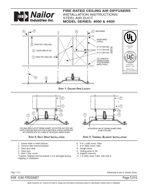
Nailor Industries Inc. reserves the right to change any information concerning product or specification without notice or obligation.Page"C o m p l e t e A i r C o n t r o l a n d D i s t r i b u t i o n S o l u t i o n s."w w w.n a i l o r.c o mCalgary, Canada Tel: 403-279-8619Fax: 403-279-5035Houston, Texas Tel: 281-590-1172Fax: 281-590-3086Toronto, Canada Tel: 416-744-3300Fax: 416-744-3360Las Vegas, Nevada Tel: 702-648-5400Fax: 702-638-0400Page 5.0119/09 IOM-FRDSINST 1.Follow carefully steps 1, 2 and 3.2.Before installing, open damper blades and install link between spring loaded wire clips. Do not bend or deform clips after assembly. If dampers are provided with link tabs instead of wire clips, install link and bend tabs to secure link in positione 12 swg galvanized steel hanger wires to independently support the T-bar grid members and the support channels to the structural members of the floor or roof above at the four corners of the diffuser.Ensure hanger wires are plumb and straight.4.When installing the Ceiling Air Diffuser in duct drop, use #8 by 1/2" (13) long sheet metal screw s - 4 per diffuser. The screws shall not interfere with the closing of the Integral Classified Ceiling Damper of the Ceiling Air Diffuser Assembly.5.Support the duct with 2 - 16 gauge cold rolled steel support channels, 1 1/2" (38) deep with 1/2" (13)flanges. Place the support channels at the bottom of the duct adjacent to both sides of the duct drop.6.Maximum neck size of Series 4000 and 4400 Ceiling Air Diffuser is 14" (356) diameter.7.The clearance between the Ceiling Air Diffuser neck and the duct drop shall be 1/8" (3) maximum.8.No diffusers shall be located in an adjacent 24" x 48" (600 x 1200) ceiling grid module.9.Series 4000 and 4400 Ceiling Air Diffuser Assemblies are for use in lieu of the hinged blade, sheet metal damper in steel ducts with steel diffusers or grilles as specified in the "Design Information Section -General" and in the individual floor and roof ceiling design(s) being used, as illustrated and described in the current UL "Fire Resistance Directory" or ULC "List of Equipment and Materials".10.Fire resistive designs must cover UL/ULC Classified Ceiling Grid Members with appropriate cross tee sizes and slots in cross tees.The following manufacturers currently supply 1'- 0" (300) long cross tees that are UL and/or ULC Classified:-Armstrong World Industries Inc.-CGC Interiors, Division of CGC Inc.-Chicago Metallic Corp.-USG Interiors Inc.Cartons of Grid Members shall be of the same type and bear the UL and/or ULC Classification marking.Page 2 of 2Dimensions are in inches (mm).。
耐高温卷式膜

耐高温卷式膜
埃姆媞HT系列产品专门为采用热水消毒法以避免使用化学消毒法的系统而设计,以提高产品质量或满足行业法规标准,热消毒耐受90℃(194℉)。
适合于低错流环境、无悬浮固体、工作温度为50℃(122℉)的水净化分离系统。
卫生级膜组件,适合制药,食品,化妆品等用户使用。
埃姆媞高温热消型卷式膜操作和清洗参数
操作压力:600psi
典型操作压力:225psi / 110psi
单支膜压降:<12psi
回收率:15%
操作温度:50℃
清洗温度:90℃
连续工作PH范围:4-11
清洗PH范围:2-11.5
允许余氯含量:500ppm-h
进水:NTU<1 SDI<5
埃姆媞高温热消型卷式膜行业应用油田回注水净化
注射用高纯度水的热消毒
牛奶浓缩
锅炉冷凝液回收
纺织工业中染色冲洗水回收
合成氨化工厂冷凝水回收。
迪克森蒸汽类产品介绍说明书

Blank 1Terminal ProductsCustomer Service800.789.1718Dixon Sanitary Solutions for Wineries, Breweries, and Distilleries1 877.963.4966 • RZL-Series Positive Displacement PumpsApplications • Unloading • Fluid transfer • Metering • CIP supply Material • 316LFeatures• Front loading seals • Various rotor options • 100 to 300 models stainless steel gear box standard • 3A and EHEDG certified • CIP certified Sizes• 1" to 10"Centrifugal Pumps Applications • Unloading • Transfer • CIP supplyMaterials • 316L • B una-N, EPDM, silicone, and FKM elastomersFeatures • W et ends, motor pump units, and carts • 3A certified for CIP Sizes• Inlet 1" to 6"•Outlet 1-1/2" to 4"BC/BP-Series ExD-SeriesMB100-SeriesFeatures B5107• V arious actuation and control packages• Multiple handle options • S eat materials: silicone, EPDM, and FKM elastomers B5116• Silicone seat material only • M anual handle only; cannot be actuatedApplications • Isolation • Control Materials• B5107: 316L •B 5116:304Sizes•1/2" to 8"B5107 and B5116-Series Butterfly ValvesB5107-Series B5116-SeriesBV2C-Series Ball ValvesApplications • Isolation • Diversion • Control Material • CF8MFeatures • 5 encapsulated seat materials available • I SO 5211 mounting pad standard• Optional 2-way V-port seat • V arious actuation and control packages Sizes•1/2" to 4"2Dixon Sanitary800.789.1718 • TV-Series Tank Vent ValvesApplications• Liquid filtration Materials • 316LCartridge Element Options •M elt blown •P ES • PHE • Carbon• Stainless steelSizes• Port connection - 1" to 4"• N umber of elements - 1, 3, 5, 7, 12, and 21• C artridge element lengths -10", 20", 30" and 40" SwivelsFeatures• Clamp or weld connection • A vailable in Styles 20 through 70•3A certified for COP Sizes • 1" to 4"Applications • T o rotate hose assemblies without disconnecting Materials • 316L•Silicone or EPDM gasketsStyle 20Style 40Sanitary FiltrationTopping Gun, Gauges, Sample Valves, Sight Glasses, andSpray BallsSightGlassesPressureGaugesSpray BallsSample ValvesToppingGunFeatures PVC • P VC with 304 stainless steel dome • 2" and 3" clampconnections on same valve Stainless Steel • S tainless steel valve • Stainless steel screen •2", 3", and 4"PVC Stainless SteelApplication • S econdary tank protection during filling or draining of tanks3Dixon Sanitary800.789.1718 • 4877.963.4966 • Blank 1Terminal Products© 2021 DVCC Printed in the USA BSWBB_523N25 W23040 Paul Road, Pewaukee, WI 53072Phone: 800.789.1718Fax: 800.789.1046Dixon Sanitaryconnect with us on。
赞尼特高温应用旋转外齿泵H系列说明书

Zenith ®Pumps Precise, Pulseless,Repeatable Performance In High-T emperature Applications.H-SeriesGear PumpsThe H-Series pumps are ideal for metering in such applications as:Zenith ®Pumpstoday–diaphragm, lobe, coarse gear, pis-ton, plunger, and screw pumps. Each had problems with pulsation, flow inaccu-racies, multiple seal areas and slippage,which required constant calibration, high maintenance, and extended downtimes.Zenith Pumps met the challenge and designed a rotary external gear pump of unique precision and simplicity. Manufac-turing techniques were developed to hold tolerances to +.00005" minimizing internal clearances to assure accurate and precise metering. The pump’s simplistic design of only three moving parts–two metering gears and a drive shaft–provided long life and easy maintenance.For years since, process engineers have relied on Zenith to provide precision fluid handling solutions for their most difficult pumping applications. Zenith gear pumps can be found wherever precise, pulseless,repeatable metering of fluids is required.In 1926, Zenith Pumps was approached by the synthetic fiber industry to design a pump to provide a precise, pulseless, re-peatable flow and assure better quality control. The options then were the same as those in the chemical process industryHigh Accuracy.Stable, repeatable flows are assured even under varying conditions of pressure, viscosity and temperature.Minimum Pulsation. Unique design offers virtually pulseless flow without valves or flexible elements to hinder performance.Pump Type:Rotary external spur gear, single stream.Rotation:Refer to pump drawing.Operating Speed:3–180 rpm depending upon application conditions and fluid viscosity.Temperature:To 950°F (510°C).ApplicationsStandard ZeDRIVE with 1/2 hp QM and rear-port HMB pumps.High Temperature Capability.Operating temperatures to 950°F (510°C).Maximum Life.Only three moving parts;components are through-hardened tool and die steels to 64 R c or better.Replaceable sleeve bear-ings for low-cost rebuilds.High Volumetric Efficiency.Maximum efficiency is achieved with optimum operating clearances and assured under pressure by built-in alignment dowels.Precision Construction. Ground and lapped components for close of operating clearances.FeaturesSpecificationsAdhesives Additives Asphalt Abrasives Bottoms Foams Coatings Inks Fibers Pitch Urethanes Surfactants Oxide Slurries Lubricants Polymers Plasticizers Polyols Plastics Paints ResinsMonomersOilsPigments TarsMany othersHMB PumpFlow Rates:.00013 to 0.14 gpm (.00048-.526 l/min).Capacities:.16/.297/.584/1.168/1.752/2.92 cc/rev.Inlet Pressure:Flooded suction recommended;40 psi (2.8 kg/cm 2) required to energize mechanical face seal.Discharge Pressure:Limits: 4,000 psi (281 kg/cm 2).Viscosity:1 to 2,000,000 cps.Mounting:L-16 Parco-Lubrited cast iron mounting saddle.Materials of Construction:D2 tool steel–Models 4647 and 5556.M series tool steel–Models 5205 and 5557.Model 5704 available in either D2 or M series.Seals:Grafoil Packing–Model 5704.Mechanical face with tang slot–Models 4647 and 5205.Mechanical face with outer drive shaft–Models 5556 and 5557.Flow Rates: .0028 to .476 gpm (.011-1.8 l/min).Capacities:3.5/5.5/10.0 cc/rev.Inlet Pressure:Flooded suction recommended;40 psi (2.8 kg/cm 2) required to energize mechanical face seal.Discharge Pressure:Limits: 4,000 psi (281 kg/cm 2).Viscosity:1 to 2,000,000 cps.Mounting:L-5471 Parco-Lubrited cast iron mounting saddle.Materials of Construction:M2 tool steel–All standard models.Seals:Grafoil Packing–Model 5740.Mechanical face with tang slot–Model 4892.Mechanical face with outer drive shaft–Model 5555.HXB PumpFlow Rates: .008 to 2.4 gpm (.03-9.0 l/min).Capacities:10/20/30/50 cc/rev.Inlet Pressure:Flooded suction recommended;40 psi (2.8 kg/cm 2) required to energize mechanical face seal.Discharge Pressure:Limits: 4,000 psi (281 kg/cm 2).Viscosity:1 to 2,000,000 cps.Mounting:L-5139 Parco-Lubrited cast iron mounting saddle.Materials of Construction:D tool steel–All standard models.Seals:Grafoil Packing–Model 5592.Mechanical face with tang slot–Model 4729.Mechanical face with outer drive shaft–Model 5548.Flow Rates: .055 to 9.5 gpm (.21-36 l/min).Capacities:70/100/147.5/200 cc/rev.Inlet Pressure:Flooded suction recommended.Discharge Pressure:Limits: 4,000 psi (281 kg/cm 2).Viscosity:1 to 2,000,000 cps.Mounting:L-5427 Parco-Lubrited cast iron mounting saddle.Materials of Construction:M series tool steel–All standard models.Seals:D-110 Packing–Model 4980.Selection Guide5)Determine differential pressure (P)(discharge - inlet) in psi.6)Calculate input torque using the following:T h = .01• P • C T v = N • K • V T t = T h + T v7)Determine maximum torques from Table 2.8)Choose a speed reduction ratio (R) basedon pump operating speed.R = 22:1; 4 - 82 rpm R = 11:1; 8 - 160 rpm R = 5:1; 18 -180 rpm9)Drive Horsepower = T t / (35 • R • .87)10)For hp <.5 choose .5 hp.For hp between .5 and 1.0 choose 1 hp.For larger hp round up to the nearest whole number.The following are general guidelines for pump selection and should be confirmed with the factory or sales representative before ordering.1)Choose appropriate pump capacitybased on flow rate. (See Chart 1)2)Determine pump operating speed (N).N = Flow Rate (cc/min)÷(C) Pump Capacity (cc/rev)3)Determine operating viscosity (V) inpoise. If fluid is non-newtonian, follow steps 3a and 3b.3a)Identify pump’s operating shear rate.(See Chart 2)3b)Refer to your viscosity vs. shear ratecurve for operating viscosity (V) in poise.4)Refer to Table 1 for pump constant (K).Pump Capacity Selection ChartChart 1Shear Rate vs. SpeedChart 2Constant (K)Table 2Maximum T orque© Copyright 1996 Zenith Pumps H-02 10/04Zenith ®Pumps1710 Airport Road Monroe, NC 28110Phone: 704-289-6511 • Fax: 704-289-9273**************************•A Colfax Buisiness UnitISO 9001: 2000 Registered。
- 1、下载文档前请自行甄别文档内容的完整性,平台不提供额外的编辑、内容补充、找答案等附加服务。
- 2、"仅部分预览"的文档,不可在线预览部分如存在完整性等问题,可反馈申请退款(可完整预览的文档不适用该条件!)。
- 3、如文档侵犯您的权益,请联系客服反馈,我们会尽快为您处理(人工客服工作时间:9:00-18:30)。
高温熔体压力传感器使用说明书
1.传感器安装注意事项:
1.1 注意保护产品与介质接触部位,在安装前尽量不要取下产品的保护帽。
1.2 设备开孔需采用专业的开孔工具严格安装我司开孔尺寸开孔并保证孔内无杂质和毛刺。
1.3 螺纹安装时安装扭矩不得超过56N.m.最好在安装前在螺纹处涂抹防脱化合物。
法兰连接时,每个螺栓的预紧力要基本一致。
2.传感器拆卸注意事项:
2.1 清洁设备前必须拆下所有传感器;只有当聚合物为熔融状态下才能拆下传感器并立即用软布将探头部分擦净。
2.2 传感器拆后,需用专业的清理工具对孔进行清理,以便下次安装。
3.安装环境要求:
3.1 传感器外壳部分必须固定在80℃以下温度处和不得暴露在水中或潮湿的环境中。
3.2 设备启动时确保物料为熔融状态,避免低温干扰,从而损坏传感器。
4.过载影响:
传感器的量程最好为被测压力源的2倍,传感器需避免长时间过载(产品设计过载能力为1.5倍额定压力)。
5.电缆线连接:
输出信号电缆线必须通过布线槽进行连接,同时需要屏蔽线单独接地,避免现场干扰。
6.零点和满度调节(仅指变送器):
6.1“Z”代表零位调节,“S”满度调节。
拧开并取下Z和S处螺钉,用一字螺丝刀内置电位器,在无压力状态下调节零点
6.2 零点调节和满度调节方向:顺时钟方向为增大,反之为减小。
6.3 一键清零产品调节零点时,只需取下螺钉,用螺丝刀轻按一下内置电位器即可。
9.常见故障及排除:
9.1 变送器信号输出不稳:
a.压力源本身是一个不稳定的压力;b.仪表或压力传感器抗干扰能力不强;c.传感器接线不牢或者接线部分老化
d.传感器本身振动很厉害;e.传感器故障9.2 变送器接电无输出:
a.接错线(仪表和传感器都要检查);b.导线本身的断路或短路;c.电源无输出或电源不匹配;d.仪表损坏或仪表不匹配9.3.机械部分故障:
A.探头处有损伤:a.开孔过小;b.开孔与螺纹不同心;c.在低温时拆卸传感器。
B.螺纹损坏:a.安装扭矩过大;b低温时拆卸传感器;c.开孔尺寸不对。
尊敬的用户:
非常感谢选用我司的产品!在您使用产品之前,请仔细阅读此说明书
8.售后服务:
8.1 产品出现故障时切勿自行修理,请于本公司联系,本公司会及时予以反馈。
8.2 产品保质期为一年,在保质期内如有质量问题,本公司负责免费维修或更换。
8.3 产品终身维修。
8.4 以下情况不属于免费维修或更换之列:
a.未按产品使用说明正确安装,使用等人为造成的损坏。
b.用户自行拆开我司产品。
c.产品外观零件严重受损。
7.产品供电:
a.毫伏信号输出:10Vdc;b.电流和电压输出:12-30Vdc
满度调节校验用,非专业人士不得调节。
e.传感器损坏
法兰密封安装孔尺寸表
10.安装孔尺寸及密封方式
11.安装孔正误示意图
12.电气连接
4-20mA输出信号直接引线电源+地线电源-线端颜色
白色
红色黑色4-20mA+Hart
备注:
选择不同的电气连接,接线时请参考我们上面提供的对应的接线方法,参考各线的颜色来接线即可,如不带电缆线,须按引脚的功能来接线。