超级终端配置comtech CMR-5975 接收机
AP超级终端配置

AP超级终端配置订货会AP的配置方法POE模块与AP接法:POE的DATA&POWER口接AP的GE1/POEPOE的DATA IN接交换机或电脑的网口串口线(设置线)接AP的CONSOLE口再接到电脑的串口或USB转串口安装USB转串口驱动在设备管理器中,设置USB转串口(串口号:COMXX, 波特率:19200)打开超级终端SecureCRT设置协议为:Serial 端口号: COMXX 波特率:19200ap7131-6AEF9C login: adminPassword: motorola系统默认密码不显示System is currently using the factory default login credentials.Please change the default password to protect from unauthorized access.Enter new password: 输入新密码不显示Confirm new password: 再次输入新密码不显示Password for user 'admin' changed successfully.Please write this password change to memory ("write memory") to make the change persistent. ap7131-6AEF9C>enable 进入特权模式1、设置国家时区ap7131-6AEF9C#conf t 进入全局设置模式ap7131-6AEF9C(config)#rf-domain default .................射频区域默认ap7131-6AEF9C(config-rf-domain-default)#country-code cn 设置国家CNap7131-6AEF9C(config-rf-domain-default)#..2、管理地址设置en 在特权模式下ap7131-6AEF9C#ap7131-6AEF9C#self进入设备自身设置Enter configuration commands, one per line. End with CNTL/Z.ap7131-6AEF9C(config-device-B4-C7-99-6A-EF-9C)#in vl 1新进vlan 1ap7131-6AEF9C(config-device-B4-C7-99-6A-EF-9C-if-vlan1)#ip add 192.168.1.250/24输入IP地址、掩码24位(255.255.255.0)ap7131-6AEF9C(config-device-B4-C7-99-6A-EF-9C-if-vlan1)#comm wr 保存3、管理设置使用conf t 进入全局配置模式下ap7131-6AEF9C(config)#ap7131-6AEF9C(config)#management-policy defaultap7131-6AEF9C(config-management-policy-default)#telnet 开启telnetap7131-6AEF9C(config-management-policy-default)#http server开启httpap7131-6AEF9C(config-management-policy-default)#..4、设置WLAN 无线连接密码!设置Wlan 在全局模式下设置ap7131-6AEF9C(config)#ap7131-6AEF9C(config)#wlan motorola 设置Wlan名称motorolaap7131-6AEF9C(config-wlan-motorola)#vlan 1 绑定vlan 1ap7131-6AEF9C(config-wlan-motorola)# bridging-mode local本地转发(桥接)如果在AP上配置的话,默认为本地转发(localmode), 如果此wlan是在控制器上配置的话,则默认为集中转发(tunnel mode)ap7131-6AEF9C(config-wlan-motorola)#encryption-type ccmp设置加密方式为CCMPap7131-6AEF9C(config-wlan-motorola)#wpa-wpa2 psk 0 qwertyui设置密码: qwertyuiap7131-6AEF9C(config-wlan-motorola)#sho con 查看WLAN 配置wlan motorolassid motorolavlan 1bridging-mode localencryption-type ccmpauthentication-type nonewpa-wpa2 psk 0 qwertyui5、DHCP的配置ap7131-6AEF9C(config)#dhcp-server-policy default DHCP设置default是策略的名字ap7131-6AEF9C(config-dhcp-policy-default)#dhcp-pool 10名字ap7131-6AEF9C(config-dhcp-policy-default -pool-10)#network 192.168.1.0/24网段ap7131-6AEF9C(config-dhcp-policy-default-pool-10)#address range 192.168.1.10 192.168.1.240 IP池ap7131-6AEF9C(config-dhcp-policy-default-pool-10)#default-router 192.168.1.250路由(如果公司有路由器,那么要设公司的路由器地址)ap7131-6AEF9C(config-dhcp-policy-default-pool-10)#dns-server 192.168.1.250 DNS (如果公司有DNS,那么要设公司的DNS地址)ap7131-6AEF9C#comm wr 保存!如果只有一个AP,就此结束;, ap7131-380CFC(config-dhcp-policy-default)#show con 查看配置查看DHCPap7131-6AEF9C# show ip dhcp binding使用下面命令检查dhcp 是否工作:ap7131-380CFC(config-device-FC-0A-81-38-0C-FC)#show ip dhcp status6、设置radio信号绑定ap7131-6AEF9C(config)#profile ap71xx default-ap71xx 进入全局配置(下发配置设置)所有71型号的信号绑定profile下ap7131-6AEF9C(config-profile-default-ap71xx)#in radio 1ap7131-6AEF9C(config-profile-default-ap71xx-if-radio1)#wlan motorola bss 1 primary 信号绑定motorola 进入自身这台进行设置。
超级终端设置
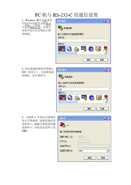
PC机与RS-232-C的通信设置1、Windows XP中开始菜单中程序中的附件中的通讯中选择超级终端,并执行。
该程序运行后出现如右图的画面。
2、设定新建连接的名称输入CNC(或其它),并选择连接的图标,如右图所示。
3、完成第2步设定后按确定显示右图画面,选择连接时使用的串口,根据计算机的资源选择串口,本机设定的串口是COM1。
4、完成第3步设定后,按确定显示右图画面,进行串行通信参数的设定,波特率:9600(根据系统设定参数而定)数据位:8奇偶校验位:无停止位:1数据流量控制:Xon/Xoff5、然后设定CNC超级终端的属性,如右图方法进行设定,选择文件菜单中的属性,并执行。
6、进行设定CNC的属性,在设置的画面中如右图所示进行选择设置。
7、用鼠标点击上图【ASCII码设置(A)】进行设定ASCII码的画面设置,如右图所示选择设定。
8、在以上的设定完成后,就可以进行计算机与数控系统通信了,以下程序以I049-N11Pa.TXT为例,进行通讯。
(1)当接收数控系统的参数信息时,按下列步骤进行操作。
如下图在【传送】菜单中选择捕获文字。
选择【捕获文字】后出现下图画面选择【浏览(B)】新建文件名I049-N11Pa.TXT,并指定保存路径D:\盘。
如下图,并执行【启动】数控系统选择【OUTPUT】键执行输出参数备份。
(2)当发送数控系统的参数信息时,首先将数控系统按【INPUT】处于接收状态,然后设定计算机的状态,按下列步骤进行操作。
如下图在【传送】菜单中选择发送文本文件。
选择【发送文本文件】后出现下图画面选择指定参数文件名选择D:\IO49-N11Pa.TXT 文件名后执行【打开】进行输入参数。
如下图在传输参数中的状态。
卫星应急通信各种设备基本端口连接
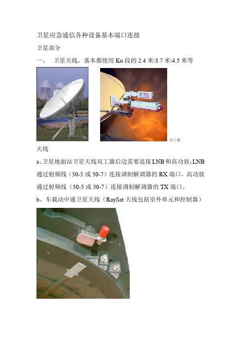
卫星应急通信各种设备基本端口连接卫星部分一、卫星天线,基本都使用Ku段的2.4米\3.7米\4.5米等双工器天线a、卫星地面站卫星天线双工器后边需要连接LNB和高功放;LNB 通过射频线(50-5或50-7)连接调制解调器的RX端口,高功放通过射频线(50-5或50-7)连接调制解调器的TX端口。
b、车载动中通卫星天线(RaySat天线包括室外单元和控制器)A、室外单元需要在相应端口:RX端通过射频线(50-5或50-7)连接调制解调器的RX端口、TX通过高频线连接高功放再通过射频线(50-5或50-7)连接调制解调器的TX端口、CTRL端口通过控制线连接天线控制器Ant in。
B、天线控制器包括:Ant in控制口,IDU LAN口、Sport1、DCin、开关等a、Ant in控制口与天线CTRL连接b、IDU LAN口与网络交换机连接c、Sport1与调制解调器连接d、DCin与DC12V开关电源连接二、卫星高功放(Weavestream MBB-KUS080、ADVANTECH SSPB-60K)以Weavestream为例端口包括:RFoutput输出、IFinput输入、供电、测试四个端口及一个状态指示灯a、RFoutput输出端口通过高频线或波导管连接卫星天线双工器b、IFinput输入端口通过射频线(50-5、50-7)连接调制解调器TX端口c、供电根据需要连接AC220V交流(80W)电或DC48V直流(8W、16W、40W)电源d、测试端口连接频普仪等设备监测用(一般不需要)三、卫星调制解调器(如comtechCDM-570L、CDM-600L,DATUM PSM-500L、IDIRECT等)以CDM-570L为例端口包括RX、Console、Traffic、10/100 Ethernet、Remote Control、TX等a、RX连接地面站天线LNB或动中通天线RX端口b、Console用570自带电缆连接电脑超级终端进行参数配置c、Traffic数据传输接口d、10/100 Ethernete、TX连接高功放的IFinput输入端口。
Omega UWTC-REC3 无线到以太网接收器用户指南说明书

e-mail:**************For latest product manuals:Shop online at®User’s GuideUWTC-REC3The UWTC-REC3 Wireless Receiver provides Web-based monitoring of Temperature and Humidity thru an integrated Web Server or standard TCP/IP telnet commands. Each Receiver can directly support up to thirty-two (32) Thermocouples, RTD, Infrared and Humidity wireless Connectors /Transmitters.ConnectionsThe UWTC-REC3 may be connected directly to the Ethernet port on a computeror connected to a network thru a network router/switch. If connected directly to a computer an Ethernet cross-over cable is required. The device is powered from a wall mount AC power adaptor.Configuration SwitchesNETWORK CONFIGURATION Ethernet (MAC) AddressThe MAC (Media Access Control) address relates the computer IP address to the computer’s physical (MAC) address. The MAC address can be found on the label of your device and contains 6 bytes of hexadecimal numbers XX:XX:XX:XX:XX:XX hex. For Example: 0A:0C:3D:0B:0A:0B IP AddressThe Receiver is shipped with a default IP address of 192.168.1.200 and Subnet Mask of 255.255.255.0. If using a Web browser or Telnet program to access the Receiver using its default IP address ensure that the PC has an IP address that is in the same range as the Receiver’s IP address (192.168.1.x, where x can be any number from 1 to 254). Your PC’s IP address cannot be the same as the Receiver’s IP address.The PC’s Subnet Mask is 255.255.255.0. If 192.168.1.200 is already in use on yournetwork, use an Ethernet crossover cable between your computer and the Receiver to change the IP address or any other settings. Network ProtocolsThe Receiver uses standard TCP/IP protocols as well as supporting ARP , HTTP (WEB server), DHCP , DNS and Telnet protocols.DHCPDHCP (Dynamic Host Configuration Protocol) enables computers and devices toextract their IP configurations from a network hosted server (DHCP server). If DHCP is enabled on the UWTC-REC3 there is an exchange of information between the network DHCP server and the Receiver, allowing the DHCP server to assign the UWTC-REC3 IP address, Gateway address, and the Subnet Mask. DNSDNS (Domain Name System) enables computers and devices to be recognized over a network based on a specific name instead of IP addresses.For example, instead of having to use http://192.168.1.200 (IP address) a user assigned 16 character device name may be assigned, such as http://BoilerTemp. The device name stored as Host Name under Access Control menu in the Wireless System Home Page.The default DNS name for the Receiver is “z” followed by the last four digits of the MAC address of that particular Receiver.Device ConfigurationThe device may be configured using a standard Web Browser or using the iConnect software that may be downloaded at no cost.Web Browser (Direct Connection)Using an Ethernet cross over cable connect the REC3 receiver to the com-puter Ethernet port. The TCP/IP properties on the computer must be con-figured to match those of the REC3 Receiver. Go to the computer ControlPanel/Network Connections screen, right click on the Ethernet adaptorand select properties:You can access the Coordinator’sweb server via any internet browserusing IP address of 192.168.1.200.Once you log into the Coordina-tor’s web server, you will be able tochange its IP configuration accordingto Section 4.2.After you configure the Coordinator’s IP configurations, you should go back and set your PC’s previous IP settings.Open a standard web browser (Internet Explorer, Firefox etc.) and connect to the device:http:// 192.168.1.200, default is shown.iConnect ConfigurationDownload and install the iConnect software from the web site listed below. iConnect is compatible to Windows 95, 98, NT, 2000, XP , Win 7 and Win 8. Use the iConnect to assign a new IP address to the REC3 receiver. Select the View Webpage (#4) button to view the REC3 web server.REC3 Web ServerThe REC3 is an integral web server that allows configuring and monitoring the receiver and remote UWTC probes.Access ControlThe Access Control screen allows setting the IP Address and access control passwords. The default ADMINSTRATOR password is 00000000. An administrator may change any parameter. The default LOGIN password is 12345678. Using the LOGIN password allows changing all parameters except those on the Access Control page.Transmitter ConfigurationWhen a transmitter is powered on the GREEN LED will blink, indicating that it is transmitting data. If no receiver acknowledges the data the transmitter will enter a sleep mode to conserve battery power. The UWxx series can be configured using the TC Central software as described in the UWTC manual.FACTORY PRESET V ALUESWARRANTY/DISCLAIMEROMEGA ENGINEERING, INC. warrants this unit to be free of defects in materials and workmanship for a period of 13 months from date of purchase. OMEGA’s WARRANT Y adds an additional one (1) month grace period to the normal one (1) year product warranty to cover handling and shipping time. This ensures that OMEGA’s customers receive maximum coverage on each product.If the unit malfunctions, it must be returned to the factory for evaluation. OMEGA’s Customer Service Department will issue an Authorized Return (AR) number immediately upon phone or written request. Upon examination by OMEGA, if the unit is found to be defective, it will be repaired or replaced at no charge. OMEGA’s WARRANTY does not apply to defects resulting from any action of the purchaser, including but not limited to mishandling, improper interfacing, operation outside of design limits, improper repair, or unauthorized modification. This WARRANTY is VOID if the unit shows evidence of having been tampered with or shows evidence of having been damaged as a result of excessive corrosion; or current, heat, moisture or vibration; improper specification; misapplication; misuse or other operating conditions outside of OMEGA’s control. Components in which wear is not warranted, include but are not limited to contact points, fuses, and triacs.OMEGA is pleased to offer suggestions on the use of its various products. However, OMEGA neither assumes responsibility for any omissions or errors nor assumes liability for any damages that result from the use of its products in accordance with information provided by OMEGA, either verbal or written. OMEGA warrants only that the parts manufactured by the company will be as specified and free of defects. OMEGA MAKES NO OTHER W ARRANTIES OR REPRESENTATIONS OF ANY KIND W HATSOEVER, EXPRESSED OR IMPLIED, EXCEPT THAT OF TITLE, AND ALL IMPLIED W ARRANTIES INCLUDING ANY W ARRANTY OF MERCHANTABILITY AND FITNESS FOR A PARTICULAR PURPOSE ARE HEREBY DISCLAIMED. LIMITATION OF LIABILITY: The remedies of purchaser set forth herein are exclusive, and the total liability of OMEGA with respect to this order, whether based on contract, warranty, negligence, indemnification, strict liability or otherwise, shall not exceed the purchase price of the component upon which liability is based. In no event shall OMEGA be liable for consequential, incidental or special damages.CONDITIONS: Equipment sold by OMEGA is not intended to be used, nor shall it be used: (1) as a “Basic Component” under 10 CFR 21 (NRC), used in or with any nuclear installation or activity; or (2) in medical applications or used on humans. Should any Product(s) be used in or with any nuclear installation or activity, medical application, used on humans, or misused in any way, OMEGA assumes no responsibility as set forth in our basic WARRANTY / DISCLAIMER language, and, additionally, purchaser will indemnify OMEGA and hold OMEGA harmless from any liability or damagewhatsoever arising out of the use of the Product(s) in such a manner.RETURN REQUESTS / INQUIRIESDirect all warranty and repair requests/inquiries to the OMEGA Customer Service Department. BEFORE RET URNING ANY PRODUCT(S) TO OMEGA, PURCHASER MUST OBTAIN AN AUTHORIZED RETURN (AR) NUMBER FROM OMEGA’S CUST OMER SERVICE DEPART MENT (IN ORDER T O AVOID PROCESSING DELAYS). T he assigned AR number should then be marked on the outside of the return package and on any correspondence.T he purchaser is responsible for shipping charges, freight, insurance and proper packaging to prevent breakage in transit.FOR WARRANTY RETURNS, please have the following information available BEFORE contacting OMEGA:1. P urchase Order number under which the product was PURCHASED,2. M odel and serial number of the product under warranty, and 3. R epair instructions and/or specific problems relative to the product.FOR NON-WARRANTY REPAIRS, consult OMEGA for cur-rent repair charges. Have the following information available BEFORE contacting OMEGA:1. Purchase Order number to cover the COST of the repair,2. Model and serial number of the product, and3. R epair instructions and/or specific problems relative to the product.OMEGA’s policy is to make running changes, not model changes, whenever an improvement is possible. T his affords our customers the latest in technology and engineering. OMEGA is a registered trademark of OMEGA ENGINEERING, INC.© Copyright 2014 OMEGA ENGINEERING, INC. All rights reserved. This document may not be copied, photocopied, reproduced, translated, or reduced to any electronic medium or machine-readable form, in whole or in part, without the prior written consent of Servicing North America:U.S.A.:Omega Engineering, Inc., One Omega Drive, P .O. Box 4047S tamford, CT 06907-0047 USAT oll-Free: 1-800-826-6342 (USA & Canada only)Customer Service: 1-800-622-2378 (USA & Canada only) Engineering Service: 1-800-872-9436 (USA & Canada only) Tel: (203) 359-1660Fax: (203) 359-7700 e-mail:**************For Other Locations Visit /worldwide***********************The information contained in this document is believed to be correct, but OMEGA accepts no liability for any errors it contains, and reserves the right to alter specifications without notice.WARNING: These products are not designed for use in, and should not be used for, human applications.。
chipcon smartrf cc2500单片低成本低能耗RF收发芯片 说明书

500kbps z 较低的电流消耗(RX 中 15.6mA) z 可编程控制的输出功率,可达+1dBm z 优秀的接收器选择性和模块化性能 z 极少的外部元件:芯片内频率合成器,
不需要外部滤波器或 RF 转换 z 可编程控制的基带调制解调器 z 理想的多路操作特性 z 可控的数据包处理硬件 z 快速频率变动合成器带来的合适的频
第 2 页 共 61 页
目录 1 缩写词 ....................................................................................................................... 2 2 绝对最大等级 ........................................................................................................... 5 3 工作条件 ................................................................................................................... 5 4 电气规范 ................................................................................................................... 6 5 常规特性 .....................................................................................
北云GNSS高精度接收机快速使用说明书

GNSS高精度接收机快速使用说明书2018年8月20日目录1 串口数据格式说明 (1)2 基准站和流动站快速切换 (2)2.1 要配置成基准站 (2)2.1.1 方式一:恢复默认配置重启法 (2)2.1.2 方式二:逐条配置法 (2)2.2 要配置成流动站 (3)2.2.1 方式一:恢复默认配置重启法 (3)2.2.2 方式二:逐条配置法 (3)3 基准站和流动站配置 (4)3.1 基准站配置 (4)3.2 流动站配置 (6)4 出厂默认配置 (7)I1串口数据格式说明北云GNSS板卡(接收机)串口数据格式可分为novatel、rtcm、log、fpga四种。
具体定义如下:1)novatel格式:输出标准的NMEA-0183格式协议,具体可见文档《北云GNSS高精度接收机NMEA0183协议说明书》。
2)rtcm格式:基准站模式下默认输出标准的RTCM3.2格式差分数据。
帧头D300开头。
默认输出1074、1084、1114、1124、1006、1033和nav数据帧,不需要单独开启。
默认条件下差分数据量约500字节每秒,卫星数越多,差分数据量越大。
3)log格式:可以输出北云自定义格式的调试信息,便于研发人员进行快速故障定位和数据分析。
4)fgpa格式:可以输出北云自定义格式的原始数据,可用于更深层次的故障定位和数据分析。
注意:1,在novatel格式下,常用指令集均可识别,且指令执行后都会返回“OK”。
2,若需查询串口波特率及格式,可以用log comconfig指令来查询。
3,若需查询各串口输出语句,可用log loglista once 来查询。
4,在rtcm格式下,只识别interfacemode开头的指令。
常用指令集见文档《北云GNSS高精度接收机常用指令集》。
2基准站和流动站快速切换基准站和流动站可以通过串口指令快速切换。
当不确定目前板卡(接收机)是基准站还是流动站时,也可以直接切换。
COMTECH570L设备使用说明
CDM-570L卫星调制解调器设备使用说明注意:所有参数设置,请在中心站管理人员指导下进行!!!一、卫星调制解调器设备介绍本系统卫星调制解调器选用美国ComtechEFData公司生产的CDM-570L。
CDM-570L是一台L波段中频的调制解调器,支持连接LNB和BUC射频设备。
支持快捕解调,可通过升级支持Turbo Product Codec编码,也可升级到支持8PSK 和16-QAM调制。
卫星调制解调器CDM-570LCDM-570L的设计是以固件( firmware)和可编程门阵列(FPGA)为基础, 通过串口可容易地对内部闪存(Flash)进行升级。
在1U的设备封装里提供了高灵活性和出色的性能。
主要性能●950-1950 MHz L波段中频●数据速率从2.4 kbps到5 Mbps●快速捕获解调(±32 kHz捕获范围,64 kbps,1/2 QPSK:平均150毫秒)●最高可支持BPSK,QPSK,OQPSK,8-PSK,16-QAM多种调制方式●前向纠错可支持Turbo Product Codec,维特比,Reed-Solomon和TCM●自动上行功率控制(AUPC)及EDMAC功能●支持非平衡环路时钟●内置1:1备份控制器(Y-电缆用于数据,简单和并非昂贵的外部切换模块用于IF切换)●可支持和连接LNB、BUC●可提供BUC 10MHz参考信号和建立FSK通信,BUC供电电源可选●LNB供电和外10MHz参考●后向兼容CDM-500/CDM-550,CDM-550T和CDM-600、CDM-600L●支持以太监控接口●可选IP数据接口模块●可配外置1:1和1:10冗余切换开关Turbo Product Codec●CDM-570L提供传统的前项纠错(FEC)方式外,还可升级支持TurboProduct Codec (TPC)编码作为选项。
TPC技术提高了编码增益,降低了编码延时,并提供可观的带宽节省。
终端配置
超级终端的连接与使用
一.打开超级终端
开始>> 所有程序>> 附件>> 通讯>> 超级终端
二.设置超级终端
1. 新建连接:
备注:连接“名称”可任意,本例中连接名称为“tr36”
2. 选择端口:
备注:COM1和COM2为硬件端口。
与相机连接时选用X64-CL_iPro_1_Serial_0/1。
当电缆连接在采集卡外端(距离主板远的端口)时,选择X64-CL_iPro_1_Serial_0;
当连接在采集卡内端时,选择X64-CL_iPro_1_Serial_1。
3.设置端口:
首先“还原为默认值”(默认状态见下图),之后根据相机参数设置连接的传输位数,即“每
秒位数”。
4.设置属性:
文件>> 属性(或“属性”快捷键)>> 设置>> ASCⅡ码设置>> 选中“本地回显键入的字符”,使得用户输入的命令可见。
5.测试是否连接成功:
设置完毕后,在输入区按下Enter回车键,出现OK>即表明与相机连接成功。
Agilent 5975T LTM GC-MSD 现场准备指南
提供两种前级泵类型:湿泵是油封旋叶真空泵,干泵是无油的。
所有泵类型可以放在实验室工作台或地板上。它必须靠近 5975T LTM GC/MSD, 因为它使用 160 厘米 (63 英寸)软管连接。软管比较硬,不能大幅度弯曲。
小心
如果实验室工作台上有对震动敏感的设备,则不能将前级泵放在此工作台上。
现场准备指南
13
现场准备工作
最小 间隔 20 厘米 21.2 厘米
21.1 厘米
最小间 隔 20 厘米 图 2 螺栓样式 14
59.1 厘米
在工作台上 6 个位置处钻 0.7 厘米的孔
最小间 隔 100 厘米
现场准备指南
现场准备工作
通讯要求
电话
电话线足够长,便于 5975T 操作人员在计算机旁联系 Agielnt Technologies 支持 人员。
10
现场准备指南
现场准备工作
96 cm (37 ¾ in)
20 cm (8 ¼ in) 65 cm (25 ¾ in)
50 cm (19 ½ in)
41 cm (16 ¼ in)
20 cm (8 ¼ in)
60.8 cm (24 in)
180 cm (5’ 11’’)
100 cm (39 in)
图 1 5975T LTM GC/MS 操作空间要求
5975T LTM GC/MSD 左侧必须至少保留 20 厘米(8 1/4 英寸)的空间,后面必须 至少保留 20 厘米 (8 1/4 英寸)的空间。仪器右侧保留 100 厘米 (39 英寸)的 空间以用于数据系统。仪器右前方保留 28 厘米的空间用以打开 LTM 门。ALS 上 方至少保留 5 厘米的空间用以放置在定位杆上。
使用超级终端抓MG3000-R32的sip协议trace方法
使用超级终端抓MG3000-R32的sip消息trace设置方法使用超级终端工具,telnet MG3000-R32的IP地址端口100,出现如下图,然后选中(工具),里面有捕获文字,点确定后选一个文件存放位置========================================================================================================================================== ==================== VOIP GATEW AY ==================== ==================== V 1.5.1 ==================== ==================== All Rights Reserved ==================== ==========================================================================================================================================Login: userPassword: (密码不显示,实际为user)----------- Welcome to Use VOIP GATEW AY -----------VOIP GATEW AY:>c tThe command has been completed successfully!VOIP GATEW AY:\manage\trace>rtThe command has been completed successfully!VOIP GATEW AY:\manage\trace>stPlease input module ID0--all module1--ether2--DSP3--slic4--trap5--console6--telnet console7--web console10--SNMP11--manage12--SIP protocol13--SIP application : 11Please input port ID(0-32): 0Please input trace type1--entry2--return3--thread4--pipe5--SEM6--MSG7--timer8--memory9--normal10--ACK11--all : 11Please input trace level(1-5): 4Please input trace output mode(1--console 2--buffer): 1 Please input console input mode(1--real time 2--task): 1 The command has been completed successfully!VOIP GATEW AY:\manage\trace>stPlease input module ID0--all module1--ether2--DSP3--slic4--trap5--console6--telnet console7--web console10--SNMP11--manage12--SIP protocol13--SIP application : 13978646130:170000 MANAGE: DspVer is : v6_14978646130:170000 MANAGE: KernelVer is : v1.2.0Please input port ID(0-32): 0Please input trace type1--entry2--return3--thread4--pipe5--SEM6--MSG7--timer8--memory9--normal10--ACK11--all : 11Please input trace level(1-5): 4Please input trace output mode(1--console 2--buffer): 1Please input console input mode(1--real time 2--task): 1The command has been completed successfully!VOIP GATEW AY:\manage\trace>此时trace已经设置好了,拨打电话,会出现很多消息,复现问题后,输入如下命令关闭trace VOIP GATEW AY:\manage\trace>rtThe command has been completed successfully!然后到刚才存放的位置,把文档发邮件提供给工程服务人员。
- 1、下载文档前请自行甄别文档内容的完整性,平台不提供额外的编辑、内容补充、找答案等附加服务。
- 2、"仅部分预览"的文档,不可在线预览部分如存在完整性等问题,可反馈申请退款(可完整预览的文档不适用该条件!)。
- 3、如文档侵犯您的权益,请联系客服反馈,我们会尽快为您处理(人工客服工作时间:9:00-18:30)。
comtech CMR-5975接收机配置方法1.配置超级终端
1.1连接PC与CMR5975
使用CMR5975随机所配备的“终端控制线”连接CMR5975和PC机的RS232接口。
TERM
1.2打开超级终端程序
超级终端程序是Windows操作系统中自带的通信工具,通常用于与设备的监控通信。
在Windows中开启“超级终端”程序,方法为:开始→程序→附件→通信→超级终端。
看到如下界面:
1
2
在上面所示界面中输入一个名字(任意起,比如CMR5975),让后点“OK ”;
1.3 选择通信接口
在弹出的窗口中的“使用连接”栏中选择通信口,通常是“COM1”;
3
1.4 设置超级终端属性
同时需要配置属性页,选择仿真模式(Emulation )为:VT100。
操作方法:在超级终端的界面上,点击工具栏中的属性图标,看到下述配置界面;
在仿真模式栏,选择VT100。
1.5 设置超级终端工作参数
PC 使用超级终端(HyperTerminal )通过控制口(Console )监控和配置CMR5975参数。
超级终端的端口配置为:
∙ 波特率:38400, ∙ 数据位:8 ∙ 校验:无 ∙ 停止位:1 ∙ 流控:无。
选择OK;
2.配置CMR5975
2.1输入用户名和密码
回车,看到登录界面,如下图:
输入用户名和密码。
用户名:comtech
密码:comtech
4
5
2.2 看到主菜单
2.3 配置IP 地址
主菜单下,输入“N ”;看到如下界面:
输入“I ”;看到如下界面:
输入为CMR5975分配的IP地址;
同样的方法设置CMR5975的子网掩码(Subnet Mask) 和默认网关(Default Gateway)。
3.参数配置举例
使用超级终端所看到的界面与Telnet 所看到的界面完全一致,配置完IP地址、子网掩码和默认网关后,就完全可以使用Telnet 来配置CMR5975的参数。
实际网络配置举例如下,CMR-5975的IP地址为:10.200.2.3/28。
a.使用Telnet或Console 串口(超级终端配置参考CDM570L)登录IRD;
b.登录用户名:comtech,密码:comtech
6
c.登录后,主菜单如下;
d.输入字母N,进入网络配置页,参考下面参数配置,网关为CDM570L地址;
e.从主菜单输入字母U进入单播配置页,参考下列参数配置;
7
f.从主菜单输入字母T进入调谐菜单页;
g.在调谐菜单页输入字母C进入调谐配置页,参照主用参数配置Prime;
h.在调谐菜单页输入字母M进入调谐MPE/IP配置页,配置3组PID,参考下图;
8
i.完成所有参数配置后,输入字母S和Y,保存配置;
9
10。