雅科贝思直线电机手册-中文
Eaton xComfort 电动窗帘控制系统说明书
Shading for protection and comfort /xComfort xComfort Shading ControlxComfort Shading ControlMotorized shading control offers residents both comfort and ease of use.By sticking to the basics, however, homeowners miss out on valuable features that go beyond comfort and can help them to save energy and protect their belongings.Situations where enhanced shading control offers added value:•When sunlight causes the room temperature to rise so that cooling is required for comfort, resulting in high energy expenditure•When the blinds are closed but the sunlight could have contributed to reaching the desired room temperature, thereby saving energy•In cold winters when heat loss from the windowsrequires additional heating, resulting in high energy costs •When sunlight ages the furniture, photos, paintings or other valuable items in your home•When your belongings are fully exposed in the evening, and you’re not at home to close the blinds•When you and your family are fully visible to uninvited guests from the outside•Finally, when the shading itself is damaged due toadverse weather such as rain or strong winds Before …Keep the warmth inside…… and after heavy winds….and prying eyes outside.2EATON xComfort Shading Solution Brochure BR610077EN November 2022Additional considerations from installer practice and customer experienceAdded value for installers:•Easy to install and expand, enabling installers to do more in less time •Lighting, heating and shading control via wireless pushbuttons•A high-quality, professional solution that blends well with all types of wiring accessories•Future-proof with upsell potentialFurthermore, especially in existing residential buildings, the placement of the control unit for motorized shading control is often challenging and represents a compromise between what is desired and what is practically possible – and this also applies to new buildings if conventional electrical components are used.These compromises tend to result in the following issues:• Manual operation from a hard-to-reach location •A clunky and ugly design that neither matches nor is integrated with the home’s fixed electrical installation and particularly the existing wiring accessories.• The need for multiple remote controls that are “too” portable, making them hard to find when you really need them•Extensive wiring is required, with flush-mounted boxes and cabling to a shading switch•Only local manual control, with the need to physically press a button or turn a switch •No app control or smart functionsThe solution: xComfort Shading ControlBased on the robust and proven xComfort wireless technology, Eaton has developed xComfort Shading Control whose modern and easy-to-install design allows installers to offer their customers a smart solution for controlling blinds, shutters, zip screens or awnings.A win-win situationOur enhanced shading control package includes several shutter actuator options to increase flexibility of installation and operation. The solution, which is part of Eaton’s xComfort home automation system, is available with slim,flush-mounted actuators (either with or without local inputs) or with a plug-type actuator suitable for outdoor use. In addition, the package features a mains-powered weather station to provide protection and comfort based on precisemeteorological date like sunlight strength, rain, temperature and wind speed.Do you want to put an end to this frustrating situation?3EATON xComfort Shading Solution Brochure BR610077EN November 2022Added value for residents:• Modern 55x55 mm design for asmooth integration with the fixedelectrical installation• High-quality products• Easily expandable as needs grow,e.g., by switching from shade controlwith a single rocker to multiplerockers and pushbuttons accordingto your personal preferences• Holistic home control via a singleapp, including lighting, electricalappliances, heating and shading xComfort Shading Control – a future-proof and flexible solutionxComfort Shutter Actuator – flush-mountedFor controlling motorized blinds• Slim design (18 mm), e.g., for mounting in flush boxes• Mains powered: 230 V AC, 50 Hz• Standby power: <200 mW• For driving 230 V AC motors up to 3 A• With or without local control input for use withmechanical switches• Position-tracking function• Selectable application profiles• Safety position functionxComfort Shutter Actuator – outdoor plug typefor controlling motorized blinds• STAS 3 / STAK 3 Hirschmann connector design• Mains powered: 230 V AC, 50 Hz• Standby power: <230 mW• For driving 230 V AC motors up to 3 A• Operating temperature: -30 to +55 °C• Degree of protection: IP44• Position-tracking function• Selectable application profiles• Safety position function4EATON xComfort Shading Solution Brochure BR610077EN November 2022xComfort Wireless SwitchFor convenient and easy operation from anywhere inside the home and optional with integrated sensors for shading and climate control using the Bridge•55x55 mm design compatible with frames from leading brands•Standard and Multifunctional, with temperature and humidity sensor, types available• Rockers with arrow icons available in different colors • 1-fold, 2-fold and 4-fold versions available • Fully wireless and battery powered • Battery life up to 10 years (TYP)•Flat design that can be mounted anywhere and on any surface – no installation box or wiring needed•Many option to control the shading (Open/Close, Open/Close/Stop, Open/Close/Stop/Step)xComfort Weather StationMeasuring weather conditions for automated shading control•Multi-sensor device:• Wind speed• Brightness (lux) in 3 directions • Rain sensor with integrated heating •Temperature• Mains powered: 100-230 V AC, 50/60Hz • Stand-by power consumption: <5.6 W • Operating temperature: -20 to +55 °C • Degree of protection: IP44•UV-resistance, transparent design for all façade typesxComfort Door/Window SensorFor protecting shading against damage from open doors or windows• Available in different colors • Fully wireless and battery powered •Battery life up to 5 years (TYP)5EATON xComfort Shading Solution Brochure BR610077EN November 2022xComfort Shading Control – product overview and accessoriesActuatorsGlossy rockers withMatte rockers withiconsiconsClassic and multifunctional wireless switchesStandard Switch: 173411CPAD-00/193Multifunctional Switch: EP-50383CPAD-00/2331-fold Standard Switch: 173412CPAD-00/194Multifunctional Switch: EP-50384CPAD-00/2342-fold Standard Switch: 173413CPAD-00/195Multifunctional Switch: EP-50385CPAD-00/2354-foldSensorEP-500527CWSA-04/01WeatherstationDoor/window sensor:300295CDWA-01/3b Bright white 300294CDWA-01/3a Warm white 300296CDWA-01/3c Grey 300297CDWA-01/3dBrown109383CHSZ-02/02Remote control 2 Channels 109384CHSZ-12/03Remote control12 Channels6EATON xComfort Shading Solution Brochure BR610077EN November 2022EP-500363CJAU-01/04-I Shutter actuator Flush-mount With local inputEP-500362CJAU-01/04Shutter actuator Flush-mountEP-500364CJAE-01/01Shutteractuator Plug type with Hirschmann STAS/STAK-3connectorsConnectors:EP-500365 CMMZ-00/51 STAS-3 (load)EP-500366 CMMZ-00/52 STAK-3 (mains)xComfort Bridge and xComfort Shading ControlAbout xComfortCBCA-00/01 xComfort BridgeDownload the xComfort Bridge app for iOS or AndroidVia the xComfort Bridge app, the versatile xComfort Shading Control solution can also be integrated into an existing Eaton xComfort home automation environment. This enables homeowners to remotely monitor and control their xComfort Shading Control, to receive status updates and notifications as well as to open or close the shading via a smartphone or tablet.xComfort is designed, manufactured and distributed in Europe by Eaton, which has more than 100 years of experience in the development of power management technologies. xComfort is our robust and reliable home automation system with a proven competitive advantage. It simplifies and speeds up installation in residential buildings while significantly reducing costs. With xComfort, installers can provide outstanding value to their customers. Options range from flexible, wireless lighting, heating and shading control to complete solutions for greater comfort, security and energy efficiency. xComfort is equally suitable for both new residential buildings and retrofits.7EATON xComfort Shading Solution Brochure BR610077EN November 2022Changes to the products, to the information contained in thisdocument, and to prices are reserved; so are errors and omissions. Only order confirmations and technical documentation by Eaton is binding. Photos and pictures also do not warrant a specific layout or functionality. Their use in whatever form is subject to prior approval by Eaton. The same applies to Trademarks (especially Eaton, Moeller, and Cutler-Hammer). The Terms and Conditions of Eaton apply, as referenced on Eaton Internet pages and Eaton order confirmations.Follow us on social media to get the latest product and support information.EatonEMEA Headquarters Route de la Longeraie 71110 Morges, Switzerland Eaton.eu© 2022 EatonAll Rights ReservedPublication No. BR610077EN November 2022Eaton is a registered trademark.All other trademarks are property of their respective owners.。
科尔摩根KBM(S)系列无刷直线电机安装指南说明书

MOUNTINGANDINSTALLATIONGUIDELINES34Important Note:The recommendations included in this Kollmorgen Selection Guide are intended to serve as general installation guidelines, and are for reference purposes only. Kollmorgen assumes no responsibility for incorrect implementation of these techniques, which remain the sole responsibility of the user.KBM(S) series motors, as well as any other Kollmorgen frameless brushless motors that are supplied as 2-piece rotor/stator kits, should be installed by the user according to the general guidelines below.User Interface ResponsibilitiesTo assure proper performance and reliability of the motor when installed in the system, the user is responsible for designing the mounting interface in the following manner:BearingsThe user-supplied bearing system in the motor application must exhibit sufficient stiffness to maintain a rigid, uniform clearance gap between the rotor and the stator under all operating conditions. Concentricity requirements noted on each model-specific Kollmorgen outline drawing should be considered by the user when sizing and selecting bearings for appropriate radial and preload forces to achieve desired motor running gap clearance and total runout. Bearings with the lowest possible friction and high quality lubricant should be chosen to minimize overall system friction, which allows optimal motor operation.Stator Mounting MaterialsA metallic housing/clamp structure is suggested to rigidly mount the stator to assure best conductive heatsinking path and proper structural integrity. Aluminum alloys are preferred due to their superior thermal conductivity and strength-to-weight ratio, although stainless steel alloys (300 series or equivalent) are an acceptable alternative for applications that are less thermally critical. Carbon steel, cast iron, 400 series stainless alloys and other magnetic flux-conducting ferrous metals are the least desirable choices for stator mounting, but can certainly be used in some cases if proper design choices are considered. Consult a Kollmorgen Engineerfor assistance if such metals must be used. Plastics or other similar thermally isolating materials are not recommended, since they adversely affect the heatsinking capacity of the system, making it necessary to significantly de-rate the motor’s performance.Rotor Mounting MaterialsThe magnetized rotor may be mounted to any metallic shaft of the user’s choice. Carbon steel and stainless steel are the most commonly used shaft materials, although aluminum alloys are occasionally used if properly designed for the intended torqueand thermal operating range. The user’s intended method of attaching the rotor to the shaft may influence the optimum material and tolerance choices for the shaft. The user’s shaft does not need to carry flux or function as a portion of the magnetic circuit to achieve rated performance when using a Kollmorgen brushless motor.GroundingWhen mounted in the application, the laminated stack (or bare metal outer sleeve) of the stator must be at the same electrical ground potential as the system chassis and the drive amplifier chassis. If this common ground path is not ensured, the application may exhibit electrical noise and also create an electrical shock hazard. The risk of shock is particularly prevalent when using high pole-count motors with large capacitance characteristics. Typically, if the stator is mounted using electrically conductive metallic components, then a robust ground path between stator stack and machine chassis is inherently achieved. Kollmorgen suggests performing a continuity check to confirm proper ground path before enabling the motor system. In some applications, depending on mounting configuration and materials chosen by the user, a separate conductive ground strap may be required. In such cases, the user is responsible for installation of the ground path and electrical verification.Mounting and Installation Guidelinesw w w.k o l l m o r g e n.c o mM O U N T I N G A N D I N S T A L L A T I O N G U I D E L I N E S35WiringKBM(S) series motors are supplied with UL-compliant unterminated flying leadwires. The user is responsible for proper leadwire routing and connection per the diagrams shown on Kollmorgen drawings. Avoid routing wires across sharp corners, pinch points or edges that may pierce the insulation. Clamp or otherwise secure wire bundle in high vibration applications and avoid wirecontact with moving/vibrating surfaces that may abrade the insulation. Provide strain relief for all wire bundles and allow room for a generous bend radius. User assumes responsibility for connector installation, crimping, soldering, shielding, sleeving or any other wire bundling or electrical interface enhancement beyond the configuration shown on the Kollmorgen outline drawing.Stator MountingKollmorgen suggests the following options for installation of the motor stator depending on torque, vibration and thermal characteristics of the application, as well as cost, ease of assembly and serviceability desired by the user.Adhesive BondIn most cases, motors in the general peak torque range up to 750 N-m may have the stator bonded in place using a structural epoxy, such as Hysol ® EA934NA, 3M ™ Scotchweld ™ 2214 or other similar adhesives. Bonding is a preferred installation technique for the KBM(S)-10XXX through KBM(S)-57XXX size stators, although shrink fitting as described in the next section is also an acceptable option. Bonding can certainly be used to secure stators larger than the aforementioned size range if desired, butrequires additional design and process considerations. To successfully utilize adhesive bonding, the user’s stator enclosure should be designed as a cylindrical cup, as shown in the illustration below, with a small shoulder for axial positioning at one end and open at the opposite end. The shoulder serves as a stop point for the stator to bank against when inserted from the open end, and should generally clear the maximum outer diameter of the winding end turn by no less than 1 mm at all circumferential points. A small internal chamfer at the open end of the housing cup simplifies stator insertion. If using a thick structural epoxy, inner diameter of the housing cup should be approximately 0.051 mm - 0.102 mm larger than the maximum outer diameter of the stator. However, the user should consult the adhesive manufacturer for proper bond line thickness, application process and curing instructions. Small grooves shown in the inner diameter of the housing in the illustration below are intended to serve as adhesive reservoirs forthick structural epoxies, but are considered optional featuresper the user’s discretion. If a retaining compound, such asLoctite ® 640™ or other similar adhesive, is preferred instead of a structural epoxy, a much tighter clearance between housing inner diameter and stator outer diameter must be controlled to maintain appropriate bond line thickness. Refer to adhesive manufacturer’s guidelines for recommendations. User assumes responsibility for selecting proper adhesive and for designing housing dimensions per expected thermal growth rate atintended temperature extremes of application. Adhesive curetemperatures should not exceed 155°C to avoid damaging themotor stator. Stator and housing surfaces should be cleanedthoroughly prior to bonding to ensure good adhesion.INSERT STATOR ILLUSTRATION II.A CONCEPTUSER'S STATOR HOUSING CHAMFER 1mm MIN.0.1020.051mmAdhesive Bond IllustrationMOUNTINGANDINSTALLATIONGUIDELINES36Mounting and Installation GuidelinesShrink FitThe user’s housing may be designed with an inner diameter that is slightly smaller than the outer diameter of the motor stator, providing an interference fit when installed. Pressing the stator into the housing at normal room temperature is not recommended because ofits laminated construction. Instead, heating the housing to achieve enough thermal growth to freely slide the stator inside is a more common technique that achieves the desired interference fit when the housing cools. Aluminum or steel housings may be used effectively to shrink fit stators across a broad peak torque range, generally from <1 N-m up to thousands of N-m. It is generally not necessary to shrink fit small diameter motors where bonding is a simpler and equally effective option, although it is acceptable to do so at the user’s discretion. For KBM(S) series motors, shrink fit is the preferred installation technique for sizes KBM(S)-60XXX throughKBM(S)-118XXX stators. Steel has a lower coefficient of thermalexpansion than aluminum, so a steel housing must be heated to amuch higher temperature than a comparable aluminum housingto achieve the desired diameter growth and stator installationclearance. In contrast, because aluminum grows much morerapidly than steel at elevated temperatures, the user should takespecial design precautions regarding size and tolerances to assurethat an aluminum housing maintains the required interference fit atthe application’s extreme high temperature. It is important to designfor sufficient dimensional interference fit, which can be influencedgreatly by many application variables and design choices, tosafely reach the motor’s maximum torque while also avoidingcrush damage to the stator. The user assumes all responsibilityfor housing design details, material selection, fit calculations andtolerance analysis for the intended application.Axial ClampingFor low torque applications, or for applications where the stator may need to be repeatedly installed and removed from the system, axially clamping may be an acceptable option. Kollmorgen does not generally recommend this technique for high shock/vibration applications, extreme temperature applications or for peak torques greater than 50 N-m without special design considerations. Thestator enclosure shown in the illustration below is very similar tothe bonding technique example shown in the first section, withapproximately 0.051 mm – 0.102 mm slip fit clearance betweenthe inner diameter of the housing and the outer diameter of thestator. When inserted, the stator banks against a shoulder insidethe housing bore that controls axial position and provides a fixedaxial clamping surface. The shoulder should clear the maximumouter diameter of the winding end turn by no less than 1 mm atall circumferential points. A separate clamp ring with the samecircumferential clearance is placed over the opposite end of thestator and bolted (typically 4 – 12 fasteners, equally spaced) to thehousing enclosure.INSERT STATORUSER'S STATOR HOUSING CHAMFER1mm MIN.USER'S STATOR HOUSINGILLUSTRATION II.C CONCEPTINSERT STATOR1mm MIN.0.1020.051CLEARANCEmmGAP REQUIRED AT ALLTOLERANCE CONDITIONSK O L L M O R G E N Shrink Fit IllustrationAxial Clamping IllustrationM O U N T I N G A N D I N S T A L L A T I O N G U I D E L I N E S37The user should design the enclosure components to ensure that, with the stator installed, an axial clearance gap exists between the clamp ring and the end of housing at all tolerance conditions. Otherwise, the clamp ring could contact the housing before the fasteners are fully tightened, resulting in insufficient axial clamping force against the stator. If desired, the small radial space between the stator outer diameter and the housing inner diameter may be filled with a thermal compound for more efficient conduction to the heatsink. However, use caution to avoid contaminating the axial clamping surfaces with grease that may reduce clamping force. If the user wishes to evaluate this axial clamping technique for motors with higher peak torque ratings, it may be necessary to increase the total surface area of the clamping regions and increase the number of clamping fasteners.BoltingSizes KBM(S)-163XXX through KBM(S)-260XXX are supplied with the stator installed in an aluminum sleeve with flange and through-holes for bolted mounting. User interfaces for these large motors should be designed per the pilot diameters and hole patterns shown on the Kollmorgen model-specific outline drawings. Several of the smaller sizes within this motor family, such as KBM(S)-10XXX through KBM(S)-45XXX range, are also supplied with the stator installed inside an aluminum sleeve, but do not include a stepped flange and are not intended to be bolted in place. For the latter range of sizes, bonding, shrinking or clamping techniques described in previous sections are appropriate.Rotor Mounting to ShaftKollmorgen’s KBM(S) series and other frameless brushless motors utilize high-performance rare earth magnets. Use extreme caution when handling or transporting to avoid injury and product damage. The attractive forces between magnetized rotors and nearby metallic objects can be extremely powerful. Improper handling can result in sudden unexpected impacts. The strong magnetic field can also damage nearby computers, display screens and memory storage devices. Keep the rotor in its shipping container or wrapped protectively until ready to install. This practice will help avoid accidents and prevent contamination such as metallic chips or debris that tend to cling to the magnets.Axial Alignment ControlKollmorgen’s model-specific outline drawings note axial alignment that must be maintained between rotor and stator whenmounted to ensure proper motor performance. The user is responsible for designing the rotor shaft, stator enclosure and bearing system to achieve the specified mounting alignment. Machined shoulders on the shaft or grooves for removable retaining rings are common ways of controlling rotor installation position. Maximum diameter of retaining rings or shaft shoulders should be kept below the rotor diameter where magnets are bonded to the steel hub.BondingGenerally, for applications where peak torque does not exceed 750 N-m, rotors can be bonded to carbon steel or stainless steel shafts. Retaining compounds, such as Loctite 640 or other similar adhesives, usually require smooth continuous interface diameters and tight fit tolerances. Structural epoxies generally require slightly larger fit clearance to allow a thicker bond line. Epoxies often benefit from grooves in the shaft/rotor interface that function as adhesive reservoirs and may be enhanced by textured machined surfaces via knurling or grit blasting. Always clean the bond joint surfaces thoroughly to ensure good adhesion. Consult adhesive manufacturer for proper bond line thickness, fit tolerances, process details and curing guidelines. To avoid partial demagnetization of the rotor, do not cure rotor/shaft bond joints at temperatures > 180°F unless rotor is nested inside the matching stator or rotor is completely surrounded by a ferrous metal keeper fixture. Contact a Kollmorgen Engineer if more information is required on this topic. Before bonding rotors to aluminum shafts, consult with adhesive manufacturer for assistance. A highly flexible adhesive with broad thermal properties may be required.K O L L M O R G E NM O U N T I N G A N D I N S T A L LA T I O N G U I D E L I N E S38Mounting and Installation GuidelinesAxial ClampingIf the user’s shaft is designed with a machined shoulder that the rotor can rigidly bank against, the rotor may be axially clamped in place using a locknut. This technique allows the rotor to be installed and removed from the shaft repeatedly, but requires a portion of the shaft to be threaded. Rotors retained by locknuts may be generally suitable for applications up to 400 N-m peak torque, although this estimate may vary greatly depending upon size and type of nut used.BoltingMotors ranging from size KBM(S)-43XXX and larger are provided with hole patterns in the rotor hub to facilitate bolted mounting. User shaft interface should be designed per the diameter, length, axial position and hole pattern noted on the Kollmorgen model-specific outline drawing.Installing Rotor Inside StatorAs previously described, magnetic forces can be extremely powerful and surprise the user when handling or installing the rotor. Extreme caution is required when placing the rotor inside the stator.Secure the StatorConfirm that the stator is securely mounted per the guidelines previously described before attempting to install the rotor. Kollmorgen recommends taping or tying the wiring bundle aside in a safe position to avoid accidental damage.Protect the Running Gap SurfacesIf left unprotected, the outer surface of the rotor may stick or “pole” to the nearest point on the inner bore of the stator due to magnetic attractive forces as the user attempts to install it. The resulting friction as the rotor slides along the inside of the stator can potentially damage the rotor band, magnets, coatings or stator bore surfaces. T o prevent damage and simplify the rotor installation process, Kollmorgen recommends first installing a thin layer of shim material, such as Mylar ® film, in the stator’s inner bore. See photos below for examples. Mylar (DuPont ® Corp. trade name) is a commonly available polyester film, often used as electrical insulation or in laminating processes, and is available in a variety of thicknesses. The Mylar film can be installed as a single piece that is wrapped entirely around the circumference of the stator bore and slightly overlapped, or multiple pieces may be inserted axially at equally spaced points. Optimum film thickness and number of shim layers required is dependent upon the gap clearance between rotor and stator for the specific motor size the user is attempting to install. Appropriately thick Mylar film shim layer(s) will keep the rotor roughly centered inside the stator bore and provides a slick surface to slide the rotor to its intended mounting position without damage.Single Mylar Shim Multiple Mylar Shimsw ww.k o l l m o r g e n.c o mM O U N T I N G A N D I N S T A L L A T I O N G U I D E L I N E S39Installing the RotorMany of the KBM(S) series rotors are too large to safely lift by hand and the attractive force as the rotor rapidly enters the stator can be too powerful to control by hand. Kollmorgen recommends using a hoist or small overhead crane to lift the rotor into position and stabilize it for safely controlled insertion into the stator. Most large KBM(S) rotors include tapped holes in the steel hub for the user to attach eye bolts to facilitate hoist lifting. Note that swiveled eye bolts, as opposed to fixed ring eye bolts, are recommended for safe lifting with hoist chain and hook interface.Inspect the Running GapAfter the rotor is properly installed and secured, remove all Mylar shim material. Carefully inspect the running gap for any debris or obstructions. If possible, spin the rotor by hand to confirm that it rotates freely.Installation AssistanceCustomers may contact Kollmorgen for assistance with application or installation problems. See rear cover of this selection guide for contact information. If desired, Kollmorgen can also design and supply custom motor installation fixtures for the user’s unique application needs. Fixture solutions are quoted separately on a case-specific basis.Electrical Wiring Interface。
DDR直驱电机选型及常见问题
DDR直驱电机选型及常见问题导语:DDR直驱电机工作平台,利用直线电机或力矩直接驱动工作台,将动子部分的能量直接作用于工作平台上,中间无传动结构,因此避免了传统上获得直线运动的结构方式,如丝杠螺母机构、齿轮齿条机构、皮带驱动结构等DDR直驱电机工作平台,利用直线电机或力矩直接驱动工作台,将动子部分的能量直接作用于工作平台上,中间无传动结构,因此避免了传统上获得直线运动的结构方式,如丝杠螺母机构、齿轮齿条机构、皮带驱动结构等,较易获得高速度、加速度、结构简单、无摩擦、传动效率高等效果,同时可以提供较传统方式高得多的性能指标,如长行程(模块化生产,行程可根据需要任意搭接)、高精度(最大定位精度达纳米级)等特点,适合于传统形式不能解决的长行程、高精度、高速度等精密直线运动的场合。
DDR直驱电机选型要素1.峰值力和持续力DDR直驱电机扭矩必须要符合应用需要,或者说电机的峰值扭矩和持续扭矩要高于应用需要的峰值扭矩和RMS(均方根)扭矩,否则,电机将不能达到所需要的最大加速度,或者有时电机会过热。
其中,直线电机遵照牛顿第二定律:F=ma,F是负载运动需要的力,单位为N;m是运动物体的质量,单位为Kg;a是加速度,单位为m/s2。
同理,对于旋转电机,T=Jα,T是负载选择需要的扭矩,单位是Nm;J是负载的转动惯量,单位Kgm2;α是角加速度,单位为rad/s2(360°=2πrad)。
对于实际应用,可以计算需要的峰值扭矩和RMS扭矩:峰值扭矩取决于加速度/减速度,T=Jα,其中:Ta=加速扭矩Tc=匀速扭矩Td=减速扭矩Tw=停顿扭矩ta=加速时间tc=匀速时间td=减速时间tw=停顿时间电机的选择要基于计算出的峰值扭矩和RMS扭矩。
另外需要增加20-30%的安全系数,特别是假设摩擦力和反向作用力为零时。
雅科贝思提供的电机选型软件,输入相应的应用参数之后,可以自动计算出峰值扭矩和RMS扭矩,并推荐可供选择的电机型号。
FESTO Toothed Belt Axes ELGG 2说明书
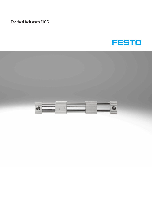
Toothed belt axes ELGGToothed belt axes ELGG CharacteristicsAt a glance• Toothed belt axis with two opposing slides• Optimum price/performance ratio • Ready-to-install unit for quick and easy design• High reliability thanks to tested service life of 2500 km per slide • Motor mounting possible on 4 sideswith identical mounting accessories• Complete kit for a simple andspace-saving solution forend-position sensing• Plain-bearing guide– For small loads– Restricted operating behaviourwith torque load– Guide not backlash-free• Recirculating ball bearing guide– For medium loads– Very good operating behaviourwith torque load– Backlash-free guide (preloadedguide elements)Opposing movement, controlled via a motorApplication examples• Suitable for sorting, separating and spreading• For opening doors• For gripping tasks with small loads• Positioning and handling with low process forces• Centring and aligningCharacteristic values of the axesThe specifications shown in the table are maximum values.The precise values for each of the variants can be found in the relevant datasheet.1) Combined feed force of both slidesH--NoteEngineering softwarePositioningDrives2d Internet: /catalogue/...Subject to change – 2023/0432023/04 – Subject to changed Internet: /catalogue/...Toothed belt axes ELGGCharacteristicsComplete system comprising toothed belt axis, motor, motor controller and motor mounting kitToothed belt axis with recirculating ball bearing guide or plain-bearing guideMotora Page 18Servo motor:EMMT-AS, EMME-AS Stepper motor:EMMS-STH- -NoteA range of specially matchedcomplete solutions is available for the toothed belt axis ELGG and the motors.Servo driveServo drive:CMMT-ASServo drive for extra-low voltage:CMMT-STMotor mounting kita Page 18Kit comprising:• Motor flange • Coupling housing • Coupling •Screws• Slot nuts4d Internet: /catalogue/...Subject to change – 2023/04Toothed belt axes ELGGPeripherals overview12345789106Toothed belt axes ELGG Peripherals overview5 2023/04 – Subject to change d Internet: /catalogue/...Toothed belt axes ELGGType codes6d Internet: /catalogue/...Subject to change – 2023/0472023/04 – Subject to changed Internet: /catalogue/...Toothed belt axes ELGGData sheet-N- Size 35 ... 55-T-Stroke length 50 ... 1200 mm-É-5550 ... 90050 ... 12001)3500.5527.91) The maximum stroke is 1190 mm in combination with extended slide 2) Combined feed force of both slides3)The max. acceleration is dependent on the moving mass, the driving torque and the max. feed force1) Including 2 slides, without central supportToothed belt axes ELGGData sheetIncluding 2 slides, without central support1)J A = J O + K x J W + J S x working stroke [m] + J L x m payload [kg]K = Number of additional slides The mass moment of inertia J A of theentire axis is calculated as follows:8d Internet: /catalogue/...Subject to change – 2023/0492023/04 – Subject to changed Internet: /catalogue/...Toothed belt axes ELGGData sheetMaterialsSectional view12345610d Internet: /catalogue/...Subject to change – 2023/04Toothed belt axes ELGGData sheetCharacteristic load valuesThe indicated forces and torques refer to the centre of the guide. The point of ap-plication of force is the point where the centre of the guide and the longitudinal centre of the slide intersect.These values must not be exceeded during dynamic operation. Special attention must be paid to the deceleration phase.Without central supportWith central supportIf the axis is subjected to two or more of the indicated forces and torques simultaneously, the following equation must be satisfied in addition to the indicated maximum loads:Without central supportCalculating the load comparison factor:F 1/M 1 dynamic values F 2/M 2 dynamic values F 3/M 3maximum valuesWith central supportCalculating the load comparison factor:F 1/M 1dynamic values F 2/M 2 dynamic values F 3/M 3maximum valuesff vv =|FF yy 1+FF yy2|FF yy3+|FF zz1+FF zz2|FF zz3+|MM xx1+MM xx2|MM xx3+|MM yy1+MM yy2|MM yy3+|MM zz1+MM zz2|MM zz3≤1ff vv =|FF yy 1|FF yy3+|FF zz1|FF zz3+|MM xx1|MM xx3+|MM yy1|MM yy3+|MM zz1|MM zz3≤1ff vv =|FF yy 2|FF yy3+|FF zz2|FF zz3+|MM xx2|MM xx3+|MM yy2|MM yy3+|MM zz2|MM zz3≤1Service lifeThe service life of the guide depends on the load. To provide a rough indication of the service life of the guide, the graph below plots the load comparison factor f v against the service life.These values are only theoretical. You must consult your local contact person at Festo for load comparison factors f v greater than 1.5.Load comparison factor f v as a function of service lifel [km]f v2525025002500000.511.522.533.544.5Example:A user wants to move an X kg load. Using the formula a page 10 gives a value of 1.5 for the load comparison factor f v . According to the graph, the guide would have a service life of approx. 750 km. Reducing the acceleration reduces the Mz and My values. A load comparison factor of 1 now gives a service life of 2500 km.H- -NoteEngineering software PositioningDrives m [kg]a [m /s 2]51015202530010********Horizontal VerticalH- -NoteFor the plain-bearing guide (GF) it is recommended to reduce the ac-celeration to minimise overswings and increase positioning accuracy.M [Nm]F [N ]12345050100150200250300350Velocity v as a function of rotational speed nN [1/min]V [m /s ]5001000150020002500300035000123ELGR-TB-35ELGR-TB-45ELGR-TB-55Minimum nominal strokeWith standard slide or long slide L with additional slide ZBStroke reserveL18 = Nominal stroke L19 =Stroke reserve• The stroke reserve is a safety distance from the mechanical end position and is not used in normal operation • The sum of the nominal stroke and 2x stroke reserve must not exceed the maximum permissible working stroke per slide• The stroke reserve length can be freely selected• The stroke reserve is defined via the "stroke reserve" characteristic in the modular product system.Example:Type ELGG-TB-45-500-20H-...Nominal stroke= 500 mm 2x stroke reserve = 40 mm Working stroke per slide = 540 mm (540 mm = 500 mm + 2x 20 mm)Working stroke reductionWith standard slide or long slide L with additional slide ZBL7 = Slide lengthL16 = Distance between the two slidesL17 =Additional slide length• For a toothed belt axis with addi-tional slide, the working stroke is re-duced by the length of the addition-al slide and the distance between the two slides• If the variant long slide L is ordered, the additional slide is not extendedExample:Type ELGG-TB-35-500-...-ZR Working stroke = 500 mmL16= 10 mm L7= 146 mm L17 = 76 mmWorking stroke per slide withadditional slide= 414 mm(500 mm – 10 mm – 76 mm)2nd moments of areaRecommended deflection limitsAdherence to a maximum deflection of 0.5 mm is recommended so as not to impair the functionality of the axes. Greater deformation can result in increased friction, greater wear and reduced service life.Orientation guideO topU bottomR rightL leftV frontH rearAccessoriesNCd Page 23MANMSA, SBSA, SBEAMotorsd Page 18Axial kitd Page 18[1] -... The sum of nominal stroke and 2x stroke reserve must not exceed the maximum stroke length.[2] ZB Working stroke reduction a page 13[3] M With size 35 and stroke > 350 mm, size 45 and stroke > 450 mm,size 55 and stroke > 700 mm, the toothed belt axis is always supplied with central support M.-NoteH-Depending on the combination of motor and drive, it may not be possible to reach the maximum feed force of the drive.1) The input torque must not exceed the max. permissible transferable torque of the axial kit.1) The input torque must not exceed the max. permissible transferable torque of the axial kit.1) The input torque must not exceed the max. permissible transferable torque of the axial kit.Toothed belt axes ELGG Accessories21 2023/04 – Subject to change d Internet: /catalogue/...Toothed belt axes ELGG AccessoriesProfile mounting MUE (order code MA)Material:Anodised aluminiumRoHS-compliantH--NoteThe central support can also beattached using the profile mounting.Sensor bracket EAPM-...-SHS , switch lug EAPM-...-SLS (order code SA/SB)Material:Switch lug: galvanised steelSensor bracket: anodised wroughtaluminium alloyRoHS-compliantH--NoteThe sensor bracket can also bemounted on the central support.EAPM-L4-SHSEAPM-L4-SHS22d Internet: /catalogue/...Subject to change – 2023/04Toothed belt axes ELGG AccessoriesAlternative interface(order code EA)1) Packaging unit2) 4 centring sleeves included in the scope of delivery of the axis23 2023/04 – Subject to change d Internet: /catalogue/...Toothed belt axes ELGGAccessories24d Internet: /catalogue/...Subject to change – 2023/04Festo - Your Partner in AutomationConnect with us/socialmedia 1Festo Inc.2Festo Pneumatic 3Festo Corporation 4Regional Service Center 5300 Explorer DriveMississauga, ON L4W 5G4CanadaAv. Ceylán 3,Col. Tequesquináhuac 54020 Tlalnepantla, Estado de México1377 Motor Parkway Suite 310Islandia, NY 117497777 Columbia Road Mason, OH 45040Festo Customer Interaction CenterTel:187****3786Fax:187****3786Email:*****************************Multinational Contact Center 01 800 337 8669***********************Festo Customer Interaction Center180****3786180****3786*****************************S u b j e c t t o c h a n g e。
SI-30 chinese manual

! 注意!!!
本中文操作说明书是由英文原版翻译而成,仅供用户参考,详情请参 阅随机英文原版说明书;
因生产商对设备更改而使说明书与实际操作造成的差异,恕不另行通 知。
பைடு நூலகம்广州市一帆船务设备有限公司
2
自动识别系统 SI-30 中文操作说明书
目
录
1. 缩写.....................................................................................................................................5 2. 概要.....................................................................................................................................5
2.1.1. 主要信息 ........................................................................................
直线电机驱动器说明书

电 话 (Tel) :(86)(755)26982158
传真(Fax):(86)(755)26982786 邮政编码(Postcode):518057
电子邮箱(E-mail)::sales.pme@
网址(Website): /
1/3 7
深圳市大族精密机电有限公司 Shenzhen Han’s Precision Mechatronics Co. ,Ltd.
目录
第 1 章 安全注意事项...........................................................................................................3
第 4 章 软件操作 ......................................................................................12
4.1 计算机要求说明 .....................................................................................................................12 4.2 软件安装 .................................................................................................................................12 4.3 软件界面操作 ........................................................................................................................12 4.4 详细调试说明 .........................................................................................................................15
Parker LCB系列线性电机说明书

L C B S e r i e sContentsOverview....................................................................................................70Specifications............................................................................................73T echnical.Data .LCB040.Loading/Wear........................................................................74.LCB060.Loading/Wear........................................................................76.Drive.Torque.Requirements................................................................78.Deflection............................................................................................79Dimensions................................................................................................80Options......................................................................................................82Accessories .Sliding.Blocks......................................................................................83.External.Bumpers...............................................................................83.Electrical.Limit.Switches.....................................................................84.Clamping.Profiles................................................................................85.T rmation .Basic.Unit............................................................................................87.Intermediate.Drive.Shaft.....................................................................88Application.Fax.Form (89)LCB Compact Linear ActuatorParker.Hannifin.CorporationActuator.DivisionWadsworth,A Phone:.1-866-P ARK-ACTemail:*************************website:/actuatorL C B S e r i e s70Actuator Division1-866-PARK-ACTThe LCB SeriesLCB Markets and ApplicationsThe.LCB.series.rodless.actuator.has.proven.to.be.a.robust.and.reliable.solution.for.numerous.motion.control.appli-cations.across.many.markets.and.industries...Listed.below.are.some.examples.of.where.and.how.the.LCB.series.rodless.actuator.has.been.successfully.applied..............The.LCB.series.of.linear.actuators.incorporates.a.low.friction,.dry.running.sliding.bearing.carriage.that.provides.long.and.reliable.travel.life.even.at.100%.duty.cycle...The.low.mass.of.the.carriage.and.steel.reinforced.timing.belt.design.allows.for.very.high.acceleration.and.velocity...With.accelerations.exceeding.2G’s.and.speeds.up.to.8.m/s,parable.throughput.to.linear.motors.at.a.fraction.of.the.cost..The.simple,bined.with.Parker.motors.and.controls,.the.LCB.offers.a.fully.programmable,.high.performance.solution.at.a.great.value.......The LCB design means . . . .•.Increased.throughput.–.100%.Duty.Cycle.Operation•.High.acceleration.(20.m/s 2).and.velocity.(8.m/s)•.T wo.profile.sizes.(LCB040.&.LCB060).•.Dry.running,.low.friction.bearings.provide.long,.reliable.life•pared.to.other.bearing.type•.High.static.load.capacity.-.Well.suited.to.withstand.pressing..forces.at.standstill.......•.Short,.medium,.and.long.carriages.available.to.optimize..moment.load.capacity.L C B S e r i e s71Actuator Division1-866-PARK-ACT1 Guide The.external.sliding.guide.is.incorpo-rated.as.part.of.the.aluminum.profile..It.is.unnecessary.to.adjust.two.separate.guiding.rails..The.guide.is.maintenance.free.with.integrated.dry-film.lubricant.2 Sliding CarriageThe.sliding.carriage.is.available.in.three.lengths..With.a.longer.sliding.carriage,.there.is.greater.distance.between.the.sliding.blocks..This.improves.the.load.capacity.with.respect.to.yaw.and.pitch.moments.3 Sliding BlocksLow.friction.sliding.blocks.provide.smooth.motion.throughout.travel..Sliding.blocks.can.be.easily.changed.within.2.minutes.without.detensioning.the.timing.belt.4 Spacer PlatesThe.timing.belt.of.the.LCB040.is.ten-sioned.directly.at.the.sliding.carriage.by.means.of.spacer.plates.5 Tensioning StationOn.the.LCB060,.the.timing.belt.is.tensioned.via.tensioning.screws.at.the.tensioning.station.6 ProfileThe.profile.is.available.in.two.sizes.and.resistant.to.flexing..The.closed.profile.provides.high.torsional.stiffness..Profiles.are.dirt.tolerant,pact.design.means.minimum.installation.space.is.required.Construction7 Timing Belt DriveHigh.stiffness.and.accuracy.are.provided.by.the.generously-dimensioned.timing.belt.8 Drive Options•..Linear.actuator.with.free.shaft.end.•..Coupling.(9).&.gearbox.•..Coupling,.gearbox.&.motor.•..Coupling.&.direct.drive.motor.(10).LCB040LCB06072Actuator Division1-866-PARK-ACTDual Axis ActuatorsFor.a.dual-axis.actuator.with.the.driveon.the.right.side,.you.need.two.LCB.basic.units:.1).the.right.unit.with.drive.option.RDN.and.2).the.left.unit.with.drive.option.RSN.For.a.dual-axis.actuator,.two.LCB.basic.units.and.a.shaft.corresponding.to.the.desired.center-distance.are.required..Parker.will.deliver.the.two.basic.units.(with.mounted.couplings.–.if.this.was.ordered).and.a.separate.shaft.kit..See.page.88.for.shaft.kit.ordering.Center Distance(from.center.line.to.center.line)For.a.dual-axis.actuator.with.the.drive.on.the.left.side,.you.need.two.LCB.basic.units:.1).the.left.unit.with.drive.option.LDN.and.2).the.right.unit.with.drive.option.LSN.L C B S e r i e s73Actuator Division1-866-PARK-ACT1...Repeatability.is.unidirectional,.achieved.under.ideal.conditions.and.slow.speeds....Actual.repeatability.may.vary.with.the.application..Operating Temperature Range0°.to.60°C.(32°.to.140°F).Available Stroke LengthsLCB Specifications74Actuator Division1-866-PARK-ACTLCB040 Life vs. LoadThe.diagrams.are.valid.solely.for.guidance.and.under.ideal.operating.conditions..The.diagrams.are.based.on.a.trapezoidal.motion.sequence.with.3.identically.long.sections.for.acceleration,.constant.travel.and.deceleration.The.diagrams.are.based.on.defined.payloads.of.1.kg..Shown.are.the.respective.mass.centroids.with.their.typical.load.arms.Actuator LifeNaturally,.the.sliding.guiding.has.already.a.slight.play.under.new.condition,.so.that.the.guiding.does.not.jam.and.the.slid-ing.carriage.moves.smoothly..The.play.is.measured.as.a.gap.for.each.slide.and.is.approx..0.1.to.0.2mm.in.normal.direction.and.at.the.sides.During.the.operation,.the.play.increases.according.to.the.loads.shown.in.the.diagrams.If.a.certain.state.of.wear.is.reached.(the.wear.limit..is.0.5mm.for.the.LCB040),.the.slides.can.be.exchanged.easily.within.a.few.minutes..After.the.exchange,ing the DiagramsLife.is.shown.for.each.length.of.carriage:.short.(S),.medium.(M).and.long.(L)..The.diagrams.can.be.interpolated.with.respect.to.lifetime.and.extrapolated.with.respect.to.load..(for.example:.halved.operational.performance.results.in.halved.wear,eage.in.km).T r a v e l (1000k m )Acceleration,m/s 2T r a v e l (1000k m )Acceleration (m/s 2)T r a v e l (1000k m )Acceleration (m/s 2)T r a v e l (1000k m )Acceleration (m/s 2)L C B S e r i e s75Actuator Division1-866-PARK-ACTT r a v e l (1000k m )Acceleration (m/s 2)T r a v e l (1000k m )Acceleration (m/s 2)T r a v e l (1000k m )Acceleration (m/s 2)T r a v e l (1000k m )Acceleration (m/s2)T r a v e l (1000k m )Acceleration (m/s 2)24681012141618T r a v e l (1000k m )Acceleration (m/s 2)76Actuator Division1-866-PARK-ACTLCB060 Life vs. LoadThe.diagrams.are.valid.solely.for.guidance.and.under.ideal.operating.conditions..The.diagrams.are.based.on.a.trapezoidal.motion.sequence.with.3.identically.long.sections.for.acceleration,.constant.travel.and.deceleration.The.diagrams.are.based.on.defined.payloads.of.5.kgs.Shown.are.the.respective.mass.centroids.with.their.typical.load.arms.Actuator LifeNaturally,.the.sliding.guiding.has.already.a.slight.play.under.new.condition,.so.that.the.guiding.does.not.jam.and.the.slid-ing.carriage.moves.smoothly..The.play.is.measured.as.a.gap.for.each.slide.and.is.approx..0.1.to.0.2mm.in.normal.direction.and.at.the.sides.During.the.operation,.the.play.increases.according.to.the.loads.shown.in.the.diagrams.If.a.certain.state.of.wear.is.reached,stest.however.at.the.wear.limit.(1.0mm.for.the.LCB060),.the.slides.can.be.exchanged.easily.within.a.few.minutes..After.the.exchange,ing the DiagramsLife.is.shown.for.each.length.of.carriage:.short.(S),.medium.(M).and.long.(L)..The.diagrams.can.be.interpolated.with.respect.to.lifetime.and.extrapolated.with.respect.to.load..(for.example:.halved.operational.performance.results.in.halved.wear,eage.in.km).T r a v e l (1000k m )Acceleration (m/s 2)T r a v e l (1000k m )Acceleration (m/s 2)T r a v e l (1000k m )Acceleration (m/s 2)T r a v e l (1000k m )Acceleration (m/s 2)78Actuator Division1-866-PARK-ACTLCB Drive Torque RequirementsThe.graphs.include.both.acceleration.and.friction.forces.(2.2)(4.4)(6.6)(8.8)(11.0)(13.2)Payload,kg (lb)D r i v i n g T o r q u e ,N m (l b -i n)(2.2)(4.4)(6.6)(8.8)(11.0)(13.2)Payload,kg (lb)3.2(28.4)2.8(24.8)2.4(21.3)2.0(17.8)1.6(14.2)1.2(10.6)0.8(7.1)0.4(3.5)0.0D r i v i n g T o r q u e ,N m (l b -i n)14(124)12(10710(89)6(53)4(36)2(18)0.0D r i v i n g T o r q u e ,N m (l b -i n )8(71)(11)(22)(33)(44)(55)(66)Payload,kg (lb)(11)(22)(33)(44)(55)(66)Payload,kg (lb)14(124)12(10710(89)6(53)4(36)2(18)0.0D r i v i n g T o r q u e ,N m (l b -i n )8(71)LCB040 – Horizontal Mounting PositionLCB040 – Vertical Mounting PositionLCB060 – Horizontal Mounting PositionLCB060 – Vertical Mounting PositionLocation of Mass Barycenter or Point of Force Application2:1.RuleDrawing.shows.example.of.the.pitch.moment..Also.valid.for.roll.and.yaw.moments.respectively.I L .=.Load.lever I T .=.Support.LeverL C B S e r i e sDeflectionGraphs.show.deflection.vs..distance.between.mountings.and.load.1.0(0.225)10.0(2.25)100.0(22.5)1000.0(225)10000.02250Distance between Mountings (SA),mmF o r c e F n ,N (l b )0.1(0.0225)Distance between Mountings (SA),mm1.0(0.225)10.0(2.25)100.0(22.5)1000.0(225)10000.02250F o r c e F n ,N (l b )0.1(0.0225)LCB040LCB060LCB040 Basic DimensionsShortcarriageSMediumcarriageMSectionA-ADetailY(enlarged)x deDetailX(enlarged)NecessforchatheplasDrivestationLSDrivestationRSDrivestationLD/RDL C B S e r i e sLCB060 Basic DimensionsD r i v e s t a t i o n L SD r i v e s t a t i o n R SD r i v e s t a t i o n L D /R DDrive Orientation (R, L)Right/left.indication.looking.from.load.attachment.plate.to.drive.module.Drive Shaft (S, D)Double.shaft.(D).models.have.an.additional.shaft.on.the.op-ed.to.attach.the.shaft.for.dual-axis.actuators.With Free Drive ShaftThe.threads.to.attach.the.coupling.are.on.the.side.defined.under."Drive.Orientation". With Attached Coupling KitThe.coupling.kit.is.always.mounted.in.the.factory..Carriage Length (S, M, L)All.sliding.carriages.have.4.sliding.blocks..On.a.longer. sliding.carriage,.the.load.bearing.capacity.for.yaw.and.pitch.moments.(My.and.Mz).is.greater.L C B S e r i e sSliding BlocksThe.sliding.block.is.a.wearing.part..Four.(4).pieces.are.required.per.linear.actuator.External BumpersA-AElectrical Limit Switches1.PNP.normally.closed.contact2.Load3.LoadLCB040LCB060L C B S e r i e sClamping Profilesed.in.conjunction.with.the.standard.load.attachment.plate.to.rapidly.install.and.attach.various.conbinations.of.linear.actuators..T ed.in.the.range.of.the.drive.or.of.the.clamping.station.LCB040LCB060T-Nuts and Boltsponents. to.the.T-slots.of.the.profile.T-NutsT-Slot Bolts and NutsDIN.562DIN.934DIN.787L C B S e r i e s1.Not.all.motor/binations..bined.with.Gearbox.Option.“0”.(no.gearbox),.this.option.is.direct.mount.with.no.flange.included.patibility.and.coding.4.Stroke.is.measured.bumper.to.bumper.Maximum Standard Stroke LengthConnecting ShaftDual-Axis Actuator DimensionsLCB040LCB060L C B S e r i e s89Actuator Division1-866-PARK-ACTFaxcompletedformto(330)*****************************************Contact Information:Name.______________________________________.Phone.__________________________Company.___________________________________.email.___________________________City,.State,.Zip._________________________________________________________________Application SketchNOTES:Please.include.the.critical.dimensions.in.your.sketch.In.order.to.achieve.the.best.solution,.it.is.important.that.you.provide.as.much.in-formation.as.possible.Motion ProfileMoves Distance (Stroke)Time Thrust or Load DwellFirst.Motion Second.Motion Third.Motion Fourth.MotionMoment LoadingX.distance._______Y.distance._______Z.distance._______Environmental Requirements1. Operating Temperature .Max._______.....Min._______2. Comtanimation .(check.one)..Particle.....Liquid.Type:._______________________3. Special Considerations .________________.._____________________________________.._____________________________________Application Requirements:1. Overall Stroke .(add.25mm.per.end.minimum).____________2. Cylinder Orientation .(check.one)...Horizontal............Inverted.......Side.Mount....Vertical...Angle:..Degree._________3. Load/Tooling Weight __________________________4. Repeatability Requirements .____________________...Unidirectional.......Bidirectional5. Is the load externally guided?.(check.one)...Y es.......No.If.yes,.how?._________________________________6. Is the actuator body supported?.(check.one)..Y es.......No.If.yes,.how?._________________________________7. Life Requirements .(cycles,.distance.or.years).Hours.per.day._________....Days.per.year._________8. Special Considerations .______________________________..___________________________________________________..___________________________________________________..___________________________________________________Please attach another sheet if more room is needed.90Actuator Division1-866-PARK-ACTMotor, Drive and Control Options:1. Motor Options .(check.all.that.apply)...Stepper.............Servo...Parker.Supplied.........Customer.Supplied.(provide.print).2. Other Options .(check.one)...Drive............Drive/Controller.......Controller3. Available Line Voltage .____________4. Switches/Sensors .(quantity).End.of.Travel._______..........Home._________5. Brake Option .(check.one)...Motor........6. Special Options ._______________________________________.____________________________________________________.____________________________________________________.____________________________________________________.____________________________________________________Actuator Type and Mounting1. Drive Orientation .(check.one)..2. Drive Shaft .(check.one)...Double.Shaft3. Carriage Style (check one): See ....Medium.Carriage.....Long.Carriage..。
SIEMENS SINUMERIK 802S base line 说明书

安装调试技术手册机床生产厂商文献适用于控制系统软件版本SINUMERIK 802S base line 4.22007年04月SINUMERIK文献版本说明以下是当前版本及以前各版本的简要说明。
每个版本的状态由“附注”栏中的代码指明。
在“附注”栏中的状态码分别表示:A ... ... 新文件B ... ... 没有改动,但以新的订货号重印C ... ... 有改动,并重新发行版本订货号附注1999.026FC5597-2AA00-0RP1 A2002.016FC5597-2AA00-0RP2 C2003.086FC5597-4AA01-3RP0 C2005.126FC5597-4AA01-3RP0 C2006.106FC5597-4AA01-0RP1 C2007.046FC5597-4AA01-0RP1 C注册商标SIMATIC®,SIMATIC HMI®,SIMATIC NET®,SIMODRIVE ®,SINUMERIK®,和SIMOTION®均为西门子公司的注册商标。
本文件中的其他名称也可能是商标,任何第三人擅自使用此商标将会侵犯注册商标所有人的权利。
©西门子股份公司版权所有2007年没有明确的书面许可,任何人不得翻印、传播和使用本文献及其中的内容,违者将负责赔偿损失。
西门子公司享有所有版权及相关权利,包括专利权或实用新型的申请注册权。
责任免除经过审查,本文献的内容与其描述的软件和硬件相符合。
但是仍可能存在一些差异。
因此我们不能保证它们完全一致。
我们会定期审查本文献,并在下一个版本中作出必要的修改。
欢迎提出改进意见和建议。
© Siemens AG, 2007如有技术改动,恕不提前通知。
Siemens-Aktiengesellschaft. SINUMERIK 802S/C base line ®SINUMERIK 802S base lineI 安装调试 安全信息 该手册中包含一些安全信息说明,在操作时必须遵照执行,以确保人身安全,保护产品和连接设备不受损坏。