2014年全国固定资产投资(不含农户)增长15.7%
2014年 主流电脑游戏配置
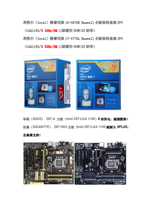
英特尔(Intel)酷睿四核i5-4670K Haswell全新架构盒装CPU (LGA1150/3.4GHz/6M三级缓存/84W/22纳米)英特尔(Intel)酷睿四核i7-4770k Haswell全新架构盒装CPU (LGA1150/3.5GHz/8M三级缓存/84W/22纳米)华硕(ASUS)Z87-A 主板(Intel Z87/LGA 1150)8相供电,超强散热!技嘉(GIGABYTE)Z87-HD3主板(Intel Z87/LGA 1150)超耐久4PLUS,全高清支持!航嘉(HuntKey)多核WD600 电源(额定功率600W/85%高效率/宽幅电压/超长背部走线)鑫谷(Segotep)额定500W GP600G黑金电源(80PLUS金牌/效率达87%以上,支持背线/超静音温控映众(Inno3D)GTX770 冰龙1098/7010MHz 2GB/256Bit GDDR5 PCI-E 显卡微星(MSI)N770 TF 2GD5/OC 1137(Boost Clock1198) /7010MHz 2048MB/256bit GDDR5 PCI-E显卡,10公分刀锋扇叶,五热管三星(SAMSUNG) 840Pro系列128G 2.5英寸SATA-3固态硬盘(MZ-7PD128BW)英特尔(Intel)530 系列固态硬盘120G 简包SATA3接口SSDSC2BW120A401九州风神(DEEPCOOL)玄冰400 多平台CPU散热器12025发光风扇四热管可调速超频三(PCCOOLER) 红海-至尊版全铜材质90mm智能温控风扇全平台CPU散热器恩杰(NZXT)PHANTOM 410 小幻影中塔游戏机箱红(原生USB3.0/背部走线/自带三个静音风扇/全兼容SSD)芝奇(G.SKILL)RipjawsX DDR3 2133 8G(4G×2条)台式机内存(F3-17000CL11D-8GBXL)海盗船(CORSAIR)复仇者DDR3 2133 8GB(2x4GB)台式机内存(CMZ8GX3M2A2133C11R)惠科(HKC) T7000+ 27英寸2560*1440顶级H-IPS屏LED背光宽屏液晶显示器点距0.233。
Moxa UC-7112 Plus 7112 7110 快速安装指南(第五版,2014年1月)说明书

– 1 –– 2 – – 3 –P/N: 1802071100114UC-7112 Plus/7112/7110 Quick Installation GuideFifth Edition, January 20141. OverviewThe Moxa UC-7112 Plus, UC-7112, and UC-7110 are mini size RISC-based ready-to-run embedded computers that feature dual 10/100 Mbps Ethernet ports and two RS-232/422/485 serial ports in a built-in µClinux ARM9 box. In addition, the UC-7112 provides an internal SD socket for storage expansion, to offer highperformance communication and unlimited storage in a super compact, palm-size box. The UC-7112 Plus, UC-7112, andUC-7110 are the right solutions for embedded applications that use a lot of memory, but that must be housed in a small physical space without sacrificing performance.2. Package ChecklistBefore installing the UC-7112 Plus/7112/7110, verify that the package contains the following items: • 1 UC-7112 Plus, UC-7112,or UC-7110 • Quick Installation Guide • Document & Software CD• Cross-over Ethernet cable: RJ45 to RJ45, 100 cm • Console port cable: CBL-4PINDB9F-100(4-pin header to female DB9 cable, 100 cm) • Universal Power Adaptor•Product Warranty StatementOptional Accessories •DK-35ADIN-Rail Mounting Kit (35 mm)NOTE: Please notify your sales representative if any of the above items are missing or damaged.3. Hardware IntroductionLED IndicatorsThe following LED indicators are located on the top panel of the UC-7112 Plus/7112/7110.UC-7112 Plus/7112/7110 Top ViewThe top view of the UC-7112 is shown in the following figure. The UC-7112 Plus and UC-7110 look similar, except that the UC-7110 does not have an internal SD slot.UC-7112 Plus/7112/7110 DimensionsThe dimensions of the three products are shown in the following figure.4. Hardware Installation ProcedureSTEP 1: Remove the UC from the box and attach the poweradaptor.STEP 2: Connect the UC’s serial console cable to your PC’s RS-232COM port for initial setup through the console terminal.STEP 3: Connect the UC to a network. Use a standardstraight-through Ethernet cable to connect to a hub or switch. When setting up or testing the UC, you might find it convenient to connect directly to your computer’s Ethernet port. In this case, use a cross-over Ethernet cable.STEP 4: Install Secure Digital (SD) Memory Card (UC-7112and UC-7112 Plus only)To install an additional SD card, you must first remove the UC-7112’s outer cover to access the slot. The internal SD socket is located at the back side of the UC-7112 on the bottom board; you can find the SD socket on the right, a little lower than the cover screw. Plug the SD card directly into the socket. To remove the card, press it in first, and then remove your finger. The card will pop out enough to allow you to remove it.STEP 5: Placement OptionsIn addition to placing the UC on a desktop or other horizontal surface, you may also make use of the DIN-Rail or Wall Mount options, as illustrated here.Wall MountDIN-Rail5. Software Installation ProcedureSTEP 1: Insert the UC’s CD-ROM into your Windows or Linux PC,and then use Acrobat Reader to read the UC-7112/7110 Series User’s Manual.STEP 2: Install the UC’s tool chain, which is on the CD-ROM. Thetool chain consists of the following components:1. UC Finder: Broadcast search for the UC’s IP address on your LAN. The UC supports both Windows and Linux environments.2. Cross Compiler: Arm-elf-gcc for µClinux platforms (UC-7112/7110), and Arm-linux-gcc for embedded Linux platform (UC-7112 Plus). Both options are C/C++ PC cross compilers, which are gcc compilers that run on an x86 PC, but create an execution file for Arm-based platforms, such as the UC-7112/7110.– 4 – – 5 – – 6 –/supportThe Americas: +1-714-528-6777 (toll-free: 1-888-669-2872)Europe: +49-89-3 70 03 99-0 Asia-Pacific: +886-2-8919-1230China: +86-21-5258-9955 (toll-free: 800-820-5036)2014 Moxa Inc. All rights reserved.3. GNU C Library: The GNU standard POSIX C Library is supported for both the UC-7112 Plus’s Linux platform, and the UC-7112/7110’s uClinux platform. Glibc is for Linux and µClibc is for uClinux, which is an abbreviation for “microcontroller C library.” µClibc was created to support µClinux, a Linux port for MMU-lessmicrocontrollers, such as the ARM9 installed in the UC-7112/7110. For more information, visit .STEP 3: Edit source code on a Linux PC.STEP 4: Use the Cross Compiler to compile the source code, andthen use FTP to download the program to the UC.STEP 5: Run your program.6. System Commandsbusybox: Linux / µClinux normal command utility collection File manager cpcopy file ls list filelnmake symbolic link filemount mount and check file system rmdelete filechmod change file owner & group & user chown change file owner chgrp change file groupsync sync file system; save system file buffer to hardware mv move filepwd display active file directly df list active file system space du estimate file space usage mkdir make new directory rmdir delete directoryhead print the first 10 lines of each file to standard outputtail print the last 10 lines of each file to standard outputtouch update the access and modification times of each file to the current timeEditor vi text editorcat dump file contextgrep print lines matching a patterncut remove sections from each line of files find search for files in a directory hierarchy more dump file by one page test test if file exists or not echo echo stringProcess kill kill processkillall kill process by name ps report process statussleep suspend command on time (seconds)Networkping ping to test network route routing table manager netstat display network status ifconfig set network IP address tftp tftp protocoltelnet user interface to TELNET protocol ftpfile transfer protocoliptables-restore restore iptables configuration file to network iptablesiptables commandiptables-save save recent iptables configuration to file Otherdmesg dump kernel log message stty set serial portmknod make device nodefree display system memory usagedate print or set the system date and timeenv run a program in a modified environment clear clear the terminal screenreboot reboot / power off/on the server halthalt the servergzip, gunzip, zcatcompress or expand files hostname show system’s host name tartar archiving utilityMoxa special utilities cat /etc/version show user directory version upramdisk mount ramdisk downramdisk unmount ramdisk kversion show kernel versionfsversion show the root file system (firmware) version setinterface set UART interfaces program7. Pin AssignmentsDB9 MaleSerial Console Port*NC=Not Connected8. Environmental SpecificationsPower requirements 12 to 48 VDCOperating temp.-10 to 60°C (14 to 140°F), 5 to 95% RH Storage Temperature -20 to 80°C (-4 to 176°F), 5 to 95% RH Serial protection 15 KV ESD for serial port Magnetic isolation 1.5 KV for EthernetRegulatory approvals FCC Class A, CE Class A, UL, cUL, TÜV Warranty 5 years。
TopSolid 2014 V6.15安装说明,乱码 翻译,已测试
*Установите TopSolid.
【by Jackwangqf】Install TopSolid
*Выберете при установке опцию 'Floating license' > 'Client AND License Server' > напишите имя вашего компьютера и напишите 255
*Создайте системную перемененную 'LSFORCEHOST' и запишите в её значение имя вашего компьютера
【by Jackwangqf】:Create a system peremenennuyu 'LSFORCEHOST' and write down its value in the name of your computer.
DVD1:\Redist\Sentinel RMS License Manager\Tools
Развертите группу Subnet Servers, щелкните правой кнопкой на имени, соответствующем вашему компьютеру, и выберете:
*Установите 'Sentinel RMS License Manager 8.5.3.msi' из папки
DVD1:\Redist\Sentinel RMS License Manager
【by Jackwangqf】:Install the program 'Sentinel RMS License Manager 8.5.3.msi' in folder
Shimadzu GC-2014C184-E014F 产品说明书.pdf_1718759513.25

GC-2014Big Performance & Small Space GC-2014Improved design and innovative technology for all of our injectors, detectors and fl ow controllers equal or surpass our GC-2010 the high-end technology leader.High PerformanceSuperior PerformanceLarge LCD, all digital gases control and auto-diagnostics inherited from the GC-2010 – “The Most advanced, easy-to-use interface”Easy OperationExcellent User InterfaceUse any column types for any analysis. Packed or capillary columns give you the freedom to choose the best technique for your measurement. Fully integrated multiple valve systems are made simple for optimum performance for SystemGC custom GC products.FlexibilityExpandability for Every SituationSimple nozzle replacement supports both capillary and packed columns.Our New FPD is used for all columnsDetectorsHolophotal Flame Photometric DetectorPhotomultiplierFilter Lens Nozzle The detectors have been completely redesigned, incorporating the GC-2010 detector designs for capillary analyses and the GC-14 detector designs for packed columns. This TCD-2014 unit is ideal for packed column measurements employing the semi-diffusion cell designInjection unitswith unsurpassed accuracyThe design of the SPL-2014 capillary column sample injection unit is based on the GC-2010 technology.This accuracy was unattainable with previous models.The packed column sample injection unit employs the proven design of the GC-14 injection unit.Easier to understand, simpler operationLarge display, help functions and pop-up screens Loaded with productivity-enhancing functionsEasy OperationA large LCD displays chromatograms and method parameters.This is a great improvement for Chromatopacs systems that do not have these real time displays.Graphical user interface enables quick setting of all analytical conditions.The built-in Help function almost eliminates need for familiarization training.Large displayshows most analysis details at a glance,ideal for Chromatopac users.Graphical popup screen that clearly indicates thepolarity so manual injection errors are prevented when using the dual packed column system.Polarity display prevents injection errorsEasy-to-understand Pop-up ScreensChromatogram display Graphical U/IBuilt-in Help FunctionLarge Display6Self-diagnosticsUnit control check Hardware diagnosis Save and check diagnosis logGC-2014250mmGC-14230mmSolenoid valve unitManual fl ow controllersAFCSpeci fi cationsDetectorsTemperature range Temperature settingNo. of units installed simultaneously Detector type 400°C max. (FID, TCD, FTD) 350°C max. (ECD, FPD) 1°C stepsUp to 4 units (restricted depending on detector type) FID, TCD, ECD, FPD, FTD for capillary/packedDual fl ow rate differential system400°C max.3pgC/s (dodecane)107Quartz glass Standard: for packed, Option: for capillaryFlame Ionization Detector (FID) SystemTemperature rangeMinimum detected quantityDynamic rangeNozzleThermal Conductivity Detector (TCD)System Temperature range Dynamic range Sensitivity Dual fl ow rate differential system400°C max.10540,000mV · mL/mg (built-in pre-ampli fi er, with 10 × ampli fi cation)Electron Capture Detector (ECD)SystemTemperature range Minimum detected quantity Dynamic range Fixed current system using 63Ni370MBq radiation source 400°C max.0.1pg/s (γ-BHC)104Flame Photometric Detector (FPD)Temperature range Dynamic rangeMinimum detected quantity 350°C max.P: 104S: 103P: 0.5pgP/s (tributyl phosphate) S: 8pgS/s (dodecane thiol)Flame Thermionic Detector (FTD)Temperature range Dynamic rangeMinimum detected quantity (Two types, one for capillary and one for packed. The speci fi cation are the same.) 400°C max.N: 103P: 103N: 0.4pgN/s (azobenzene)P: 0.05pgP/s (malathion)Display240 × 320 dot graphics display (30 characters × 16 lines)Dimensions, Weight, Power Requirements (GC main unit)Dimensions WeightPower Requirements 400 (W) × 690 (H) × 607 (D) mm48kg (GC-2014AF model)AC100V/120V 230V1800VA (GC-2014AF model) or2600VA (GC-2014AF model), 50/60HzColumn OvenTemperature range DimensionsOven capacity Temperature accuracy Temperature deviation Temperature variation coef fi cient Temperature program steps Programmed rate setting range Total time for all steps Linear heating rangeCooling rateColumns accepted (Ambient + 10°C) ~ 400°C (using liquid CO2 gas*: -50°C ~400°C)250 (W) × 360 (H) × 175 (D) mm15.8LSet value (K) ± 1% (calibration at 0.01°C increments)2°C max. (on 200mm dia. circumference 30mm from rear)0.01°C/°CUp to 20 (cooling program possible)-250°C ~ 250°C/min9999.99 minutes max.30°C/min up to 150°C20°C/min up to 250°C10°C/min up to 380°C7°C/min up to 400°C (at 25°C ambient temperature)300°C ~ 50°C in 6 min max. (at 25°C ambient temperature)Capillary columns: 2Packed columns for GC14B: 4 (Glass columns: 2)Sample Injection UnitTemperature rangeHeating settingsNo. of units installed simultaneously Sample injection unit types Up to 400°C1°C stepsUp to 3 unitsDual packed, single packed, split/splitless, direct, direct (AMC)Carrier Gas Flow Controller For Packed / DualFlow rate setting range Programmable steps Programmed rate setting range Correction function 0 ~ 100mL/min7-400 ~ 400mL/minMaintains column fl ow rate during column oven heatingFor Capillary Split/Splitless, Direct (Split/splitless injection mode)Pressure setting range Programmable steps Programmed rate setting range Split ratio setting rangeTotal fl ow rate setting range Correction function 0 ~ 970kPa7 (pressure-decreasing program possible)-400 ~ 400kPa/min0 ~ 9999.90 ~ 1200mL/minMaintains column average linear velocity during column oven heating (for capillary only)(Pressure mode direct injection)Pressure setting range Programmable steps Programmed rate setting range Correction function 0 ~ 970kPa/min7-400 ~ 400kPa/minMaintains column average linear velocity during column oven heating (for capillary only)(Flow-rate mode direct injection)Flow rate setting range Programmable steps Programmed rate setting range 0 ~ 1200mL/min 7-400 ~ 400mL/minFor Single Packed, Direct (AMC)Flow rate setting range Correction function 0~100mL/minMaintenance column fl ow rate during column oven heating*Optional parts are required to use liquid CO2 gas.。
NSF14中文

元件認證指南目錄飲用水處理系統和元件認證指南章節-----------------------------------------------------------------------------------頁碼序--------------------------------------------------------------------------------------1-4 概況-----------------------------------------------------------------------------------5常見問題-----------------------------------------------------------------------------6-8 NSF標準規定-----------------------------------------------------------------------9-15 認證-----------------------------------------------------------------------------------15-18 與供應商合作-----------------------------------------------------------------------19詞彙表--------------------------------------------------------------------------------20-24 附錄A--------------------------------------------------------------------------------25附錄B--------------------------------------------------------------------------------26附錄C--------------------------------------------------------------------------------27-28 聯絡資訊-----------------------------------------------------------------------------29序NSF International(簡稱NSF)成立於1944年,為一個致力於公共衛生安全以及環境保護的機構。
iTiens PAD 2014 简介

iTiens PAD 2014 系统简介
主界面
左侧桌面 右侧桌面
1、手指触摸屏幕左右划动,切换桌面 2、可以自定义
iTiens 私属定制 五大 应用 游客权限说明
“游客”权限说明:不能访问“天狮阅读” 和“健康时钟”模块 customer 默认“游客”账号 默认“游客”密码
填写验证码
单击“登入”
iTiens 私属定制五大应用 五、健康时钟
人体经络图 重要穴位 指示图 保健器械 菜单栏
iTiens PAD 2014 配件
OTG线 HDMI线
皮套
充电器插头
触屏笔
数据线兼充电线
请以实物为准 针对6月以前所有提前预定用户赠送一付耳机
iTiens PAD 2014
如果您的电视机、投影仪是VGA接口请您自购HDMI母转VGA转换器
HDMI转VGA接口的方法:
HDMI端口
VGA端口
非产品配件
9 8
4 3 2
11 12
7
5 6 1
10
14 13
iTiens 私属定制五大应用 二、天狮阅读
iTiens 私属定制五大应用 三、产品展馆
iTiens 私属定制五大应用 四、视觉天下
iTiens 私属定制五大应用 五、健康时钟
子午流注养生是中医圣贤发现的一 种规律养生法,主张人体中十二条经 脉对应着每日的十二个时辰,由于时 辰在变,因而不同的经脉中的气血在 不同的时辰也有盛有衰。 天狮器械保健以传统中医理论为指 导,遵循阴阳五行生化收藏之变化规 律,以激光,能量因子,电脉冲,音 乐等手法科学保健人体穴位和经络, 对人体进行科学调养,保持生命健康 活力。从而实现未病先防、未老先养 ;天人相应、形神兼具;调整阴阳、 补偏救弊; 动静有常、和谐适度。如 《内经》云:“恬淡虚无,真气从之 ,精神内守,病安从来”。
TDA1547_datasheet

21 AGND L
n.c. 13
20 n.c.
+ OUT R 14
19 + OUT L
– OUT R 15 VSSA 16
18 – OUT L 17 VDDA
MCD294
Fig.1 Pinning diagram.
September 1991
3
Philips Semiconductors
Dual top-performance bitstream DAC
2
Philips Semiconductors
Dual top-performance bitstream DAC
Product specification
TDA1547
handbook, halfpage
DGND 1
VDDD 2
32 VSUB 31 VSSD
IN R 3
30 IN L
n.c. 4
29 n.c.
third-order noise shaper. The excellent performance of the SAA7350 and TDA1547 bitstream conversion system is obtained by separating the noise shaping circuit and the one-bit conversion circuit over two IC's, thereby reducing the crosstalk between the digital and analog parts. The TDA1547 one-bit converter is processed in BIMOS. In the digital logic and drivers bipolar transistors are used to optimize speed and to reduce digital noise generation. In the analog part the bipolar transistors are used to obtain high performance of the operational amplifiers. Special layout precautions have been taken to achieve a high crosstalk immunity. The layout of the TDA1547 has fully separated left and right channels and supply voltage lines between the digital and analog sections.
VFA Series Butterfly Valves Instruction Manual
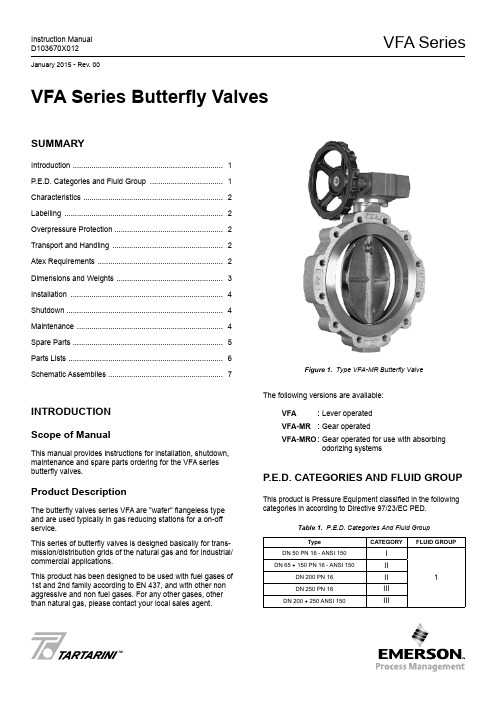
VFA SeriesInstruction Manual D103670X012January 2015 - Rev. 00TMVFA Series Butterfly ValvesSummaryIntroduction ........................................................................ 1P .E.D. Categories and Fluid Group ................................... 1Characteristics ................................................................... 2Labelling ............................................................................ 2Overpressure Protection .................................................... 2Transport and Handling ..................................................... 2Atex Requirements ............................................................ 2Dimensions and Weights ................................................... 3Installation ......................................................................... 4Shutdown ........................................................................... 4Maintenance ...................................................................... 4Spare Parts ........................................................................ 5Parts Lists .......................................................................... 6Schematic Assemblies . (7)INTrODuCTION Scope of ManualThis manual provides instructions for installation, shutdown, maintenance and spare parts ordering for the VFA series butterfly valves.Product DescriptionThe butterfly valves series VFA are "wafer" flangeless type and are used typically in gas reducing stations for a on-off service.This series of butterfly valves is designed basically for trans-mission/distribution grids of the natural gas and for industrial/commercial applications.This product has been designed to be used with fuel gases of 1st and 2nd family according to EN 437, and with other non aggressive and non fuel gases. For any other gases, other than natural gas, please contact your local sales agent.Figure 1. Type VFA-MR Butterfly ValveThe following versions are available:VFa : Lever operated VFa-mr : Gear operatedVFa-mrO : Gear operated for use with absorbingodorizing systemsP .E.D. CaTEGOrIES aND FLuID GrOuPThis product is Pressure Equipment classified in the following categories in according to Directive 97/23/EC PED.Table 1. P.E.D. Categories And Fluid GroupTypeCaTEGOryFLuID GrOuPDN 50 PN 16 - ANSI 150I 1DN 65 ÷ 150 PN 16 - ANSI 150II DN 200 PN 16II DN 250 PN 16III DN 200 ÷ 250 ANSI 150IIIVFA Series2CharaCTErISTICSBody Sizes and End Connection StylesVFa • VFa-mr • VFa-mrODN 50 - 65 - 80 - 100 - 125 - 150 - 200 - 250PN 16 - ANSI 150 flangedThe pressure/temperature limits indicated in this instruction manual or any applicable standard or code limitation should not be exceeded.Maximum Operating Inlet PressurePN 16: 16 bar ANSI 150: 19 barAt average ambient temperature.Minimum/Maximum Allowable Temperature (TS)See labelTemperatureStandard Version:Working -10° to 60°CLow Temperature Version: Working -20° to 60°CMaterialsBody: Steel Disk: Pressed steel Shaft:Stainless steelGaskets: Nitrile NBR rubber (FKM on request)LabELLINGFigure 2. Label for VFA SeriesNote 1: See “Characteristics” Note 2: Year of manufacture Note 3: Temperature class -10°/60°C or -20°/60°C Note 4: PN 16 PS: 16 bar ANSI 150 PS: 19.3 barThe Category I pressure equipments will not have on label any Notified Body reference.OVErPrESSurE PrOTECTIONThe recommended safety pressure limitations are stamped on the valve nameplate (PS). Some type of overpressure protec-tion is needed if the actual inlet pressure exceeds this limits.Personal injury, equipment damage, or leakage due to es-caping fluid or bursting of pressure-containing parts may re-sult if this relief valve is over-pressured or is installed where service conditions could exceed the design operative limits.Valves operation below the maximum pressure limitations does not preclude the possibility of damage from external sources or debris in the line.The valves should be inspected for damage after any over-pressure condition..TraNSPOrT aND haNDLINGEstablished transport and handling procedures shall be fol -lowed to avoid any damage on the pressure containing parts (valve body) by shocks or anomalous stresses.In case of necessity of a harness, a nylon harness will have to be used in order to protect the surface and possible valve accessories.aTEX rEquIrEmENTSIf the provisions of EN 12186 & EN 12279, national regulations, if any, and specific manufacturer recommendations are not put into practice before installation and if purge by inert gas is not carried out before equip -ment’s start-up and shut-down operations, a potential external and internal explosive atmosphere can be present in equipment & gas pressure regulating/measuring stations/installations.VFA Series3If a presence of foreign material in the pipelines is foreseen and purge by inert gas is not carried out, the following procedure is recommended to avoid any possible external ignition source inside the equipment due to mechanical generated sparks :• drainage to safe area via drain lines of foreign materials, if any, by inflow of fuel gas with low velocity in the pipe-work ( 5m/sec)In any case,• provisions of Directive 1999/92/EC and 89/655/EC shall be enforced by gas pressure regulating/measuring station/installation’s end user • with a view to preventing and providing protection against explosions, technical and/or organizational measuresappropriate to the nature of the operation shall be taken (e.g. : filling/exhausting of fuel gas of internal volume of the isolated part/entire installation with vent lines to safe area - 7.5.2 of EN 12186 & 7.4 of EN 12279 ; monitoring of settings with further exhaust of fuel gas to safe area ; connection of isolated part/entire installation to downstream pipeline; ….)• provision in 9.3 of EN 12186 & 12279 shall be enforced by pressure regulating/measuring station/installation’s end user • external tightness test shall be carried out after each reassembly at installation site using testing pressure in accordance with national rules • periodical check/maintenance for surveillance shall be carried out complying with national regulations, if any, andspecific manufacturer recommendations.VFA SERIESVFA-MR AND VFA-MRO SERIESTable 2. VFA Series Dimensions (mm) and Weights (kg)Figure 3. VFA Series DimensionsDImENSIONS aND WEIGhTSVFA Series4INSTaLLaTIONOnly qualified personnel should install or service a butterfly valve.Butterfly valves should be installed, oper -ated, and maintained in accordance with international and applicable codes and regu -lations, and Emerson instructions.Clean out all pipelines before installation of the regulator and check to be sure the regu -lator has not been damaged or has collected foreign material during shipping.Possible fails that cause the shutdown of the valve can create hazard conditions.Personal injury, equipment damage, orleakage due to escaping fluid or bursting of pressure-containing parts may result if this valve is over pressured or is installed where service conditions could exceed the limits given in the Specifications section, or where conditions exceed any ratings of the adja -cent piping or piping connections.Additionally, physical damage to the valve could result in personal injury and property damage due to escaping fluid. To avoid such injury and damage, install the regulator in a safe location..To avoid this, install the butterfly valve:• In a safe area where the is protected from exposure to physical damage and/or corrosive substances • service conditions are within valve capabilities Don’t exceed any ratings of the adjacent flanges or piping connections.Install the valve in any position desired, unless otherwise specified, but be sure flow through the body is in the direction indicated by the arrow on the body.If using a VFA series butterfly valve on hazardous or flam-mable gas service, personal injury and property damage could occur due to fire or explosion of vented gas that may have accumulated.To prevent such injury or damage, provide piping or tubing to vent the gas to a safe, well-ventilated area in accordance also with international and applicable codes and regulations. In particular, when venting a hazardous gas, the piping or tubing should be located far enough away from any buildings or win-dows so to not create a further hazard, and the vent opening should be protected against anything that could clog it.For outdoor installations, the butterfly valve should be located away from vehicular traffic.In order to avoid damaging of the valve disc, special care has to be done in carrying out accurate measurements to assess that it can rotate in the flange of connection and in the pipe without difficulties.Furthermore, center correctly the valve on the connection flanges.A suggested bolt tightening sequence is to process “three o’clock, nine o’clock, twelve o’clock, six o’clock, etc.”. Not ap-ply never the pressure to only partially installed valve.Further the ENs 12186 & 12279, where this product is used : • provide the cathodic protection and electrical isolation to avoid any corrosionShuTDOWNTo avoid personal injury resulting from sud -den release of pressure, isolate the valve from all pressure before attempting disas -sembly and release trapped pressure from the equipment and pressure line.In case of disassembly of main pressure retaining parts for checks and maintenance procedures, external and internal tightness tests have to be done according to appli -cable codes.maINTENaNCE(See Figure 4 and 5)All maintenance procedures must be carried out only by qualified personnel.If necessary, contact our technical support representatives or our authorized dealers.Butterfly valve and its pressure accessories are subject to normal wear and must be inspected periodically and replaced as necessary.VFA Series5The frequency of inspection/checks and replacementdepends upon the severity of service conditions and upon applicable codes and national standards/rules .In accordance with applicable National or Industry codes, standards and regulations/recommendations, all hazards covered by specific tests after final assembling beforeapplying the CE marking, shall be covered also after every subsequent reassembly at installation site, in order to ensure that the equipment will be safe throughout its intended life.Before proceeding with any maintenance work, shutoff the gas upstream and downstream from the regulator, also ensure that there is no gas under pressure inside the body by loosening the upstream and downstream connections.Upon completion, check for leaks using suds.General Maintenancea. Turn valve to “close” position and remove “open” control. Servicing mode will depend on the type of valve control.b. Remove screws (key 23 for sizes DN 50 to DN 200 and key 27 for DN 250), slide off valve body from pipe and replace O-ring (key 7). Note: It may sometimes be neces-sary to widen counterflanges so as to remove valve.c. Remove screws (key 12), hub (key 1) and upper bushing (key 9), and replace O-ring (key 13 and 14).d. On sizes DN 50 to DN 200: Remove dowels (key 6).On size DN 250: Remove bush (key 22), pin (key 6) and replace O-ring (key 20 and 21) if worn.e. Remove shaft (key 4).f. Remove disk (key 8).g. Remove screws (key 11) and plate (key 5).h. Replace gasket unit (key 3) and O-ring (key 6) if worn.i. On sizes DN 125 to DN 200: remove screws (key 17), plug (key 19) and replace O-ring (key 18 and 24).On size DN 250: remove screws (key 19), plug (key 17) and replace O-ring (key 18, 23 and 7).ReassemblyLubricates all seals with “MOLYKOTE 55 M” molybdenum grease.Use the greatest care to avoid damage to seals.Reassemble by reversing the above steps.Tighten all screws uniformly to ensure proper sealing.SParE ParTSSpare parts storage shall be done by proper procedures according to national standard/rules to avoid over aging or any damage.VFA Series6ParTS LISTSVFa Series DN 50 to DN 200 (See Figure 4)Key Description 1 Hub 2 Body 3* Gasket unit 4 Shaft 5 Plate 6 Dowel 7* O-ring 8 Disk9 Upper bushing 10 Lower bushing 11 Screw 12 Screw 13* O-ring 14* O-ring 15 Label 16 Rivet 17 Screw 18* O-ring 19 Plug 20* Gasket 21 Flange 22 Washer 23ScrewVFa Series DN 250 (See Figure 5)Key Description 1 Hub 2 Body 3* Gasket unit 4 Shaft 5 Plate 6 Pin 7* O-ring 8 Disk9 Upper bushing 10 Lower bushing 11 Screw 12 Screw 13* O-ring 14* O-ring 15 Label 16 Rivet 17 Plug 18* O-ring 19 Screw 20* O-ring 21* O-ring 22 Bush 24* Gasket 25 Flange 26 Washer 27ScrewRubber parts marked with (*) are supplied in the “spare parts kit”, recommended as stock.To order the kit it is necessary to communicate to us the type of the valve and its serial number.VFA Series SChEmaTIC aSSEmbLIESLM/7124Figure 4. VFA Butterfly Valve DN 50 to DN 2007VFA SeriesThe Emerson logo is a trademark and service mark of Emerson Electric Co. All other marks are the property of their prospective owners. Tartarini is a mark of O.M.T. Officina Meccanica Tartarini s.r.l., a business of Emerson Process Management.The contents of this publication are presented for informational purposes only, and while every effort has been made to ensure their accuracy, they are not to be construed as warranties or guarantees, express or implied, regarding the products or services described herein or their use or applicability. We reserve the right to modify or improve the designs or specifications of such products at any time without notice.Emerson Process Management Regulator Technologies, Inc., does not assume responsibility for the selection, use or maintenance of any product. Responsibility for proper selection, use and maintenance of any Emerson Process Management Regulator Technologies, Inc., product remains solely with the purchaser.©Emerson Process Management Regulator Technologies, Inc., 2015; All Rights ReservedIndustrial RegulatorsEmerson Process Management Regulator Technologies, A - HeadquartersMcKinney, Texas 75070, USA Tel: +1 800 558 5853Outside U.S. +1 972 548 3574Asia-PacificShanghai 201206, China Tel: +86 21 2892 9000EuropeBologna 40013, Italy Tel: +39 051 419 0611Middle East and AfricaDubai, United Arab Emirates Tel: +971 4811 8100For further information visit /regulatorsNatural Gas Technologies Emerson Process Management Regulator Technologies, A - HeadquartersMcKinney, Texas 75070, USA Tel: +1 800 558 5853Outside U.S. +1 972 548 3574Asia-PacificSingapore 128461, Singapore Tel: +65 6777 8337EuropeO.M.T. Tartarini s.r.l. Via P . Fabbri 1, I-40013 Castel Maggiore (Bologna), Italy Tel: +39 051 419 0611Francel SAS, 3 ave Victor Hugo, CS 80125 - Chartres 28008, France Tel: +33 2 37 33 47 00Middle East and AfricaDubai, United Arab Emirates Tel: +971 4811 8100TESCOMEmerson Process ManagementTescom CorporationUSA - HeadquartersElk River, Minnesota 55330-2445, USA Tels: +1 763 241 3238 +1 800 447 1250Asia-PacificShangai 201206, China Tel: +86 21 2892 9499EuropeSelmsdorf 23923, Germany Tel: +49 38823 31 287O.M.T. Officina Meccanica Tartarini S.R.L., R.E.A 184221 BO Cod. Fisc. 00623720372 Part. IVA 00519501209 N° IVA CEE IT 00519501209, Cap. Soc. 1.548 000 Euro i.v. R.I. 00623720372 - M BO 020330Francel SAS , SIRET 552 068 637 00057 APE 2651B, N° TVA : FR84552068637, RCS Chartres B 552 068 637, SAS capital 534 400 Euro Figure 5. VFA Butterfly Valve DN 250LM/7125。
- 1、下载文档前请自行甄别文档内容的完整性,平台不提供额外的编辑、内容补充、找答案等附加服务。
- 2、"仅部分预览"的文档,不可在线预览部分如存在完整性等问题,可反馈申请退款(可完整预览的文档不适用该条件!)。
- 3、如文档侵犯您的权益,请联系客服反馈,我们会尽快为您处理(人工客服工作时间:9:00-18:30)。
2014年全国固定资产投资(不含农户)增长15.7% 来源:国家统计局发布时间:2015-01-20 10:00
2014年,全国固定资产投资(不含农户)502005亿元,同比名义增长15. 7%(扣除价格因素实际增长15.1%),增速比1-11月份回落0.1个百分点。
从环比速度看,12月份固定资产投资(不含农户)增长1.21%。
分产业看,第一产业投资11983亿元,同比增长33.9%,增速比1-11月份提高4个百分点;第二产业投资208107亿元,增长13.2%,增速回落0.1个百分点;第三产业投资281915亿元,增长16.8%,增速回落0.3个百分点。
第二产业中,工业投资204515亿元,同比增长12.9%,增速比1-11月份回落0.1个百分点;其中,采矿业投资14681亿元,增长0.7%,增速回落0.7个百分点;制造业投资166918亿元,增长13.5%,增速与1-11月份持平;电力、热力、燃气及水生产和供应业投资22916亿元,增长17.1%,增速比1-11月份回落0.3个百分点。
第三产业中,基础设施投资(不含电力)86669亿元,同比增长21.5%,增速比1-11月份回落0.3个百分点。
其中,水利管理业投资增长26.5%,增速回落0.4个百分点;公共设施管理业投资增长23.1%,增速回落1.7个百分点;
道路运输业投资增长20.3%,增速提高3.4个百分点;铁路运输业投资增长16.6%,增速回落8.1个百分点。
分地区看,东部地区投资227452亿元,同比增长14.6%,增速比1-11月份提高0.1个百分点;中部地区投资141644亿元,增长17.2%,增速回落0.2个百分点;西部地区投资125980亿元,增长17.5%,增速回落0.2个百分点。
分登记注册类型看,内资企业投资477023亿元,同比增长16.3%,增速比1-11月份回落0.1个百分点;港澳台商投资11986亿元,增长8.7%,增速回落0.5个百分点;外商投资11090亿元,下降0.3%,增速回落0.3个百分点。
从项目隶属关系看,中央项目投资25371亿元,同比增长10.8%,增速比1-11月份提高3.5个百分点;地方项目投资476634亿元,增长15.9%,增速回落0.3个百分点。
从施工和新开工项目情况看,施工项目计划总投资968785亿元,同比增长11.1%,增速与1-11月份持平;新开工项目计划总投资406478亿元,增长13.6%,增速比1-11月份提高0.1个百分点。
从到位资金情况看,固定资产投资到位资金530833亿元,同比增长10.6%,增速比1-11月份回落0.9个百分点。
其中,国家预算资金增长14.1%,增速提高0.1个百分点;国内贷款增长8.6%,增速回落2.6个百分点;自筹资金增长14.4%,增速回落0.4个百分点;利用外资下降6.3%,降幅缩小1.3个百分点;其他资金下降5.1%,降幅扩大1.4个百分点。
2014年固定资产投资(不含农户)主要数据
指 标
2014年
绝对量
同比增长(%)
固定资产投资(不含农户)(亿元)
502005
15.7
其中:国有及国有控股161629 13.0
分项目隶属关系
中央项目25371 10.8
地方项目476634 15.9
按构成分
建筑安装工程341412 18.1
设备工器具购置99680 12.2
其他费用60913 8.7
分产业
第一产业11983 33.9
第二产业208107 13.2
第三产业281915 16.8
分行业
农林牧渔业14697 31.3
采矿业14681 0.7
其中:煤炭开采和洗选业4682 -9.5
石油和天然气开采业4023 6.1
黑色金属矿采选业1690 2.6
有色金属矿采选业1636 2.9
非金属矿采选业2046 13.9
制造业166918 13.5
其中:农副食品加工业10027 18.7
食品制造业4463 22.0
纺织业5306 12.4
化学原料和化学制品制造业14584 10.5
医药制造业5205 15.1
橡胶和塑料制品业5914 13.2
非金属矿物制品业15867 15.6
黑色金属冶炼和压延加工业4789 -5.9
有色金属冶炼和压延加工业5770 4.1
金属制品业8620 21.4
通用设备制造业12132 16.4
专用设备制造业11388 14.1
汽车制造业10099 8.3
铁路、船舶、航空航天和其他运输
3147 16.1 设备制造业
电气机械和器材制造业10364 12.9
计算机、通信和其他电子设备制
7952 10.7 造业
电力、热力、燃气及水生产和供应业22916 17.1
其中:电力、热力生产和供应业17538 19.4
建筑业4450 27.2
交通运输、仓储和邮政业42984 18.6
其中:铁路运输业7801 16.6
道路运输业24566 20.3 水利、环境和公共设施管理业46274 23.6 其中:水利管理业6290 26.5 公共设施管理业38183 23.1 教育6678 24.0 卫生和社会工作3983 27.6 文化、体育和娱乐业6192 18.9 公共管理、社会保障和社会组织6652 13.6 分注册类型
其中:内资企业477023 16.3 港澳台商投资企业11986 8.7
外商投资企业11090 -0.3 分施工和新开工项目
施工项目计划总投资968785 11.1 新开工项目计划总投资406478 13.6 固定资产投资(不含农户)到位资金530833 10.6 其中:国家预算资金25411 14.1 国内贷款64092 8.6
利用外资4042 -6.3
自筹资金370016 14.4
其他资金67272 -5.1 注:1.此表中速度均为未扣除价格因素的名义增速。
2.此表中部分数据因四舍五入的原因,存在总计与分项合计不等的情况。
附注
1、指标解释
固定资产投资(不含农户):是以货币形式表现的在一定时期内完成的建造和购置固定资产的工作量以及与此有关的费用的总称。
到位资金:是指固定资产投资单位在报告期内收到的,用于固定资产投资的各种货币资金,包括国家预算资金、国内贷款、利用外资、自筹资金和其他资金。
新开工项目:是指报告期内所有新开工的建设项目。
国有及国有控股:在企业的全部实收资本中,国有经济成分的出资人拥有的实收资本(股本)所占企业全部实收资本(股本)的比例大于50%的国有绝对控股。
在企业的全部实收资本中,国有经济成分的出资人拥有的实收资本(股本)所占比例虽未大于50%,但相对大于其他任何一方经济成分的出资人所占比例的国有相对控股;或者虽不大于其他经济成分,但根据协议规定拥有企业实际控制权的国有协议控股。
投资双方各占50%,且未明确由谁绝对控股的企业,若其中一方为国有经济成分的,一律按国有控股处理。
行政和事业单位的投资项目都属于国有控股。
登记注册类型:划分企业登记注册类型的依据是工商行政管理部门对企业登记注册的类型,按照国家统计局、国家工商行政管理总局联合印发《关于划分企业登记注册类型的规定》的通知(国统字〔2011〕86号)执行。
划分个体经营登记注册类型是依据国家统计局相关规定,按照国家统计局《关于“个体经营”登记注册类型分类及代码的通知》(国统办字〔1999〕2号)执行。
固定资产投资统计报表制度规定,基层统计单位均要填报登记注册类型。
登记注册类型由从事固定资产投资活动的企业或个体经营单位填报。
已在工商行政管理部门登记的,按登记注册类型填报,未登记的,按投资者的登记注册类型或有关文件的规定填报。
其中内资企业包括国有企业、集体企业、股份合作企业、联营企业、有限责任公司、股份有限公司、私营企业和其他企业。
港澳台商投资企业包括合资经营企业、合作经营企业、港澳台商独资经营企业、港澳台商投资股份有限公司和其他港澳台商投资企业。
外商投资企业包括中外合资经营企业、中外合作经营企业、外资企业、外商投资股份有限公司和其他外商投资企业。
2、统计范围
计划总投资 500万元以上的固定资产项目投资及所有房地产开发项目投资。
3、调查方法
固定资产投资统计报表按月进行全面调查(1月份数据免报)。
4、东、中、西部地区划分
东部地区包括北京、天津、河北、辽宁、上海、江苏、浙江、福建、山东、广东、海南11个省(市);中部地区包括山西、吉林、黑龙江、安徽、江西、河南、湖北、湖南8个省;西部地区包括内蒙古、广西、重庆、四川、贵州、云南、西藏、陕西、甘肃、青海、宁夏、新疆12个省(市、自治区)。
5、行业分类标准
2012年起,国家统计局执行新的国民经济行业分类标准(GB/T 4754-201 1),具体请参见/tjsj/tjbz/hyflbz。
6、增长速度计算
固定资产投资增长速度为名义增速,由于固定资产投资价格指数按季进行计算,除1-3月、1-6月、1-9月、1-12月可计算固定资产投资实际增速外,其他月份只计算名义增速。
7、环比数据修订
根据季节调整模型自动修正程序,对2013年12月份以来的固定资产投资(不含农户)环比增速进行修订。
修订结果及2014年12月份环比数据如下:
年度月份环比增速(%)
2013年12月 1.45
2014年
1月 1.49 2月 1.42 3月 1.50 4月 1.14 5月 1.29 6月 1.41 7月0.77 8月 1.00 9月0.76 10月 1.66 11月 1.02 12月 1.21。