495柴油机设计说明书
现代495挖掘机技术参数
现代495挖掘机技术参数现代495挖掘机技术参数如下:设备型号:R495LVS,简称495。
吨位区间:大挖(30-50吨)。
行走方式:履带式。
工况用途:矿山型。
动力类型:燃油。
发动机(燃油):康明斯QSM11,型式为6缸、4冲程、水冷、直列直喷涡轮增压空空中冷发动机。
额定功率(kW):263。
额定转速(r/min):1900。
最大扭矩(N·m):。
总排量(L):。
气缸数(个):6。
缸径×行程(mm):125×。
工作重量(kg):45875。
铲斗容量(m³):。
行走速度(高/低)(km/h):/。
回转速度(rpm):。
爬坡能力(%):70。
整机尺寸:长×宽×高(运输状态)(mm)为11710×3340×3810,驾驶室全高(mm)为3190,配重离地间隙(mm)为1275,最小回转半径(前端装置)(mm)为4526,后端回转半径(mm)为3780。
作业范围:最大挖掘半径(mm)为11057,停机面最大挖掘半径(mm)为10839,最大挖掘深度(mm)为6907,最大挖掘高度(mm)为10363,最大卸载高度(mm)为6983,最大垂直挖掘深度(mm)为5419。
油类容量:燃油箱(L)为620,液压油箱(L)为262,发动机油更换量(L)为38,冷却液(L)为50。
液压系统:主泵类型是两个变量柱塞泵,主泵最大流量(L/min)为2×380,行走液压马达型式是轴向柱塞马达,回转液压马达型式是轴向柱塞马达,工作液压油路(Mpa)为33,行走液压回路(Mpa)为36,回转液压回路(Mpa)为30,先导系统最大压力(Mpa)为。
如需更多信息,建议前往现代挖掘机官网查询或咨询专业技术人员。
内燃机设计说明书

目录1 柴油机基本参数的选定 (2)1.1 柴油机基本参数选用 (2)1.1.1 柴油机设计指示 (2)1.2.2 柴油机基本结构参数的选用 (2)2 柴油机近似热计算 (3)2.1 燃料燃烧热化学计算 (4)2.2 换气过程计算 (5)2.3 压缩过程计算 (5)2.4 燃烧过程计算 (6)2.5 膨胀过程计算 (9)2.6 示功图绘制 (10)2.7 柴油机性能指标计算 (11)3 活塞的设计 (13)3.1 活塞的工作条件 (13)3.2 活塞设计要求 (13)3.3 活塞的材料 (14)3.4 活塞主要尺寸设计 (14)3.5 活塞三维实体建模 (14)3.6 活塞二维图的绘制 (16)4 动力计算 (18)4.1 活塞位移、速度、加速度的计算 (18)4.2 活塞连杆作用力分析 (19)4.3 曲柄销载荷和连杆轴承载荷 (21)4.3.1 曲柄销载荷 (21)4.3.2 连杆轴承载荷 (22)4.4 总切向力的计算 (23)4.5 校核指示功率和有效功率 (23)1 柴油机基本参数的选定1.1 柴油机基本参数选用1.1.1 柴油机设计指示设计一台新的四冲程非增压柴油机,必须提出设计指示。
(1)功率Pe有效功率是柴油机基本性能指标。
Pe 由柴油机的用途选定,任务书已经指定所需柴油机有效功率Pe=132kw 。
(2)转速n转速的选用既要考虑被柴油机驱动的工作机械的需要,也要考虑转速对柴油机自身工作的影响。
一般车用柴油机转速为2000r/min--4000r/min,本设计中的柴油机转速为n=2900r/min , (3)冲程数τ本设计中的车用柴油机都采用四冲程,即τ=4。
(4)平均有效压力Pme平均有效压力表示每一循环中单位气缸工作容积所做的有效功,是柴油机的强化指标之一,一般车用柴油机的平均有效压力为0.55Mpa--1.0Mpa ,本设计中的柴油机平均有效压力Pme=0.825Mpa 。
潍坊欧意动力495、4100、4102系列柴油机主要结构
潍坊欧意动力495、4100、4102系列柴油机主要结构一、机体总成主轴承盖与机体均用定位套定位并组合加工,不能互换,也不能装反。
为此,各主轴承盖上均标有编号及箭头,箭头应朝前。
主轴瓦均为钢背铝合金薄壁轴瓦,不得修研,装曲轴前应涂以足量的清洁机油。
拧紧主轴承盖螺母时,统一主轴承盖上的两个螺母,应分多次交替逐步拧紧至规定力矩,并用锁紧垫片锁住。
用户在使用过程中,应注意不得使曲轴承受额外的轴向力。
二、汽缸盖总成汽缸盖为整体铸造件,独立的进排气道分置两侧。
燃烧室为涡流室,其下部嵌有杯形涡流室镶块,增压柴油机的涡流室镶块与其他机型不同,更换时应注意。
镶块上开有长形倾斜喷口及锥形起动孔。
安装时此孔应与喷油器油注对应。
进、排气门与气门座在使用时已经走合,拆装时应注意其缸号,不得互换。
当气门于门座密封不良时,应进行研磨,装配前应清洗干净。
经长期使用气门座接触带宽度超过2.5mm时,可用导杆直径为9mm的15度和75度专用铰刀气门座。
必要时可用45度铰刀铰接触带。
若气门下沉量大于3.5mm,必须更换气门座。
气门座与汽缸盖气门座孔配合过盈量为0.086-0.150mm。
装配时应将汽缸盖整体加热至200度左右,然后镶入气门座,并对接触带进行精铰、研磨,使其宽度为1.3-1.5mm,气门下沉量为1.2-1.6mm。
汽缸盖和机体之间装的汽缸盖垫片,用18个螺栓将汽缸盖紧固在机体上。
汽缸盖螺母(螺栓)应按照特定顺序,分三次逐步拧紧到规定力矩。
三、活塞连杆总成活塞连杆总成由活塞、活塞环、活塞销、连杆、连杆轴瓦、连杆螺栓等组成。
柴油机每个活塞装有三道气环和一道油环。
第一道气环为桶面镀铬环,以提高在高温下的耐磨性。
第二道气环为锥面环,打有“上”字一面朝上,不得装反。
第三道气环为扭曲环,带扭曲槽的一面朝下。
油环为带有内撑簧的组合油环。
装配油环时,应注意将撑簧的对口处放在油环开口的对面。
新活塞装配时,应先将环放入缸套内,用塞尺检查开口间隙应在规范范围内,间隙过小应用锉刀修整。
495柴油机设计说明书

495柴油机设计说明书编辑整理:尊敬的读者朋友们:这里是精品文档编辑中心,本文档内容是由我和我的同事精心编辑整理后发布的,发布之前我们对文中内容进行仔细校对,但是难免会有疏漏的地方,但是任然希望(495柴油机设计说明书)的内容能够给您的工作和学习带来便利。
同时也真诚的希望收到您的建议和反馈,这将是我们进步的源泉,前进的动力。
本文可编辑可修改,如果觉得对您有帮助请收藏以便随时查阅,最后祝您生活愉快业绩进步,以下为495柴油机设计说明书的全部内容。
课程设计说明书设计题目:柴油机的曲柄连杆机构设计班级:J动力(机械)1201学号:4121106007姓名:杨晨指导老师:杜家益日期:2015年1月12日目录1 任务要求 (1)2 柴油机曲柄连杆机构动力计算 (2)2。
1 原始参数 (2)2。
2 动力计算 (3)结论 (12)致谢 (12)参考文献 (13)1任务要求(1).柴油机的曲柄连杆机构设计(2)。
计算活塞运动规律及曲柄连杆机构受力分析(位移,速度,加速度,气体力,往复惯性力,连杆力,切向力,径向力,侧压力,单缸输出转矩,总转矩)(3).编写课程设计说明书内容包括:封面,目录,原始资料及数据,设计计算及说明.参考资料及文献等,计算机打印,装订成册。
2 柴油机曲柄连杆机构的动力学计算2。
1 原始参数原始参数及已知条件1) 柴油机型号:495 2) 燃烧室形式:涡流室 3) 气缸直径D :95mm 4) 活塞行程S:115mm5) 活塞平均速度(m/s ):7.67 6) 总排量:0.817L7) 标定转速(r/min):2000 8) 压缩比:18~20 9) 连杆长:210mm 10) 质量:活塞810g连杆大头1382g,小头505g11) 曲柄半径R :57。
5mm ; 12) 连杆比;13) 活塞面积;14) 标定功率:8。
8kw (12PS);15) 曲轴旋转角速度 ;16) 曲轴销中心的切向速度; 17) 曲柄销中心的切向加速度; ε2738.0==lR λ2265.784cmDF p ==πe N s rad n /21030==πω222/44100s rad =ωs m R/075.12=ω22/75.2535s m R=ω2。
PowerTech 4.5 升和 6.8 升柴油发动机基本发动机说明书
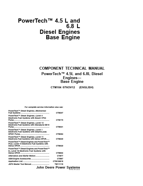
PowerTech™4.5L and6.8LDiesel Engines Base EngineFor complete service information also see:PowerTech™Diesel Engines—Mechanical Fuel Systems.......................................................CTM207PowerTech™Diesel Engines—Level 4Electronic Fuel Systems with Bosch VP44Pump.....................................................................CTM170PowerTech™Diesel Engines—Level 12Electronic Fuel Systems with Stanadyne DE10Pump.....................................................................CTM331PowerTech™Diesel Engines—Level 1Electronic Fuel Systems with Delphi/Lucas DP201Pump.........................................................CTM284PowerTech™Diesel Engines—Level 11Electronic Fuel Systems with Denso HPCR......CTM220PowerTech™Diesel Engines and PowerTech™Plus—Level 14Electronic Fuel Systems with Denso HPCR........................................................CTM320PowerTech™Diesel Engines and PowerTech™E—Level 16Electronic Fuel Systems with Denso HPCR........................................................CTM502Alternators and Starter Motors..........................CTM77OEM Engine Accessories...................................CTM67Application List....................................................CTM106819JDPS Master Tool Manual...................................TM111119COMPONENT TECHNICAL MANUAL PowerTech™4.5L and 6.8L DieselEngines—Base EngineCTM10407NOV12(ENGLISH)John Deere Power SystemsLITHO IN U.S.A.IntroductionDPSG,OUO1004,2767-19-29OCT10-1/1ForewordThis manual is written for an experienced technician.Essential tools required in performing certain service work are identified in this manual and are recommended for use.This manual (CTM104)covers only the engine base for all PowerTech™4.5L and 6.8L engines includingPowerTech™”Plus”engine model as well as PowerTech™”E”and PowerTech™”M”engine models.It is one of eight volumes on 4.5L and 6.8L engines.The following seven companion manuals cover fuel system and electronics repair,operation and diagnostics:•CTM207—Mechanical Fuel Systems•CTM170—Level 4Electronic Fuel Systems with Bosch VP44Pump•CTM331—Level 12Electronic Fuel Systems with Stanadyne DE10Pump•CTM284—Level 1Electronic Fuel Systems with Delphi/Lucas DP201Pump•CTM220—Level 11Electronic Fuel Systems with Denso High Pressure Common Rail•CTM320—Level 14Electronic Fuel Systems with Denso High Pressure Common Rail•CTM502—Level 16Electronic Fuel Systems with Denso High Pressure Common RailOther manuals will be added in the future to provide additional information on electronic fuel systems as needed.Live with safety:Read the safety messages in the introduction of this manual and the cautionspresented throughout the text of the manual.This is the safety-alert symbol.When you see this symbol on the machine or in this manual,be alert to the potential for personal injury.Use this component technical manual in conjunction with the machine technical manual.An applicationlisting in Section 01,Group 001identifiesproduct-model/component type-model relationship.See the machine technical manual for information on component removal and installation,and gaining access to the components.Information is organized in sections and groups for the various components requiring service instruction.Section 05summarizes all applicable essential tools,service equipment and tools,other materials needed to do the job,and service parts kits.Section 06summarizes all specifications,wear tolerances,and torque values.Before beginning repair on an engine,clean the engine and mount on a repair stand.(See Section 02,Group 010.)This manual contains SI Metric units of measure followed immediately by the U.S.customary units of measure.Most hardware on these engines is metric sized.Some components of this engine may be serviced without removing the engine from the machine.Refer to the specific machine technical manual for information on components that can be serviced without removing the engine from the machine and for engine removal and installation procedures.Read each block of material completely before performing service to check for differences in procedures orspecifications.Follow only the procedures that apply to the engine model number you are working on.If only one procedure is given,that procedure applies to all the engines in the manual.CALIFORNIA PROPOSITION 65WARNINGDiesel engine exhaust and some of its constituents are known to the State of California to cause cancer,birth defects and other reproductive harm.PowerTech is a trademark of Deere &CompanyRecord of ChangesPublication and Translation DateCTM104_17DEC09Section-Group Group Title Block Title Comment01-001Engine Identification andApplication Charts Engine Application Charts Moved to Application manual(CTM106819)02-050Camshaft,Balancer Shafts andTiming Gear Train Time Camshaft and Fuel InjectionPump(Non-HPCR Engines)Add procedure for injection pumpwith lock shaft timing.04-150Observable Diagnostics and Tests Test Engine Compression Pressure Added new compression adapterJDG10824,JDG11064,JDG1106506-210Diagnostic Specifications Intake Manifold Pressure(Turbocharger Boost)Specifications Update with new applications:•J06068HCQ07•PE6068HT082/083/085•J06068HCQ04•PE4045HLV56/58/60/62/64/66•PE6068AFM75•JO6068HBM04CD03523,00001D2-19-03SEP10-1/1DPSG,OUO1004,129-19-03DEC07-1/1RG7636—UN—23NOV973/4Right Rear ViewRG7638—UN—23NOV973/4Left Rear ViewRG7639—UN—23NOV973/4Right Front ViewRG7637—UN—23NOV973/4Left Front ViewPowerTech is a trademark of Deere&CompanyOUO1080,0000238-19-03DEC07-1/1R G 11932—U N —06N O V 013/4Right Front View—Two-Valve Head EngineR G 11931—U N —06N O V 013/4Left Rear View—Two-Valve Head EngineR G 13617A —U N —18M A Y 043/4Right Front View—Four-Valve Head EngineR G 13618A —U N —18M A Y 043/4Left Rear View—Four-Valve Head EnginePowerTech is a trademark of Deere &CompanyThanks very much for your reading, Want to get more information,Please click here, Then get the complete manualNOTE:If there is no response to click on the link above, please download the PDF document first, and then click on it.Have any questions please write to me: ******************************DPSG,OUO1004,130-19-29NOV07-1/1RG7641—UN—23NOV973/4Right Front ViewRG764—UN—23NOV973/4Left Front ViewRG7643—UN—23NOV973/4Right Rear ViewRG7642—UN—23NOV973/4Left Rear ViewPowerTech is a trademark of Deere&CompanyOUO1080,0000239-19-29OCT10-1/1OUO1083,00005FC -19-29OCT10-1/1R G 11934—U N —24O C T 013/4Right Front View—Two-Valve Head Engine R G 11933—U N —24O C T 013/4Left Rear View—Two-Valve Head EnginePowerTech™6.8L Engine With Electronic Fuel System—Tier 2/Stage IIR G 12199—U N —24M A Y 026068HF475Four-Valve Engine (Level 11Electronic Fuel Systemwith Denso High Pressure Common Rail)R G 12200—U N —24M A Y 026068HF475Four-Valve EngineOUO1083,00005FC -19-29NOV07-1/1PowerTech™Plus 6.8L Engine With Electronic Fuel System—Tier 3/Stage IIIAR G 13547—U N —11N O V 046068HF485Engine Shown (Electronic Fuel System WithDenso High Pressure Common Rail)R G 13546—U N —11N O V 046068HF485ShownPowerTech is a trademark of Deere &CompanyOURGP12,00001EA -19-29NOV07-1/1PowerTech™E 4.5L Engine With Electronic Fuel Systems (HPCR Fuel System)(Two-Valve Cylinder Head)R G 14632—U N —13A P R 064045HF285EngineR G 14633—U N —13A P R 064045HF285EnginePowerTech is a trademark of Deere &CompanyOURGP12,00001EB -19-29NOV07-1/1PowerTech™E 6.8L Engine With Electronic Fuel Systems (HPCR Fuel System)(Two-Valve Cylinder Head Model)R G 14634A —U N —29N O V 076068HF285Engine (3/4Right Front View)C D 31001—U N —29N O V 076068HF285Engine (3/4Left Front View)PowerTech is a trademark of Deere &CompanyCD03523,00001B4-19-03DEC07-1/1PowerTech™M 4.5L Engine withMechanical Fuel System and 17mm InjectorsC D 31002—U N —29N O V 074045HF280Engine (3/4Left Front View)PowerTech is a trademark of Deere &CompanyContentsSection01—General InformationGroup000—SafetyGroup001—Engine Identification and ApplicationChartsGroup002—Fuels,Lubricants and CoolantsSection02—Repair and AdjustmentsGroup010—Engine RebuildGroup020—Cylinder Head and Valves(Two-ValveHead Engines)Group021—Cylinder Head and Valves(Four-ValveHead Engines)Group030—Cylinder Block,Liners,Pistons and RodsGroup040—Crankshaft,Main Bearings and FlywheelGroup050—Camshaft,Balancer Shafts and TimingGear TrainGroup060—Lubrication SystemGroup070—Cooling SystemGroup080—Air Intake and Exhaust SystemGroup090—Fuel SystemGroup100—Starting and Charging SystemsSection03—Theory of OperationGroup120—Base Engine OperationSection04—DiagnosticsGroup150—Observable Diagnostics and TestsSection05—Tools and Other MaterialsGroup170—Repair Tools and Other MaterialsGroup180—Diagnostic Service ToolsGroup190—Dealer Fabricated Service ToolsSection06—SpecificationsGroup200—Repair and General OEM SpecificationsGroup210—Diagnostic SpecificationsOriginal Instructions.All information,illustrations and specifications in thismanual are based on the latest information available at the time of publication.The right is reserved to make changes at any time without notice.COPYRIGHT©2012DEERE&COMPANYMoline,IllinoisAll rights reserved.A John Deere ILLUSTRUCTION®ManualPrevious EditionsCopyright©1996,1998,2000,2002,2004,2005,2007,2008,2009,2010ContentsSection01General Information ContentsPage Group000—SafetyWork In Ventilated Area...............................01-000-1 Recognize Safety Information.....................01-000-1 Work in Clean Area.....................................01-000-1 Dispose of Waste Properly..........................01-000-2 Avoid Harmful Asbestos Dust......................01-000-2 Handle Fuel Safely—Avoid Fires.................01-000-2 Prepare for Emergencies.............................01-000-3 Handle Starting Fluid Safely........................01-000-3 Handle Fluids Safely—AvoidFires.........................................................01-000-3 Avoid High-Pressure Fluids.........................01-000-4 Use Proper Lifting Equipment......................01-000-4 Illuminate Work Area Safely........................01-000-4 Live With Safety...........................................01-000-5 Service Machines Safely.............................01-000-5 Handle Chemical Products Safely................01-000-5 Protect Against Noise..................................01-000-6 Remove Paint Before Welding orHeating....................................................01-000-6 Stay Clear of Rotating Drivelines.................01-000-7 Service Cooling System Safely...................01-000-7 Follow Safety Instructions............................01-000-8 Use Proper Tools.........................................01-000-8 Construct Dealer-Made ToolsSafely.......................................................01-000-8 Practice Safe Maintenance..........................01-000-9 Understand Signal Words............................01-000-9 Replace Safety Signs................................01-000-10 Prevent Battery Explosions.......................01-000-10 Protect Against High PressureSpray.....................................................01-000-10 Avoid Heating Near PressurizedFluid Lines.............................................01-000-11 Wear Protective Clothing...........................01-000-11 Wait Before OpeningHigh-Pressure Fuel System...................01-000-11 Handle Agricultural ChemicalsSafely.....................................................01-000-12 Handling Batteries Safely..........................01-000-13 Install All Guards.......................................01-000-13 Avoid Hot Exhaust.....................................01-000-14 Group001—Engine Identification andApplication ChartsEngine Serial Number PlateInformation...............................................01-001-1 OEM Engine Option Code Label.................01-001-3 Information Relative to EmissionsRegulations..............................................01-001-3 Group002—Fuels,Lubricants and Coolants Diesel Fuel...................................................01-002-1 Diesel Fuel Additive Products......................01-002-1Page Biodiesel Fuel..............................................01-002-2 Minimizing the Effect of ColdWeather on Diesel Engines.....................01-002-4 Handling and Storing Diesel Fuel................01-002-5 Lubricity of Diesel Fuel................................01-002-5 Testing Diesel Fuel......................................01-002-5 Oil Information for Uncertified orTier1Engines..........................................01-002-5 Diesel Engine Oil.........................................01-002-6 Oil Information for Tier2Engines................01-002-6 Diesel Engine Oil.........................................01-002-7 Oil Information for Tier3Engines................01-002-7 Diesel Engine Oil.........................................01-002-8 Diesel Engine Break-In Oil..........................01-002-9 Oil Filters.....................................................01-002-9 Grease.......................................................01-002-10 Alternative and SyntheticLubricants..............................................01-002-10 Lubricant Storage......................................01-002-10 Mixing of Lubricants...................................01-002-11 Heavy Duty Diesel EngineCoolant..................................................01-002-11 Supplemental Coolant Additives................01-002-12 Operating in Warm TemperatureClimates.................................................01-002-12 Additional Information AboutDiesel Engine Coolants andJohn Deere LIQUID COOLANTCONDITIONER.....................................01-002-13 Diesel Engine Coolant...............................01-002-14 Testing Diesel Engine Coolant...................01-002-14 Drain Intervals for Diesel EngineCoolant..................................................01-002-15ContentsGroup 000SafetyDX,AIR -19-17FEB99-1/1DX,ALERT -19-29SEP98-1/1DX,CLEAN -19-04JUN90-1/1Work In Ventilated AreaEngine exhaust fumes can cause sickness or death.If it is necessary to run an engine in an enclosed area,remove the exhaust fumes from the area with an exhaust pipe extension.If you do not have an exhaust pipe extension,open the doors andget outside air into the area.T S 220—U N —23A U G 88Recognize Safety InformationThis is a safety-alert symbol.When you see this symbol on your machine or in this manual,be alert to the potential for personal injury.Followrecommended precautions and safe operating practices.T 81389—U N —07D E C 88Work in Clean AreaBefore starting a job:•Clean work area and machine.•Make sure you have all necessary tools to do your job.•Have the right parts on hand.•Read allinstructions thoroughly;do not attemptshortcuts.T 6642E J —U N —18O C T 88DX,DRAIN -19-03MAR93-1/1DX,DUST -19-15MAR91-1/1DX,FIRE1-19-12OCT11-1/1Dispose of Waste ProperlyImproperly disposing of waste can threaten theenvironment and ecology.Potentially harmful waste used with John Deere equipment include such items as oil,fuel,coolant,brake fluid,filters,and batteries.Use leakproof containers when draining fluids.Do not use food or beverage containers that may mislead someone into drinking from them.Do not pour waste onto the ground,down a drain,or into any water source.Air conditioning refrigerants escaping into the air can damage the Earth’s ernment regulations may require a certified air conditioning service center torecover and recycle used air conditioning refrigerants.T S 1133—U N —26N O V 90Inquire on the proper way to recycle or dispose of waste from your local environmental or recycling center,or from your John Deere dealer.Avoid Harmful Asbestos DustAvoid breathing dust that may be generated whenhandling components containing asbestos fibers.Inhaled asbestos fibers may cause lung cancer.Components in products that may contain asbestosfibers are brake pads,brake band and lining assemblies,clutch plates,and some gaskets.The asbestos used in these components is usually found in a resin or sealed in some way.Normal handling is not hazardous as long as airborne dust containing asbestos is not generated.Avoid creating dust.Never use compressed air for cleaning.Avoid brushing or grinding material containing asbestos.When servicing,wear an approved respirator.A special vacuum cleaner is recommended to clean asbestos.If not available,apply a mist of oilor water on the material containing asbestos.T S 220—U N —23A U G 88Keep bystanders away from the area.Handle Fuel Safely—Avoid FiresHandle fuel with care:it is highly flammable.Do not refuel the machine while smoking or when near open flame or sparks.Always stop engine before refueling machine.Fill fuel tank outdoors.Prevent fires by keeping machine clean of accumulated trash,grease,and debris.Always clean up spilled e only an approved fuel container for transporting flammable liquids.Never fill fuel container in pickup truck with plastic bed liner.Always place fuel container on ground beforerefueling.Touch fuel container with fuel dispenser nozzle before removing can lid.Keep fuel dispenser nozzle in contactwith fuel container inlet when filling.T S 202—U N —23A U G 88Do not store fuel container where there is an open flame,spark,or pilot light such as within a water heater or other appliance.DX,FIRE2-19-03MAR93-1/1DX,FIRE3-19-16APR92-1/1DX,FLAME -19-29SEP98-1/1Prepare for EmergenciesBe prepared if a fire starts.Keep a first aid kit and fire extinguisher handy.Keep emergency numbers for doctors,ambulance service,hospital,and fire department near your telephone.T S 291—U N —23A U G 88Handle Starting Fluid SafelyStarting fluid is highly flammable.Keep all sparks and flame away when using it.Keep starting fluid away from batteries and cables.To prevent accidental discharge when storing thepressurized can,keep the cap on the container,and store in a cool,protected location.Do not incinerateor puncture a starting fluid container.T S 1356—U N —18M A R 92Handle Fluids Safely—Avoid FiresWhen you work around fuel,do not smoke or work near heaters or other fire hazards.Store flammable fluids away from fire hazards.Do not incinerate or puncture pressurized containers.Make sure machine is clean of trash,grease,and debris.Do not store oilyrags;they can ignite and burn spontaneously.T S 227—U N —23A U G 88DX,FLUID -19-12OCT11-1/1DX,LIFT -19-04JUN90-1/1DX,LIGHT -19-04JUN90-1/1Avoid High-Pressure FluidsInspect hydraulic hoses periodically –at least once per year –for leakage,kinking,cuts,cracks,abrasion,blisters,corrosion,exposed wire braid or any other signs of wear or damage.Replace worn or damaged hose assemblies immediately with John Deere approved replacement parts.Escaping fluid under pressure can penetrate the skin causing serious injury.Avoid the hazard by relieving pressure before disconnecting hydraulic or other lines.Tighten all connections before applying pressure.Search for leaks with a piece of cardboard.Protect hands and body from high-pressure fluids.If an accident occurs,see a doctor immediately.Any fluid injected into the skin must be surgically removed within a fewhours or gangrene may result.Doctors unfamiliarX 9811—U N —23A U G 88with this type of injury should reference a knowledgeable medical source.Such information is available inEnglish from Deere &Company Medical Department in Moline,Illinois,U.S.A.,by calling 1-800-822-8262or +1309-748-5636.Use Proper Lifting EquipmentLifting heavy components incorrectly can cause severe injury or machine damage.Follow recommended procedure for removaland installation of components in the manual.T S 226—U N —23A U G 88Illuminate Work Area SafelyIlluminate your work area adequately but e a portable safety light for working inside or under the machine.Make sure the bulb is enclosed by a wire cage.The hot filament of an accidentally broken bulbcan ignite spilled fuel or oil.T S 223—U N —23A U G 88DX,LIVE -19-25SEP92-1/1DX,LOOSE -19-04JUN90-1/1DX,MSDS,NA -19-03MAR93-1/1Live With SafetyBefore returning machine to customer,make sure machine is functioning properly,especially thesafety systems.Install all guards and shields.T S 231—19—07O C T 88Service Machines SafelyTie long hair behind your head.Do not wear a necktie,scarf,loose clothing,or necklace when you work near machine tools or moving parts.If these items were to get caught,severe injury could result.Remove rings and other jewelry to preventelectrical shorts and entanglement in moving parts.T S 228—U N —23A U G 88Handle Chemical Products SafelyDirect exposure to hazardous chemicals can causeserious injury.Potentially hazardous chemicals used with John Deere equipment include such items as lubricants,coolants,paints,and adhesives.A Material Safety Data Sheet (MSDS)provides specific details on chemical products:physical and health hazards,safety procedures,and emergency response techniques.Check the MSDS before you start any job using ahazardous chemical.That way you will know exactly what the risks are and how to do the job safely.Then follow procedures and recommended equipment.(See your John Deere dealer for MSDS’s onchemical products used with John Deere equipment.)T S 1132—U N —26N O V 90DX,NOISE -19-03MAR93-1/1DX,PAINT -19-24JUL02-1/1Protect Against NoiseProlonged exposure to loud noise can cause impairment or loss of hearing.Wear a suitable hearing protective device such asearmuffs or earplugs to protectagainst objectionable or uncomfortable loud noises.T S 207—U N —23A U G 88Remove Paint Before Welding or HeatingAvoid potentially toxic fumes and dust.Hazardous fumes can be generated when paint is heated by welding,soldering,or using a torch.Remove paint before heating:•Remove paint a minimum of 100mm (4in.)from area to be affected by heating.If paint cannot be removed,wear an approved respirator before heating or welding.•If you sand or grind paint,avoid breathing the dust.Wear an approved respirator.•If you use solvent or paint stripper,remove stripper with soap and water before welding.Remove solvent or paint stripper containers and other flammable material from area.Allow fumes to disperse at least 15minutes before welding or heating.Do not use a chlorinated solvent inareas where welding will take place.T S 220—U N —23A U G 88Do all work in an area that is well ventilated to carry toxic fumes and dust away.Dispose of paint and solvent properly.。
490QB柴油机设计(配气机构)

490QB柴油机设计(配气机构)摘要本设计的发动机机型为490QB柴油机,介绍了490QB柴油机的配气机构设计,配气机构各零件的详细设计。
依照本柴油发动机的设计技术要求,可以确定本柴油机的结构以及相关尺寸。
本机采用 形燃烧室,凸轮轴中置,龙门式机体方案。
为了使本次设计满足设计要求,所以根据燃机工程师手册,对本机进行工作过程热计算,结果表明此次设计满足其经济性和动力性要求。
发动机通过配气机构实现换气,即排出本循环已燃混合气和下一个循环吸入新鲜充量的进气排气过程,对于四冲程发动机来说,从排气门打开到进气门关闭的整个过程为换气过程。
而发动机动力性和经济性的好坏,在很大程度取决于换气过程的完善程度,因此配气机构的设计在本发动机设计中占有相当重的位置。
而配气机构设计的核心为提高充气效率,降低换气损失,进而改善了发动机的经济性和动力性。
设计气门采用双气门方案,即一进一出两气门,双气门方案结构简单,工作可靠,完全满足进排气要求,降低制造成本。
气门的驱动采用凸轮轴—挺住—推杆—摇臂—气门的驱动方案。
凸轮轴采用中置方案,形式为整体式凸轮轴,全支撑,满足强度要求,结构简单,加工精度高,具有很好的互换性。
本次设计主要包括气门弹簧,进排气门,进排气道和凸轮轴设计,而凸轮形状采用函数凸轮设计,由Mat lab程序计算得到挺柱的升程,速度,加速度,绘制曲线。
关键词:柴油机,凸轮,气门THE 490QB DIESEL ENGINE DESIGN(PISTON ANDCONNECTING ROD)ABSTRACTThe design of the diesel engine models for the 490QB introduced 490QB diesel engine valve train design, detailed design of each valve train parts. In accordance with the technical requirements for diesel engines, you can determine the structure and size of the diesel engine. The machine adopts the shape of the combustion chamber, the camshaft position, gantry body program. In order to meet the design requirements of this design, it is based on the internal combustion engine engineer manual process to work on the machine thermal calculations, the results show that the design meets its economy and power requirements.Engine for ventilation through valve body, the discharge of the circulating air and fuel mixture is next cycle inhale fresh charge intake and exhaust, for four-stroke engines, the exhaust valve to open the intake valve closing the whole process of the ventilation process. The engine power and economy is good or bad, to a large extent depend on the degree of perfection of ventilation process, so Valve design occupies very heavy position in this engine design. The core Valve designed to improve volumetric efficiency, reduce ventilation losses, thereby improving the economy of the engine and power. Valve double valve design scheme, namely one into a two-valve, dual valve scheme is simple, reliable, fully meet the requirements of the intake and exhaust, reduce manufacturing costs .Valves driven by the camshaft - tappet - putt - rocker - valve drive solutions. Camshaft scheme used in the home, in the form of the monolithic camshafts, fully supported to meet the strength requirements, simple structure, high precision, with good interchangeability.The design includes valve springs, intake and exhaust valves, and intake and exhaust camshafts road design, and the use of a cam-shaped cam design function, calculated by the Mat lab program tappet lift, velocity, acceleration, plotted.Key words: diesel engine, cam, valve目录前言 (1)第一章整体设计 (2)§1.1 490QB柴油机 (2)§1.2 柴油机的设计 (2)§1.3 设计容和方法 (3)第二章燃机工作过程的热计算 (4)§2.1 一般参数计算 (4)§2.2 进排气过程计算 (4)§2.3 压缩终点参数计算 (5)§2.4 燃烧过程的计算 (6)§2.5 膨胀终点参数的计算 (6)§2.6 指示参数的计算 (7)§2.7 有效参数的计算 (7)第三章配气机构的总体布置 (9)§3.1 气门数目、驱动方式,布置 (9)§3.2 凸轮轴布置和传动方案确定 (9)第四章气门组的设计 (10)§4.1 气门的设计 (10)§4.2 气门导管的设计 (15)§4.3 气门通路面积的校核 (15)第五章气门弹簧的设计 (20)§5.1 气门弹簧的概述 (20)§5.2 气门弹簧的尺寸确定 (20)第六章凸轮轴和气门附件的设计 (26)§6.1 凸轮轴的设计 (26)§6.2 挺柱的设计 (31)§6.3 推杆和摇臂的设计 (32)结论 (33)参考文献 (34)致 (35)附录 (36)前言距第一台燃机诞生,经过100多年的发展,在工程师们孜孜不倦的努力下,发动机不断的得到改进和进步,性能不断得到改进与创新,到今天能为人类社会活动不可或缺的一员,支持着社会的发展与进步,给人们带来了非常大的便捷,近些年,随着柴油机高压共轨、缸直喷、净化等技术的发展,以较低的排放输出强大的动力,有着无可比拟的优势。
d495q3a柴油机凸轮轴毛坯的设计大学论文
学院毕业论文(设计)D495Q3A柴油机凸轮轴毛坯的设计学生姓名学号指导教师学院机电工程学院专业机械设计制造及其自动化年级2016论文答辩日期 2016 年 6 月 1 日学院D495Q3A柴油机凸轮轴毛坯的设计完成日期:指导教师签字:答辩小组成员签字:摘要凸轮轴是活塞发动机里的一个部件。
它的作用是控制气门的开启和闭合动作。
虽然在四冲程发动机里凸轮轴的转速是曲轴的一半(在二冲程发动机中凸轮轴的转速与曲轴相同),不过通常它的转速依然很高,而且需要承受很大的扭矩,因此设计中对凸轮轴在强度和支撑方面的要求很高,其材质一般是特种铸铁,偶尔也有采用锻件的。
毛坯的形状和尺寸的确定,除了将毛坯余量附在零件相应的加工表面上之外,有时还要考虑到毛坯的制造、机械加工及热处理等工艺因素的影响。
在这种情况下,毛坯的形状可能与工件的形状有所不同。
关键词:凸轮轴;毛坯;加工余量;材料;Thesis TitleThe camshaft is a component in the piston engine. Its role is to control the valve opening and closing actions. Although in four stroke engine camshaft crankshaft speed is half ( in two stroke engine camshaft and crankshaft speed of same ), but usually it's speed is still high, but to bear great torque, therefore the design of cam shaft on the strength and support requirements are very high, generally the material special cast iron, occasionally using forgings.Blank shape and size determination, in addition to the blank margin is attached to the parts corresponding to the machined surface, sometines even taking into account the blank of manufacturing, machining and heat treatment process factors. In this case, the blank shape may vary with the shape of the workpiece.Key word: camshaft; rough machining allowance; material;目录前言 (1)1凸轮轴毛坯 (1)1.1常见种类的毛坯 (1)1.2凸轮轴毛坯加工的选择 (2)1.3毛坯形状及尺寸的确定 (2)2凸轮轴 (2)2.1凸轮轴的构造 (2)2.2凸轮轴的位置 (3)2.3凸轮轴的传动 (4)2.4凸轮轴的失效形式 (4)2.5凸轮轴的生产技术 (4)2.6凸轮轴的选材 (4)3凸轮轴毛坯的设计 (6)3.1凸轮轴毛坯的设计要求 (6)3.2凸轮轴毛坯的经济适用性 (6)4实例 (7)5总结 (10)参考文献 (11)致谢 (12)前言现代生产生活中柴油发动机具有不可忽视的作用。
山西宏伟NXZ-4B5四驱四缸发兰使用说明书(1)
N X Z-45B中心传动高效浓缩机使用说明书淮北矿山机器制造有限公司目录一、机器的用途及使用范围二、型式、规格、基本参数三、机构说明、工作原理及特点四、机器的安装五、机器的试车六、机器的操作七、机器的维护及保养八、液压站使用说明九、液压原理图十、电器原理图一、机器的用途及使用说明中心传动式浓缩机主要用于选矿过程中湿选精矿的脱水处理,系作脱水第一阶段------浓缩之用。
一般设置于精选与过滤设备之间,有时也作精选之前脱水。
同时在化学工业、造纸和选煤厂用来进行脱水作业。
二、型式、规格、基本参数型式中心传动式规格ф45m基本参数见下表三、机构说明、工作原理与特点1.(1)机器的组成:吊挂装置、传动装置、桥架、水泥池、转笼、耙架、布料井、平台栏杆、液压站、电控箱等部件组成。
(2)池体:NXZ型的池体分水泥池体及钢构池体两种。
水泥池体由用户自备。
用户订购钢板池须特别注明,否则制造厂不供。
排矿用泵制造厂不供。
(3)入料管:内部耐磨衬由用户自备。
(4).结构关系:传动装置的底座与中心水泥柱连接,立柱与底座连接,传动装置的传动部分坐落在立柱上,马达减速机的小齿轮驱动回转支撑外圈,外圈与回转支架相连,油缸与座圈把合,带动传动装置升降,桥架一端安装在支柱上、一端与池体固定。
转笼与传动装置的回转部分相连,入料与布料装置相连,布料装置与桥架相连。
耙子、副耙与转笼相连。
池体底部有排矿口,用管子与泵连接。
2 机器的结构特点、传动和工作过程NXZ型浓缩机是我厂研制开发的一种新型、高效浓缩机。
该机采用絮凝技术,将沉降与深层过滤相结合,矿浆直接给入浓缩机的压缩区,在池内形成滤床层,后续给入的矿浆中未絮凝的细小颗粒,随水流上升,途经滤床层,与其中的颗粒碰撞,上升动能损耗,与其它颗粒结合在一起下沉。
从而增加了底流浓度,减少了溢流水浊度。
由于采用了絮凝剂,颗粒形成絮凝团,沉降速度加快,处理能力提高.桥架固定在浓缩池及支柱上,它是维护人员进入浓度机中心部位的通道。
495G汽油机活塞的设计与开发
495G汽油机活塞的设计与开发太原理工大学机械学院 张翠平摘 要简要介绍活塞的工作条件和设计要求,着重介绍495G汽油机活塞的结构特点。
试验结果表明:该活塞满足495G汽油机的性能要求。
关键词:汽油机 活塞 设计495G汽油机是太原理工大学和榆次内燃机厂共同研制开发的新产品,它在492汽油机的基础上进行了扩缸处理。
为此必须重新设计活塞。
新设计的活塞经过反复试制、改进、试验论证和实践考核,证明满足使用性能要求,现已投入生产。
1 活塞的工作条件及设计要求活塞是内燃机中工作条件最恶劣的零件,它受到气体压力,往复惯性力及侧压力的周期性冲击力的作用,它的工作温度高且不均匀,同时活塞的平均速度高又润滑不良。
根据活塞的工作条件,对其设计主要的要求是强度高,质量轻,导热性、抗磨性和缸内导向性好,同时还要保证机器运转时噪声小,易于制造,成本低。
2 活塞材料的选择及热处理由于活塞的工作条件恶劣,对于活塞材料,要求其具有高的机械性能,尤其是较高的高温强度,小的线膨胀系数,较高的导热系数,较小的密度以及良好的减摩性能与耐磨、耐蚀性能等。
495G汽油机活塞材料采用共晶硅铝合金,硅含量11%~13%,并夹有少量的Mg、Mn、Cu等元素,是汽油机活塞的常用材料,合金中硅元素能使线膨胀系数和密度下降,耐磨性、耐蚀性、硬度、刚度和疲劳强度提高,铸造流动性改善。
活塞毛坯用金属模铸造,以保证毛坯具有良好的铸造质量。
活塞毛坯需要进行热处理,以消除活塞铸件的内应力,增加热稳定性,增加强度和刚度,热处理后硬度HB=95~140,热稳定性可达0.025/100mm,抗拉强度要求大于200MPa。
3 活塞的结构特点495G汽油机活塞顶是平的,头部呈圆柱形,上面有两道气环槽和一道油环槽,裙部为椭圆形,并且上下呈正锥形。
活塞销孔的中心线偏向发动机的右侧,减少了活塞通过上止点换向时的敲击声,活塞销座与活塞头部采用了能增强活塞强度的连接结构。
活塞外表面镀锡,以改善活塞与缸壁的磨合性能。
柴油发电机组技术参数说明
柴油机***********************************************************************************************************※功率说明额定功率它适用于替代市电在变化的负载下无时间限制地供电。
对于变化的负载而言.平均每12工作小时有一个小时可以有10%的超载能力.但每年超载运行累计不超过25小时。
每250工作小时变化的负载不可超过额定功率的70%.每年在100%额定功率下运行累计不可超过500小时。
备用功率相当于在正常电源中断时运行连续发电的功率。
它适用于在建立良好电网的地区.市电断电的情况下.在变化的负载下提供备用功率。
此功率没有超载能力。
每年在100%额定功率下运行累计不可超过25小时。
每年累计运行时间不可超过200小时.发动机最多使用80%的负载因素。
※功率修正发动机功率依据ISO3046标准大气条件.100kpa大气压.25℃进气温度及30%相对温度来设定。
如果现场条件与标准条件不同.则必须按照相应的发动机功率修正程序修正发动机的输出功率。
修正程序考虑到海拔高度、相对温度和环境温度等负面影响.来降低相对于标准大气状态下的发动机最大输出功率。
若不修正.可能导致排气温度升高、排烟量增加及涡轮增压器转速升高。
※负载承受特性机组在突然加载时.发动机必须有足够的频率恢复能力。
频率下降反应主要取决于涡轮增压器的惯性.其次是燃油系统。
※冷却系统大皇冠柴油发电机组标准配置采用自带风扇闭式循环液体冷却方式。
其冷却系统循环回路包括水泵、发动机缸体与盖内的水管、节温器、节温器体与水泵间的旁通管、散热水箱、管路和软管扩机油冷却器。
对于非标准机组.如分体散热水箱型机组.水箱散热器由热交换器代替.同时还有补充水箱和远程冷却风扇等.如远程冷却风扇安装位置相对较高.还应增加过渡水箱.以防止热交换器因内压大而损坏。
※冷却液机组冷却液有以下三种功能:1、提供足够的热传递能力2、防止冷却系统内金属材料锈蚀3、提供足够的防冻保护冷却液可以由水和防冻液或水和防锈液混合组成.其中.水的PH值应在7—7.5之间.通常建议选用纯净水。
- 1、下载文档前请自行甄别文档内容的完整性,平台不提供额外的编辑、内容补充、找答案等附加服务。
- 2、"仅部分预览"的文档,不可在线预览部分如存在完整性等问题,可反馈申请退款(可完整预览的文档不适用该条件!)。
- 3、如文档侵犯您的权益,请联系客服反馈,我们会尽快为您处理(人工客服工作时间:9:00-18:30)。
课程设计说明书
设计题目:柴油机的曲柄连杆机构设计班级:J动力(机械)1201
学号:**********
姓名:***
指导老师:***
日期:2015年1月12日
目录
1 任务要求 (1)
2 柴油机曲柄连杆机构动力计算 (2)
2.1 原始参数 (2)
2.2 动力计算 (3)
结论 (12)
致谢 (12)
参考文献 (13)
1任务要求
(1).柴油机的曲柄连杆机构设计
(2).计算活塞运动规律及曲柄连杆机构受力分析
(位移,速度,加速度,气体力,往复惯性力,连杆力,切向力,径向力,侧压力,单缸输出转矩,总转矩)
(3).编写课程设计说明书
内容包括:封面,目录,原始资料及数据,设计计算及说明。
参考资料及文献等,计算机打印,装订成册。
2 柴油机曲柄连杆机构的动力学计算
2.1 原始参数
原始参数及已知条件 1) 柴油机型号:495 2) 燃烧室形式:涡流室 3) 气缸直径D :95mm 4) 活塞行程S :115mm 5) 活塞平均速度(m/s):7.67 6) 总排量:0.817L 7) 标定转速(r/min):2000 8) 压缩比ε:18~20 9)
连杆长:210mm
10) 质量:活塞810g
连杆大头1382g ,小头505g 11) 曲柄半径R :57.5mm ;
12) 连杆比
2738.0==
l R
λ;
13) 活塞面积
2
2
65.784
cm D F p ==
π;
14) 标定功率e N :8.8kw (12PS ); 15) 曲轴旋转角速度s rad n
/21030
==
πω 222/44100s rad =ω;
16) 曲轴销中心的切向速度s m R /075.12=ω; 17) 曲柄销中心的切向加速度22/75.2535s m R =ω;
2.2 动力计算
1)运动分析及动力计算 (1)运动参数的计算 活塞运动规律计算公式: 活塞位移:
)]sin 11(1
cos 1[22ϕλλ
ϕ--+
-=r x
活塞速度:)2sin 2
(sin ϕλ
ϕω+==r x
v
活塞加速度:2)2cos (cos ωϕλϕr x a +==
连杆摆角:)sin arcsin(αλβ=
以上个参数具体位置见 图2-1 曲柄连杆机构简图所示。
计算活塞在一个循环内各位置的运动规律,结果如表2-1所示。
画出活塞运动规律曲线图,如图2-2所示。
表2-1 495柴油机活塞运动规律计算表
曲轴转角)(
ϕ
连杆摆角)(
β
)(mm x
)/(s m v
)/(2s m a
0 0.00 0.00 0.00 3230.04 10 2.73 1.11 2.66 3149.64 20 5.37 4.39 5.19 2914.68 30 7.87 9.68 7.47 2543.17 40 10.14 16.73 9.39 2063.06 50 12.11 25.21 10.88 1509.39 60 13.72 34.74 11.89 920.73 70 14.91 44.90 12.41 335.42 80 15.64 55.29 12.46 -212.09 90 15.89 65.53 12.08 -694.29 100 15.64 75.26 11.33 -1092.75 110 14.91 84.24 10.28 -1399.13 120 13.72 92.24 9.03 -1615.02 130
12.11
99.13
7.62
-1750.51
140 10.14 104.83 6.13 -1821.94 150 7.87 109.27 4.61 -1848.88 160 5.37 112.46 3.07 -1850.97 170 2.73 114.36 1.53 -1844.81 180 0.00 115.00 0.00 -1841.46 190 -2.73 114.36 -1.53 -1844.81 200 -5.37 112.46 -3.07 -1850.97 210 -7.87 109.27 -4.61 -1848.88 220 -10.14 104.83 -6.13 -1821.94 230 -12.11 99.13 -7.62 -1750.51 240 -13.72 92.24 -9.03 -1615.02 250 -14.91 84.24 -10.28 -1399.13 260 -15.64 75.26 -11.33 -1092.75 270 -15.89 65.53 -12.08 -694.29 280 -15.64 55.29 -12.46 -212.09 290 -14.91 44.90 -12.41 335.42 300 -13.72 34.74 -11.89 920.73 310 -12.11 25.21 -10.88 1509.39 320 -10.14 16.73 -9.39 2063.06 330 -7.87 9.68 -7.47 2543.17 340 -5.37 4.39 -5.19 2914.68 350 -2.73 1.11 -2.66 3149.64 360 0.00 0.00 0.00 3230.04
图2-2 495柴油机活塞运动规律曲线
(2)动力参数的计算
i.计算在一个循环中活塞连杆曲轴所受的运动分力。
结果如表3-2所示。
绘制)(x f N p =的变化曲线,如图3-4所示; 绘制
)
(),(),(ϕϕϕf p f p f p j g ===的变化曲线,如图3-5所示;
绘制)(),(1ϕϕf ra p f p ==的变化曲线,如图3-6所示。
绘制曲轴输出扭矩曲线,如图3-7所示。
可见,单缸柴油机曲轴的输出扭矩曲线与其曲柄切向力曲线形状完全一样,只是纵坐标值相差p RF 倍。
图3-4
)(x f p N 的变化曲线
图3-5
)
(
),
(
),
(ϕ
ϕ
ϕf
p
f
p
f
p
j
g
=
=
=
的变化曲线
图3-6
)
(
),
(ϕ
ϕ
τ
f
p
f
p
ra
=
=
的变化曲线
图3-7 曲轴输出扭矩曲线
结论
495型柴油机是我国应用较广的柴油机机型,根据初始条件进行了曲柄连杆机构的运动学、动力学计算。
从计算校核的结果看,其动力性基本达到了同类产品中较好的水平。
总体来说,495柴油机的设计基本满足了设计的要求,具有结构轻巧、移动方便、安装简单等特点。
致谢
在经历了两个多星期的辛苦工作后,我的495柴油机设计终于按期完成,在此期间,从CAD工程图的绘制等一系列的工作,让我获益匪浅,其不仅是一次本科期间专业技能上的终极锻炼,更培养了我持之以恒的做事品质和发现问题解决问题的能力,为我大学四年中的所学知识做了梳理和巩固。
此次课程设计的让我对柴油机的结构有了较为彻底的了解,并学到了很多先前上课时学不到的知识。
我相信这些收获必将为即将参加工作的我提供不少可借鉴之处。
最后,我要感谢所有帮助我的老师,在此期间,他们对我的课程设计提出了很多宝贵的意见,为我课程设计的顺利完成提供了莫大帮助,在此,深表感谢。
参考文献
[1] 周龙保.内燃机学.北京:机械工业出版社,2005.1
[2] 袁兆成. 内燃机设计. 北京. 机械工业出版社.2008
[3] 王德海.内燃机动力学.江苏理工大学内燃机教研室,1998.8
[4] 杜家益.热动专业课程设计.汽车学院动力机械工程系,2015.12。