3par文档
3par存储配置文档
3par存储配置文档
HP 3PAR 管理地址:192.168.100.2
用户名:3paradm
密码:3pardata
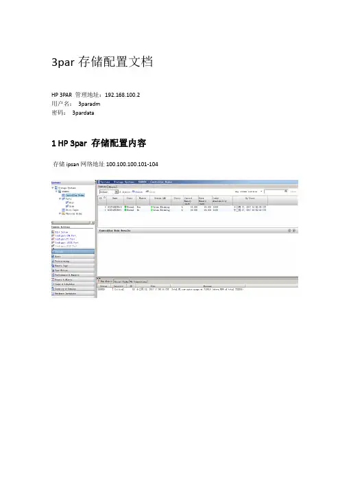
1 HP 3par 存储配置内容
存储ipsan网络地址100.100.100.101-104
2 多路径软件配置内容
3 HP 3par 存储配置流程
笔记本端安装3par管理软件HP 3PAR Management Console,
IP:使用OOTB中设置的IP.
用户名和密码:3paradm/3pardata.
进入Management Console有以下几个步骤:
共五个步骤:
1:配置FC端口
2:创建CPG
3:创建HOST
4:创建VV
5:把VV指定给HOST
1:配置FC端口,选择PORT端口,设置Connection Node为Host设置Type为Point(现在系统默认已配置好,此步骤可以省略,检查一下即可)
2:进入IMC在3PAR中创建CPG:(如果使用系统自带的CPG,可省略此步骤)
3:创建VV: (一个VV最大不能超过16T)
想建几个磁盘就重复几次上面的操作,注意磁盘空间即可。
4:创建HOST主机:
5:把磁盘指定给HOST主机:。
3PAR主打胶片V2.1-2017-5

外部全闪存阵列性价比第1名 $0.23/IOPS
第 1名
第1个进入性价比前10的全闪存阵列
领先
545,164 IOPS
中端存储的最高性能
Confidential 保密
>62GB/s
18
最完整的闪存阵列产品线
3M
最具扩展性的全闪存阵列
3PAR 20850 3PAR 20840
3PAR在线换代
10
3PAR存储联邦技术
增强数据的流动性
应用加速 性能型 SLA
高达 60PB 10M IOPS 一键平衡阵列间的负载
生产阵列 经济型 SLA 生产阵列 性能型 SLA
开发和测试
Confidential 保密
11
满足闪存优化数据中心的需求
存储联邦: 数据可以在线的在存储之间自由流动
可以在存储联邦中的不同类型3PAR(全闪存、高端和中端)间在线迁移容量和平衡IO负载
为关键业务设计,为闪存优化,企业级的功能和性能
Confidential 保密
5
3PAR存储不断创新的历程
2013
6月 3PAR进入全闪存市场 12月 SSD的容量超过20%
自动、智能地提供服务
应用加速 便捷运维 降低风险 投资回报
简便的提供数据中心存储能力
统一的用户使用体验和可编程的REST APIs接口
+
HPE OneView HPE 3PAR SSMC
+
HPE RMC
+
HPE StoreFront Remote
3PAR自动化管理
自动优化的架构
Confidential 保密
HP-3PAR存储日常管理手册

HP-3PAR存储日常管理手册————————————————————————————————作者:————————————————————————————————日期:2a d m i n技术支持服务热线800-810-3860/400-810-3860V e r s i o n1.0目录一,3PAR存储介绍 (3)1.3PAR InSpire架构 (3)2.3PAR InForm软件 (4)3.3PAR主要构件 (7)4.3PAR组件编号系统 (9)5.3PAR LED状态指示灯 (10)二,日常配置 (11)1.添加主机Host (11)2.创建CPG (12)3.创建VV虚拟磁盘 (13)4.分配VV虚拟磁盘 (15)三,日常维护 (17)1.存储开机步骤 (17)2.存储关机步骤 (17)3.存储日志Insplore收集 (17)4.管理机SP日志SPLOR收集 (19)5.特定信息CLI命令行收集 (21)四,HP支持服务模式 (22)1.主动式响应--SP Call-Home (22)2.被动式响应—HP服务热线 (22)3.被动式响应—邮寄存储日志 (23)May.2012Version 1.0admin一,3PAR存储介绍3PAR 系列存储平台具有超高的灵活性和高效性,突破了公共基础设施中传统存储阵列的局限性。
作为精简配置、绿色存储以及存储虚拟化技术的先行者,3PAR能帮助用户降低能耗、实履行环保义务,还可削减最高达50%的存储总拥有成本1.3PAR InSpire架构紧密集群化、多客户端的3PAR InSpire 构架设计,消除了传统整体式和模块化阵列价格高昂和扩展十分复杂的弊端。
用户可以一开始只购买较小的系统,之后,随着业务量的增加再进行扩展,即经济且连续地添加新的应用和工作负载,所有这些都将在一个单一、自动化的分层阵列中进行。
内置Thin Built In™的 Gen3 /Gen4 ASIC内置Thin Built In™的3PAR Gen3 ASIC 提供一种高效、基于硬件的零检测机制。
HP 3PAR存储解决方案模板v2

贵单位HP- 3PAR存储解决方案目录贵单位 (1)第1章. ......................................................................... 前言5第2章. ......................................................................... 简介52.1用户现状 (5)2.2用户需求 (6)第3章. ................................................................... 需求分析73.1容量分析 (7)3.2性能分析 (7)3.3维护分析 (10)3.3.1存储部署 (10)3.3.2存储配置调整 (11)3.3.3存储扩容 (12)3.3.4性能优化 (14)3.4高可用性需求 (15)3.5容灾需求 (16)第4章. ................................................................... 解决方案164.1方案概述 (16)4.2方案配置 (18)4.3方案基本优势 (19)4.3.1全网状控制器集群架构 (19)4.3.2独特的双分类处理单元 (19)4.3.3全新的磁盘划分方式 (20)4.3.4高性能存储系统 (22)4.3.4存储的高可用性 (23)4.3.5业务连续性 (24)4.3.6存储数据精简 (25)4.3.7动态的存储优化 (27)4.3.8数据分层以与热点数据迁移 (28)4.3.9虚拟资源调配 (29)4.3.10智能的管理界面 (31)4.4VM WARE环境解决方案 (31)4.4.1提高VMware vSphere投资回报 (32)4.4.2提高虚拟化环境的整合力度 (33)4.4.3简化虚拟化环境的管理 (37)4.5O RACLE环境解决方案 (40)4.5.1 Oracle环境面临的挑战 (40)4.5.2 HP-3PAR Thin与Oracle ASM环境的完美结合.. 414.5.3 Oracle环境的更高磁盘利用率 (45)4.5.3 智能和主动的分层存储技术 (46)4.5.5 总结 (48)第1章.前言承蒙贵单位对HP-3PAR的信任和厚爱,提供我们参与其系统建设的机会,我们不胜感激与深表荣幸。
3PAR 基础功能-尚道计划实验手册v1
Rev. 15.33
i
HP Storage TME, Houston
ii
Rev. 15.33
HP 3PAR Basic Provisioning
实验 1 HP 3PAR 基础供应实验 Lab 1 实验 1
Objectives 目标
After completing this lab, you should be able to: 完成这个实验,您将可以:
Contents 目录
Lab 1—HP 3PAR Basic Provisioning 实验 1—HP 3PAR 基础供应实验
Objectives 目 标..................................................................................................... 1 Requirements 需 求 ............................................................................................... 2 Exercise 1—Installing the SSMC ........................................................................... 4 练习 1—安装 SSMC .............................................................................................. 4 Exercise 2—Configuring the SSMC ..................................................................... 10 练习 2—配置 SSMC ............................................................................................ 10 Exercise 3—Creating a CPG ............................................................................... 19 练习 3—创建一个 CPG ........................................................................................ 19 Exercise 4—Creating a VV .................................................................................. 24 练习 4—创建一个 VV ........................................................................................... 24 Exercise 5—Installing Host Explorer .................................................................... 27 练习 5—安装 Host Explorer ................................................................................. 27 Exercise 6—Exporting a VV to a host .................................................................. 32 练习 6—挂载一个 VV 到一台主机 ........................................................................ 32 Exercise 7—Installing and configuring MPIO ....................................................... 39 练习 7—安装并配置 MPIO ................................................................................... 39 Exercise 8—Making a volume available to Windows ........................................... 46 练习 8—让卷可用于 Windows .............................................................................. 46
3PAR_Power OFF ON Procedures
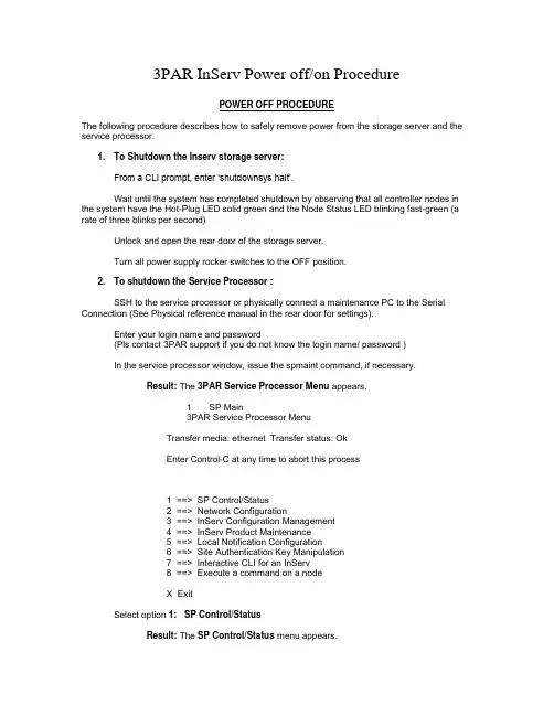
3PAR InServ Power off/on ProcedurePOWER OFF PROCEDUREThe following procedure describes how to safely remove power from the storage server and the service processor.1. To Shutdown the Inserv storage server:From a CLI prompt, enter ‘shutdownsys halt’.Wait until the system has completed shutdown by observing that all controller nodes in the system have the Hot-Plug LED solid green and the Node Status LED blinking fast-green (a rate of three blinks per second)Unlock and open the rear door of the storage server.Turn all power supply rocker switches to the OFF position.2. To shutdown the Service Processor :SSH to the service processor or physically connect a maintenance PC to the Serial Connection (See Physical reference manual in the rear door for settings).Enter your login name and password(Pls contact 3PAR support if you do not know the login name/ password )In the service processor window, issue the spmaint command, if necessary.Result: The 3PAR Service Processor Menu appears.1 SP Main3PAR Service Processor MenuTransfer media: ethernet Transfer status: OkEnter Control-C at any time to abort this process1 ==> SP Control/Status2 ==> Network Configuration3 ==> InServ Configuration Management4 ==> InServ Product Maintenance5 ==> Local Notification Configuration6 ==> Site Authentication Key Manipulation7 ==> Interactive CLI for an InServ8 ==> Execute a command on a nodeX ExitSelect option 1: SP Control/StatusResult: The SP Control/Status menu appears.1 SP CONTROL3PAR Service Processor MenuTransfer media: ethernet Transfer status: OkSP Control FunctionsEnter Control-C at any time to abort this process1 ==> Display SP Version2 ==> Reboot SP3 ==> Halt SP4 ==> Stop InServ related Processes5 ==> Start InServ related Processes6 ==> File Transfer Monitor7 ==> SP File Transfer Trigger8 ==> Reset Quiesce state in Transfer process9 ==> Mount a CDROM10 ==> Unmount a CDROM11 ==> SP Date/Time maintenance12 ==> Manage NTP configuration13 ==> Display SP status14 ==> SP User Access Control15 ==> SP Process Control Parameters16 ==> Maintain SP Software17 ==> SP File maintenance18 ==> De-install SP ( Back-in-the-box )X Return to previous menuSelect option 3, Halt SP.Result: The SP SHUTDOWN window appears.1.3.1 SP SHUTDOWN3PAR Service Processor MenuConfirmationEnter Control-C at any time to abort this processHalt will power off the SP! Are you certainyou want to halt the SP now?(y or n)Type y and press Enter.Result: The following output is displayed:.Broadcast message from root (ttyS0) Fri Oct 7 12:51:33 2006...The system is going down for system halt NOW !!Verify that the blue LED on the front of the service processor is no longer illuminated.3 Remove AC to the storage server by turning off the PDU circuit breakers of ALL fourPDUs in the cabinetPOWER ON PROCEDURETurn on AC power to the cabinet(s) by turning on all the PDU circuit breakers of ALL four PDUs. Then turn on all the power switches of all the disk enclosures, controller nodes, batteries and the service processor.To verify that the system is operational, observe that all drive chassis LEDs that are illuminated SHOULD be solid green and all controller node status LEDs are blinking green once per second. (It may help best to remove all bezels to assist in visual inspections) Verify that the blue LED on the front of the service processor is illuminated.NOTESThe system takes approximately five minutes to become fully operational, providing it was gracefully shut down. If the system was powered off abruptly, powering on could take considerably longer.Gracefully means you issued shutdownsys halt and then switched the PDUs off when the nodes were halted.Abruptly means that power was simply turned off to the system, causing battery backup of the cache data to the IDE disks.Extremely abruptly means an uncontrolled shutdown, or powering off a drive chassis cabinet (causing logical disks to become degraded/failed), and then powering off the node cabinet.Considerably longer means the time varies depending on how many logical disks exist and must go through ldchk.。
3PAR Remote Connectivity
3PAR InServ ConnectivityThe intent of this document is to present an overview of the remote connectivity options offeredon the InServ product line. Additionally it will outline the benefits our customers receive when they choose remote connectivity, along with the limitations if remote connectivity is not available. Enabling remote connectivity allows HP-3PAR support to deliver rapid, proactive response with complete 24x7 remote monitoring and analysis to identify issues and proactively communicate them to customers. Allowing remote connectivity with remote operations enables “lights out” online remote software updates and service actions that eliminate scheduling and onsite visit delays.If customers do not allow any form of remote connectivity, HP-3PAR’s ability to quickly identifythe root cause of an issue can be severely impacted. InServ issues may take longer to determine root cause, which would result in extending the time required to resolve the reported issue. Depending on the type of issue encountered, the delay in problem resolution can be significantly longer than if remote connectivity was available.All of the connectivity options described in this document are enabled via the Service Processor. The Service Processor (SP) is a HP-3PAR provided server that is housed within the basecabinet of each InServ Storage Server. The SP serves as the communication interface withinthe customer’s IP network for all service-related communication to and from the InServ Storage Server. It gathers diagnostic information from the InServ and periodically transmits it over a secure network to HP-3PAR Central, if allowed. All customer-authorized remote service connections to a given InServ leverage the Service Processor as the conduit for executingservice actions on the InServ.The connectivity options available to our customers are listed below, each one will be explained and where appropriate the customer requirements will be documented.∙Secure Network Mode∙SP mode∙Local notification and RAP Forwarding∙Weekly File TransferIn all cases the customer can control how and when communications takes place and if Remote Operations is allowed. This concept will be explored in the following detailed explanation ofeach transfer mode.Secure Network ModeThis is the preferred method of transfer as it is secure, easy for customers to implement in their firewall, and offers customers the most access control options.Secure Network Mode utilizes the HP-3PAR Secure Service Architecture. The HP-3PAR Secure Service architecture provides secure service communication between the HP-3PAR InServ Storage Servers at a customer’s site and HP-3PAR Central, enabling secure diagnostic data transmission and remote service connections. Diagnostic data can be transferred frequently and maintained centrally on a historical basis. As a result, manual intervention in the support process is minimized and pro-active fault detection and analysis is enhanced. Further, with remote operations connectivity for troubleshooting, HP-3PAR Customer Service and Engineering can deliver the fastest, most reliable response and quickest resolution time.The Secure Service Architecture leverages the industry-standard HTTP over Secure Socket Layer (HTTPS) protocol for all external communication, ensuring that the communication is secure and any data transmission is encrypted. The Secure Service Architecture is also firewall-friendly. HP-3PAR only requires that HTTPS Port 443 be enabled on the customer’s external firewall, and all communication with HP-3PAR Support is initiated in an outbound manner.Secure Network Mode is enabled as part of the Service Processor “Moment of Birth” which occurs at installation time. All of the information required to set up Secure Network Mode is captured in the SA Document.The customer requirements for Secure Network Mode are as follows:Port 443 open (industry standard HTTPS port) for file transfer and Remote OperationsThis can also be enabled anytime after the install by scheduling the change with the HP-3PAR Service Planning Specialist (SPS) team. The HP-3PAR SPS team will engage the HP-3PAR National Technical Support Specialist (NTSS) or 3PAR Deployment Center (3DC) team to plan and support the activity. The SPS team will also schedule the activity with the customer.Please note that the inbound connection is only needed for remote operations and it does not need to remain on constantly. Both the inbound and outbound access is controlled by the customer via Customer Controlled Access (CCA) setting on the Service Processor. This setting can be modified by the customer at any time.SP ModeSP mode is the HP-3PAR legacy method of file transfer and also provides secure file transfer between the InServ on the Customer site and HP-3PAR Central in Fremont, CA. This optionwill be retired in the near future.The protocol for the connection between the Service Processor and HP-3PAR Central is SSH. The following firewall ports at the customer site must be opened to allow the file transfer to take place.For outbound connectivity (file transfer to HP-3PAR Central)Outbound access from the Service Processor to (66.126.187.144) ORIGINATES from ports 1024 – 65535 TO port 22 on andrequires all related session traffic to be allowed.For inbound connectivity (remote operations to the InServ)Inbound (remote operations) access from to the ServiceProcessor ORIGINATES from ports 1024-65535 TO port 22 on the Service Processorand requires all related session traffic be allowed.Please note that the inbound connection is only needed for remote operations and it does not need to remain on constantly. Both the inbound and outbound access is controlled by the customer via Customer Controlled Access (CCA) setting on the Service Processor. This setting can be modified by the customer at any time.Local Notification and Rap ForwardingFor customers that will not allow remote connectivity, while they will not receive the full benefitof the proactive support that HP-3PAR offers, there are options which will provide limited notification of alerts.Local Notification utilizes customer email to send events to customer defined individuals and/or group-ids. The Service Processor is configured during the “Moment of Birth” with information supplied by the SA Doc to send events to the defined email addresses. The limitation of only using Local Notification is that it places ALL responsibility for problem reporting on the customer. HP-3PAR are not made aware of any problems with the InServ unless the customer reports them first.Additionally RAP (Real-time Alert Processing) forwarding can be enabled, if no outbound connection is possible, to email these events to HP-3PAR Central in a format that is acceptedby the Service Tools Platform. These events will be catalogued and appropriate notifications to HP-3PAR support will be generated. While this does not provide detailed information it doesprovide notifications of problems and system warnings, and it does allow HP-3PAR to be proactively notified of system alerts.The following customer specific information is required to set up Local Notification at the Service Processor:Mail Host IP AddressMail Host Domain NameCompany or Site NameSite NumberTime ZoneMail to NamesMail AddressesWeekly File TransferThis option is also for customers that will not allow remote connectivity, while they will not receive the full benefit of the proactive support that HP-3PAR offers, there are options which will provide limited notification of alerts.The Service Processor gathers logs and automatically creates a zipped file called“3PAR_WEEKLY...” every Sunday (~ 4 AM, PT). This file contains much of the pertinent system information that would have been transferred during the week if transfers were allowed, such as alerts, failure information, information regarding temperature, voltage and battery conditions, and various hardware and software states.The customer can download this file from the Service Processor on Monday morning and send it to HP-3PAR for analysis via email or ftp. This provides a delayed view of the events that have occurred during the previous week, but does allow the HP-3PAR Support Team to identify problems or potential issues.Policy Manager (optional software)Policy Manager is an optional feature, purchased separately, and designed to work in tandem with Secure Network Mode. Policy Manager is software that is loaded onto a customer server and is completely customer controlled. Policy Manager allows the customer to set policies around Remote Operations as well as capturing an audit log of all activity. The Policy Manager is defined in a separate document but is mentioned here to make the reader aware of it.Policy Manager allows customers to define and implement the following key policies for remote operations:File Upload – Defines whether file uploads of diagnostic data to HP-3PAR Central are allowed or disallowed.File Download – Defines whether file downloads from HP-3PAR Central are allowed or disallowed.Remote Session – Defines whether or not remote sessions for remote serviceability can be established with HP-3PAR Central. These sessions are only available to customers where HP- 3PAR is the primary support provider.Each of the above policies can be configured with one of the following values:Always Allow – All remote connection requests are allowedAlways Deny – All remote connection requests are denied.Ask – The Service Processor seeks approval via email within a configured timeout window from the configured customer administrator for any remote connection requests. If approved, the remote connection request is allowed. If denied or the configured timeout window elapses, the remote connection is denied.。
3par配置说明书
3PAR创建主机、划盘划盘的具体步骤:
1. 登陆3par管理界面HP 3PAR Management Console 4.3
IP:
User Name: 3paradm
Password:3pardata
2. 新建和查看HOST信息
➢登陆界面→HOST→Common Actions→create host
➢进入创建界面→不用勾选→next
➢填写主机名称、选择操作系统类型→next
➢从左选框选择该主机HBA卡WWN点至右选框;若该主机HBA卡WWN在左选框未列出来,则手动下下方输出框输入WWN添加至右选框→next
➢完成创建,点击左菜单栏host即可查看已建主机列表。
3. 创建CPG
➢点击左下菜单Provisioning→create CPG
➢进入创建界面→不用勾选→next
➢填写CPG名称、选择CPG raid级别和类型→next
➢创建成功→左上菜单点击CPGs可查看已建CPG信息
4. 创建VV
➢选择左下菜单Provisioning→create virtual volume
➢进入创建界面:填写VV name、VV size;选择VV类型、选择所在CPG名称→finish
➢完成创建,点击左菜单栏Virtual Volumes即可查看已建VV列表。
5. 分配VV到主机
➢点击左下菜单Export Volumes
➢进入分配VV界面不用勾选→next
➢在左选框选择需要分配的VV,右选框选择VV需要分配至的主机,LUN勾选Auto (可选择多个VV至一台主机或者选择一个VV至多台主机)→next
➢完成分配VV,点击左上菜单Virtual Volume即可查看VV与HOST对应关系。
3PAR产品介绍
500 400
Chunklets
300
200 100
0 1 20 39 58 77 96 Physical Disks
After Dynamic Optimization
600
Free Used
500 400
Chunklets
300
200 100
0 1 20 39 58 Physical Disks 77 96
传统阵列
InServ
15
©2010 3PAR Inc. All rights reserved. | 3PAR Confidential
虚拟资源调配 Thin-Provisioning
传统阵列
- 按照预留的空间进行分配 Exported Volumes Exported Volumes Exported Volumes Exported Volumes
Autonomic Tiering and Data Movement
Save ~30% on $/IOPS and $/GB vs. Fibre Channel
3PAR Company Confidential
©2010 3PAR Inc. All rights reserved. | 3PAR Confidential
Month/Day/Year, Presentation Title
存储体系架构的发展
多控制器 冗余架构 双控制器架构 投入 单控制器
服务级别/性能
4
©2010 3PAR Inc. All rights reserved. | 3PAR Confidential
磁盘阵列的架构演变
传统阵列
3par 存储架构
- 1、下载文档前请自行甄别文档内容的完整性,平台不提供额外的编辑、内容补充、找答案等附加服务。
- 2、"仅部分预览"的文档,不可在线预览部分如存在完整性等问题,可反馈申请退款(可完整预览的文档不适用该条件!)。
- 3、如文档侵犯您的权益,请联系客服反馈,我们会尽快为您处理(人工客服工作时间:9:00-18:30)。
3par存储操作手册
1 、 VSP-3par存储报警和日志收集平台,安装在虚拟机上。
该虚拟机IP 192.200.45203~204
访问方式:
Https:
用户名 3parcust
口令:3parInServ
Action 下面的InSplore 在有问题的情况下,并且VSP断开外网连接,手动收集日志作分析。
如果想检查系统健康状态,点击Health Check 进行检查,如下图:
2、3par管理软件安装在B7-5上的管理客户端
HP 3PAR Management Console 用来对3par存储进行管理
(1)IP address 选择 3par控制器心跳地址 192.200.45.200~201 Username :3paradm
Password :3pardata
进入看到如下界面
(2)新建HOST主机:
点击后,点击“create host”新建主机,点击“Export volume”将划出的虚拟盘挂到主机上。
新建主机:只需填写name和选择host os
接下去选择对应主机的wwn号
注:一般服务器的wwn号能在HBA卡边上的标签上查到。
HP刀片服务器的WWN号需要登录刀箱管理地址进行查看:老10.17.200.233,新10.17.200.224
https://10.17.200.233/ admin、admin
点击,→→(WWN号) 选择完WWN号之后直接点击finish
(2)点击provisioning,
Create Virtual Volume,新建虚拟盘,
主需要填写:name,选择fully provisioned,在size中填写大小,选择的单位大小,选择raid级别,一般选择raid5,之后点击 finish
(3)挂盘:将虚拟盘挂接到新建的主机上。
,点击“export volume”,
然后分别:选中“左边的虚拟盘”和“右边的主机”,(可多选),之后点击finish,这样就将虚拟盘挂到了需要的主机上了。
(4)更改新建出来的虚拟盘的空间大小,注:只能增加,不能减少。
双击ss7400,下拉菜单中点击“virtual volume”在右边TAB中选择“virtual volume”,能看到新建的虚拟盘的列表。
选中要增加空间的虚拟盘,邮件单击,选择
可以增加大小,单位,更改虚拟盘的名称:
(5)查看存储使用情况:
点击system。