基于PROE的四缸内燃机凸轮配气机构的结构设计及运动仿真分析
基于的ProE直摆凸轮机构运动仿真(DOC)
摘要本课题所研究的直、摆组合凸轮机构是一种新型的机构类型,该机构通过直动从动件凸轮机构与摆动从动件凸轮机构组成联动凸轮机构,能够将主动件的转动转化为从动件上某点沿预期的曲线轨迹并以预期的运动规律运动。
在对直、摆组合凸轮机构理论分析的基础上,我们对直、摆组合凸轮机构进行了Pro/e 运动仿真,精确求解出了各凸轮的理论廓线、实际廓线及各构件结构尺寸等。
丰富了机械原理学科的设计理论及内容,适应了在机构设计方面许多学者致力于寻求凸轮机构的精确解和使凸轮曲线多样化及从动件轨迹多样化的要求。
最后,选择预期圆线轨迹为例,利用计算机辅助设计(Pro/ENGINEER)对该机构进行零、部件及总体造型分析设计,并利用Pro/ENGINEER对该直、摆组合凸轮机构进行了运动仿真,以验证理论的正确性和可行性。
因此,对直、摆组合凸轮机构进行深入地研究有着较大的理论和现实意义,有广阔的应用前景。
关键词:Pro/e应用组合机构凸轮设计运动仿真AbstractThe Z.B Combinatory Cam Mechanism is a kind of new-type mechanism, it can come into a kind of combinatory-movement mechanism which joints translation driven member cam and swing follower cam .It can translate the revolution of the driving body into a point of the driven body which has the ability to move around the anticipation curvilinear path and move based on the anticipation movement rule.Based on the theory in analyzing Z.B Combinatory Cam Mechanism,we simulate the mechanism in applying VB,solving the profile of theory,reality,cutter of cams,and the subject and dimension of all components exactly.Enriching the design-theory and content of the subject about mechanical principal .Adapting the request of many scholars in component design for searching the exact solution about cam-entity and making the cam-curve various and follower-profile various.Lastly, taking the four-leaf rose curve for example, applying the Pro/ENGINEER to design the curve, entity and motive emulate for verifying the truth and feasibility of the theory.Nowadays, researching the Z.B Combinatory Cam Mechanism, having the significance in theory and reality .The prospect is extensive.Key words:Pro/ENGINEER Application Combination Mechanism Cam Design Motive Emulate目录第一章前言---------------------------------------------------------------------------------------------------11.1 直、摆组合凸轮机构的研究意义---------------------------------------------1 1.2 凸轮机构以及组合机构的研究和发展状况------------------------------------4 1.3 Pro/ENGINEER WildFire软件的简介------------------------------------------5 1.4 本课题的主要研究内容----------------------------------------------------6 第二章直、摆组合凸轮机构基本设计及计算机辅助设计---------------------------72.1 直、摆组合凸轮机构基本设计----------------------------------------------7 2.2 直、摆组合凸轮机构凸轮各种廓线设计--------------------------------------142.2.1直动凸轮廓线求解--------------------------------------------------152.2.1.1 直动凸轮理论廓线-------------------------------------------152.2.1.2 直动凸轮实际廓线-------------------------------------------152.2.2 摆动凸轮廓线求解-------------------------------------------------162.2.2.1 摆动凸轮理论廓线-------------------------------------------162.2.2.2 摆动凸轮实际廓线-------------------------------------------16 2.3 计算机辅助设计---------------------------------------------------------16 2.4 设计举例---------------------------------------------------------------17 2.5 本章小结---------------------------------------------------------------20 第三章直、摆组合凸轮机构Pro/ENGINEER的设计-------------------------------213.1 创建凸轮模型-----------------------------------------------------------21 3.2 运动仿真的设计---------------------------------------------------------23 3.3 Pro/ENGINEER实体运动仿真-----------------------------------------------253.4 机械仿真结果分析及保存-------------------------------------------------29第四章小结----------------------------------------------------------------32 参考文献-------------------------------------------------------------------33第一章前言1.1直、摆组合凸轮机构的研究意义本课题研究的是直、摆组合凸轮机构如图1-1所示。
基于proe的机构运动仿真ppt课件

编辑版pppt
22
四、运动环境
4. 阻尼
与弹簧不同,阻尼为耗散力,它可以作用于连接轴、两主体 之间、槽运动副。 直接点击按钮 ,其中C为阻尼系数。
编辑版pppt
23
四、运动环境
5. 力/扭矩
可以通过力/扭矩来模拟机构运动的外部环境。 直接点击按钮 其类型分为“点力”与“主体扭矩”,即力与扭矩。和其他 矢量相同,定义需要指出“模”和“方向”。
编辑版pppt
17
2. 齿轮(续)
三、运动副
齿轮类型分为一般、正、锥、涡轮、 齿条与小齿轮。
对于所有类型,需对每一个齿轮选 取连接轴,传动比一般都采用齿数比的 方式予以确定。
对于齿条类,齿条的定义通常需要 指出“滑动杆”连接轴,传动比定义一 般使用 mm/rev,即齿轮旋转一周,齿条 前进的距离。
30
1. 回放
六、获取结果
使用回放功能主要可以实现运动干涉检测、创建运动包络和动 态影像捕捉。指令为点击按钮
创建运动包络
保存为*.fra文件
播 放 动 画
逆向播放 重新开始
上一帧 循环播放
停止
编辑版pppt
捕捉为图片 或动态影像
正向播放 快进至结尾 下一帧 结尾处反转
31
➢回放:轨迹曲线
轨迹曲线用来表示机构中某一元素相对于另一零件的运动。分为“轨迹曲线”与 “凸轮合成曲线”两种: “轨迹曲线”表示机构中某一点或顶点相对于另一零件的运动。 “凸轮合成曲线”表示机构中某曲线或边相对于另一零件的运动。
编辑版pppt
18
2. 齿轮(续)
实例演练
三、运动副
编辑版pppt
19
四、运动环境
1. 重力
基于PRO_E的凸轮机构结构设计及其运动仿真分析_毕业设计正文
湖北文理学院毕业设计(论文)正文题目基于PRO/E的凸轮机构结构设计及其运动仿真分析专业机械设计制造及其自动化班级姓名学号指导教师职称┊┊┊┊┊┊┊┊┊┊┊┊┊装┊┊┊┊┊订┊┊┊┊┊线┊┊┊┊┊┊┊基于Pro/E的凸轮机构的结构设计及其运动仿真分析摘要:凸轮机构是机械中一种常用的机构,它结构简单,紧凑,工作可靠,设计方便,利用不同的凸轮轮廓线可以使从动件实现任意给定的复杂运动规律。
同时它兼有传动,导向和控制机构的各种功能和优点。
因此在包装机,纺织机,印刷机,内燃机以及农业机具等具有广泛的运用。
传统的凸轮设计有图解法和解析法,图解法形象直观,结构简单,但是手工作图选取的等分数有限,误差较大,较繁琐。
解析法设计虽然解决了凸轮设计的精度问题,但是要得到完整的凸轮轮廓线需要建立复杂的数学公式,编制复杂的程序,编程和计算工作量大。
总之,传统的运动分析法是一种间断的,静态的分析方法。
本文利用Pro/E强大的三维实体建模功能,建立凸轮机构的装配模型,然后进行运动学分析,仿真凸轮机构的运动情况,最后将所设置的构件的位移,速度,加速度变化情况以表格形式输出,通过修改仿真模型的参数,快速的修改和优化设计方案。
关键词:凸轮机构;Pro/E;三维建模;运动仿真。
┊┊┊┊┊┊┊┊┊┊┊┊┊装┊┊┊┊┊订┊┊┊┊┊线┊┊┊┊┊┊┊The cam mechanism based on Pro/E structure design andkinematics simulation analysisAbstract:the cam mechanism is a kind of commonly used mechanical mechanism, it has the advantages of simple structure, compact structure, reliable work, convenient design, using different cam contour line allows the follower to realize any given motion law of complex. At the same time it has the drive, guide and control mechanism of the various features and advantages. So in the packaging machine, textile machine, printing machine, internal combustion engines and agricultural machinery is widely used. The traditional cam design graphic method and analytic method, graphical method is visual, simple structure, but the chart manually selected score is limited, the error is large, complex. Analytic design method solves the problem of precision cam design, but to get the full cam contour line need to build a complex mathematical formula, the preparation of complex procedures, programming and calculation. In short, the traditional motion analysis is a kind of discontinuous, static analysis method. In this paper, using Pro/E powerful3D entity modeling function, establish the cam assembly model, then analyses the kinematics simulation of cam mechanism, motion, the setting member of displacement, velocity, acceleration in form of output, by modifying the parameters of the simulation model, rapid modification and optimization design.Key words: cam mechanism; Pro/E;3D modeling; motion simulation.┊┊┊┊┊┊┊┊┊┊┊┊┊装┊┊┊┊┊订┊┊┊┊┊线┊┊┊┊┊┊┊目录1前言 (1)1.1本课题研究的目的和意义 (1)1.2国内外的研究现状及发展趋势 (2)1.3研究的主要内容、途径和技术线路 (3)2凸轮轮廓线的设计 (4)2.1凸轮机构的分类 (4)2.2从动件的运动规律及选取原则 (4)2.3凸轮轮廓线的设计 (5)2.3.1凸轮轮廓线设计方法的基本原理 (5)2.3.2凸轮轮廓曲线的计算 (5)2.4凸轮机构基本尺寸的确定 (7)2.5滚子半径的选择 (8)3凸轮机构的实体建模与装配 (10)3.1Pro/E软件简介.............................. 错误!未定义书签。
基于pro-e的凸轮设计与仿真
凸轮组件的装配
组件装配
伺服电机的创建
机构的运动( 动画)
谢谢各位老师参与我的答辩
通过样条曲线构建的轮廓
第二章 凸轮的实体建模
第三章 凸轮加工仿真
1.建立凸轮的毛坯,基 于本设计中凸轮形状, 设计用长方体的毛坯。 2.先精加工出凸轮的中 轴,然后基于轴孔装卡。 3.采用指状铣刀进行加 工,刀具半径 24 。
加工仿真界面
仿真过程视频
第四章 机构运动仿真
1.进入装配模型 2.安装支座、凸轮轴、凸轮、连杆等组件 3.进入机构分析界面建立驱动 4.建立凸轮与从动件连接 5.结果分析
第一章 凸轮的设计
1.结构的总体设计 2.从动件运动规律的计算 3.凸轮机构基本尺寸设计 4.凸轮轮廓设计 5.凸照设计要求,将凸 轮极坐标半径(E列 )、凸轮对应转角值 代入电子表格,通过 公式运算计算出在笛 卡尔坐标的凸轮轮廓 点坐标。(F列为横 坐标,G列为纵坐标 )
Pro-e5.0功能介绍
• • • • • • • 1、界面 2、草绘功能 3、建模功能 4、意外退出自动保存。 5、打印可以预览 6、可以计算曲面的质量 7、数控加工与先前版本有所区别
草绘功能
本设计中创建的凸轮立体模型
数控仿真
设计规划
一、凸轮的参数设计 二、凸轮零件的实体建模 三、凸轮加工仿真 四、凸轮装配 五、凸轮的运动仿真 五、零件的数控加工及 NC代码的自动生成
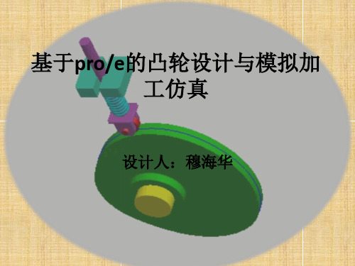
基于pro/e的凸轮设计与模拟加 工仿真
设计人:穆海华
PRO/E简介
Pro/ENGINEER是美国PTC公司所开发的3D实 体模型设计系统,是现代CAD技术发展中的 里程碑。它属于高端的CAD软件,支持复杂 产品开发的多方面需求。与其他同类的设 计软件相比,Pro/ENGINEER不仅功能强大,而 且易学易用,尤其是Pro/ENGINEER的Wildfire 更适合初学者使用。在Pre/ENGINEER提供 的各种功能中,建模(即构建空间实体)是最基 本的应用。
毕业设计(论文)基于proe的四缸内燃机凸轮配气机构的结构设计及运动仿真分析

湖北文理学院毕业设计(论文)正文题目基于PRO/E的四缸内燃机凸轮配气机构的结构设计及运动仿真分析专业机械设计制造及其自动化班级机制0812班姓名学号指导教师职称2012年5 月23日基于PRO/E的四缸内燃机凸轮配气机构的结构设计及运动仿真分析摘要:配气机构作为内燃机的重要组成部分,其设计合理与否直接关系到内燃机的动力性能、经济性能、排放性能及工作的可靠性、耐久性。
随着内燃机高功率、高速化,人们对其性能指标的要求越来越高,要求其在高速运行的条件下仍然能够平稳、可靠地工作,因而对其配气机构提出了更高的要求。
配气凸轮型线是配气机构的核心部分,配气凸轮型线设计是配气机构优化设计的重要途径之一。
模拟计算和实验研究是内燃机配气机构研究两种重要手段。
运用多体力学的方法对配气机构进行了动态仿真分析,采用数字多体程序的方法,建立了配气系统的理论模型,进行配气机构的运动学、动力学分析,除了得到气门的升程、速度、加速度外,还考虑了摇臂与气门之间的碰撞,以及摇臂支座的柔性。
因此得到气门与摇臂之间的碰撞力,摇臂支座的柔性衬套的受力,气门弹簧力,凸轮轴支座反力,气门座反力及凸轮与摇臂之间的压力角等。
为凸轮型线、摇臂形状和整个配气机构的设计改进提供了重要依据。
利用pro/e强大的分析仿真功能, 对凸轮式配气机构的运动特性以及弹簧刚度对系统运动的影响进行了仿真分析, 得出弹簧刚度与气门振动的关系图, 为改善系统动力学性能和关键零部件设计提供了依据。
利用计算机软件仿真, 有利于降低研发成本并缩短产品的开发周期。
关键词:内燃机;配气机构;凸轮型线;优化设计;汽车;发动机;配气系统;顶置凸轮;动态仿真Based on the PRO / E four cylinder internal combustionengine cam mechanism design and motion simulationanalysisAbstract:The valve train is one of the most important mechanisms in a internal combustion engine, whether the performances are good or bad, that affecting the power performance, economic performance, emissions performance of the engine, as well as affecting the reliability and wear performances of the whole engine. Along with the requests of the engine’s high power, super-speed, people demand a higher index. That is, when the engine runs under a high speed, it can still work steadily and dependably, which demand that the valve train system should have a high performance. Cam profile is the hard core of the valve train, which design is one of the important ways to carry out valve train optimal design. Simulation calculation and experimentation research are two important ways to carry out research and development on valve train of internal-combustion engine.Valve-train has been dynamically simulated by the multi-body method.A theory model has been built for the valve train by using the digital multi-body program.Not only the lift height,speed and acceleration of valve but also the collision between valve and rocker and the flexibility of rocker support are taken into account.Therefore, the collision force between valve and rocker ,loading on the flexible bearing of rocker support, valve spring force, can support counter - force, valve ring counter - force and direction angle of acting force between cam and rocker have been carried out. The important basis on design improvement for cam profile, rocker form and valve form and valve train have been provided.This paper analyzed the dynamic characteristics of a cam-type valve t rain and the influence o f the spring stiffness on the systematic mot ion by using Pr o / E .The relationship between stiffness of spring and vibration of valve was got ten. The work ha s provided a basis for improving the system's dynamic char act eristics and designing the key components. T hereby , computer simulation can cut down the pro duct cost and shorten the development cycle.Key words:Internal combustion engine; Valve train; Cam profile; Optimal design;Automobile Engine Valve -train system Overhead camshaft Dynamic simulation目录1绪论 (5)1.1本课题研究的目的和意义 (5)1.2配气机构优化设计的目的及意义 (6)2基于PRO/E的配气机构的结构设计 (7)2.1配气机构总体骨架设计 (7)2.2凸轮轴设计 (9)2.3凸轮的设计 (9)2.4挺杆的设计 (9)2.5推杆的设计 (9)2.6气门杆的设计 (10)2.7弹簧的设计 (10)2.8使用PRO/E创建配气机构的相关元件 (11)3配气机构的装配 (15)3.1首先装配凸轮轴并准确定位 (15)3.2装配平底从动件 (16)3.3装配弹簧 (17)3.4装配汽门挺杆 (18)4四缸内燃机凸轮配汽机构动态仿真分析 (20)4.1内燃机凸轮配汽机构运动仿真准备工作 (20)4.2内燃机凸轮配汽机构运动仿真分析 (21)5本文总结 (27)参考文献 (29)致谢 (30)1绪论1.1 本课题研究的目的和意义现代内燃机不断向高速高强度方向发展. 作为内燃机三大机构之一的配气机构, 如果设计不当, 势必产生很大的冲击、振动、噪音, 严重时, 气门会产生反跳与飞脱, 这将严重影响到内燃机的动力性与经济性. 同时, 由于速度的提高, 凸轮机构的润滑与磨损也成为一个不可忽视的问题. 现代大功率柴油机普遍采用下置凸轮轴式配气机构,配气机构的好坏又对柴油机的性能指标、可靠性及寿命有着很大的影响,其设计是否优良直接影响柴油机的性能指标。
基于Pro/E的配气机构三维运动仿真设计

计的方法。
关 键词 : 气机 构 ; 配 凸轮 型 线 ; 配气 相 位 角 ; 真 仿 中 图分 类 号 : P l T 3 文 献 标 识码 : B
利用 Po E软件 进行 零件 的三维 设计 已经被 越来 越广 泛地 应 用 , 而 , r/ 然 要利 用它 进 行 机 构 的 运 动 仿 真 设 计 还 比较 复 杂 。 此 次 配 气 机 构 设 计 以 R 2 2 0 J 柴油 机为原 型 , 于 Po E野 火 3 0版 , 用 了 T p—d w 1V 8 Z 型 基 r/ . 采 o o n协 同设计 模 式 , 骨架 模 型定位 , D U F精确 凸轮 轮 廓建 模 和 三 维 机构 连 接 方 法 , 实现 了全 三维 配气机 构 的运动 仿 真 。
成 两个 部分 , 以上级 骨架 的安 装定 位信 息为 设计 基准 进行 建模 , 这样 做 的好
处 是两个 总 成部 分可 同步 进 行 , 不 干 涉 。其 中 , 缸 盖 总 成 组 件 由气 缸 互 气
盖 、 臂组 件 、 摇 横臂 组 件 、 门组件 等 组 成 ; 气 凸轮 轴 总成 组 件 由凸 轮轴 、 杆 推 组件、 挺杆 组件 组成 , 用整 体式 结构 , 采 分左 、 2根 , 右 两缸 1节 , 为 3个 单 分
分 , 个部 分 分别 以一个 骨 架模 型 零 件 进行 三 维 建 模 , 个 零 件 结 构 简单 , 每 每
睇
鬟 鬟鬟l黪 _
容 易建模 。然后 将所 有 完 成 的零件 进 行相 应 的合 并及 剪 切就 可 以完 成气 缸 盖 的建模 了 , 个零 件 的特征 过 程非 常 干净 , 续 如有 设 计改 动 只需 在相 应 整 后 的骨 架模 型 中进 行 即可 , 改 容 易 , 修 出错 率 低 。 图 1 图 2 图 3分 别 显 示 了 、 、
基于proe的凸轮机构设计和仿真

目录中文摘要 (I)英文摘要 (II)第1章任务与课题条件 (1)1.1任务 (1)1.2课题条件 (1)第2章凸轮机构及PRO/E简介 (2)2.1凸轮机构简介 (2)2.2 PRO/E简介 (7)第3章盘形凸轮创建过程 (10)3.1新建零件 (10)3.2创建拉伸特征 (10)3.3创建方程曲线 (10)3.4创建图形特征 (11)3.5创建可变剖面扫描特征 (12)3.6创建孔特征 (12)第4章其余零件设计 (14)4.1从动杆设计 (14)4.2连杆设计 (14)4.3滑块设计 (15)第5章装配 (16)第6章机构仿真 (17)6.1定义凸轮从动连接机构. (17)6.2添加驱动器 (17)第7章运动分析及结果分析 (20)7.1运行分析 (20)7.2结果回放 (21)7.3结果分析 (22)结论 (25)参考文献 (26)致谢 (27)摘要机械产品的运动分析和仿真在机械产品的设计中是不可缺少的重要环节。
在各类机械的传动结构中,凸轮结构有着广泛的应用,根据凸轮机构的设计原理,提出了在pro/e 中实现凸轮设计及实体造型的方法,并主要利用Pro/e Wildfire的运动学分析模块Mechanism对凸轮机构进行了运动学分析和仿真,这对凸轮机构的优化设计将提供较大的帮助。
本文通过对对心直动尖顶盘型凸轮机构进行运动仿真分析,更加明确了该机构的优缺点,对于该机构的优化设计以及该机构以后的用途将提供指导作用。
关键词:凸轮机构 Pro/E 运动仿真运动分析AbstractSimulation technology in the mechanical products design plays an important role. In some mechanical transmission structures,the cam mechanism is used widely, Introducs the method of cam design and modeling in Pro/E,and mainly expiains the kinematics analysis and the simulasion by using Pro/E Wildfire Mechanism ,it will provide useful help to the optimized design of cam mechanism. This article through to the heart of translational knife-edge plate cam mechanism motion simulation analysis, more clearly the advantages and disadvantages, for the optimal design of the mechanism as well as the agency later use will provide guidance.Key Words:cam mechanism ;Pro/E;motion simulation;motion analysis第1章任务与课题条件1.1 任务为了对凸轮机构进行更好的优化设计以及对凸轮机构以后的应用起指导作用,因此基于pro/e对盘型凸轮机构进行设计与运动仿真,并对速度和加速度进行分析,研究该盘型凸轮机构的运动情况,并对该凸轮机构以后的应用作出预测。
基于ProE的凸轮机构运动仿真

本文将以凸轮机构为例介绍其运动仿真的过程, 该凸 轮机构由凸轮、连杆、摆杆 1、摆杆 2、机架五个零件构成。
2 0 1 2. 0191 ( 中下 旬 刊 )
观理察工
基于 Pro/E 的凸轮机构运动仿真分析
中 图 分 类 号 :G712
郭丽
(南京信息职业技术学院 江苏·南京 210046)
文 献 标 识 码 :A
文章编号:1672-7894( 2012) 33-0091-02
摘 要 凸轮机构是各类机器中广泛使用的传动机构,本 文 通 过 Pro/E 软 件 对 凸 轮 机 构 的 实 体 建 模 和 运 动 仿 真 分 析,得到了摆杆的位移、速度、加速度的运动曲线,简化了设 计过程,提高了设计效率。 关键词 凸轮机构 Pro/E 运动仿真 运动分析 Motion Simulation Analysis of the Cam Mechanism with Pro/Engineer // Guo Li Abstract The cam mechanism is a kind of drive mecha- nisms, is widely used in various types of machines. The ar- ticle introduces the model and motion simulation analysis of the cam mechanism with the Pro/E software, gains the dis- placement, speed and acceleration curves of rocker, simpli- fies the design process, improves the design efficiency. Key words the cam mechanism;Pro/E;motion simulation;mo- tion analysis Author's address Nanjing College of Information Technolo- gy,210046,Nanjing,Jiangsu,China
- 1、下载文档前请自行甄别文档内容的完整性,平台不提供额外的编辑、内容补充、找答案等附加服务。
- 2、"仅部分预览"的文档,不可在线预览部分如存在完整性等问题,可反馈申请退款(可完整预览的文档不适用该条件!)。
- 3、如文档侵犯您的权益,请联系客服反馈,我们会尽快为您处理(人工客服工作时间:9:00-18:30)。
┊┊┊┊┊┊┊┊┊┊┊┊┊装┊┊┊┊┊订┊┊┊┊┊线┊┊┊┊┊┊┊┊┊┊┊┊┊湖北文理学院毕业设计(论文)正文题目基于PRO/E的四缸内燃机凸轮配气机构的结构设计及运动仿真分析专业机械设计制造及其自动化班级机制0812班姓名李旭东学号08116249指导教师职称李梅副教授2012年5 月23日┊┊┊┊┊┊┊┊┊┊┊┊┊装┊┊┊┊┊订┊┊┊┊┊线┊┊┊┊┊┊┊┊┊┊┊┊┊基于PRO/E的四缸内燃机凸轮配气机构的结构设计及运动仿真分析摘要:配气机构作为内燃机的重要组成部分,其设计合理与否直接关系到内燃机的动力性能、经济性能、排放性能及工作的可靠性、耐久性。
随着内燃机高功率、高速化,人们对其性能指标的要求越来越高,要求其在高速运行的条件下仍然能够平稳、可靠地工作,因而对其配气机构提出了更高的要求。
配气凸轮型线是配气机构的核心部分,配气凸轮型线设计是配气机构优化设计的重要途径之一。
模拟计算和实验研究是内燃机配气机构研究两种重要手段。
运用多体力学的方法对配气机构进行了动态仿真分析,采用数字多体程序的方法,建立了配气系统的理论模型,进行配气机构的运动学、动力学分析,除了得到气门的升程、速度、加速度外,还考虑了摇臂与气门之间的碰撞,以及摇臂支座的柔性。
因此得到气门与摇臂之间的碰撞力,摇臂支座的柔性衬套的受力,气门弹簧力,凸轮轴支座反力,气门座反力及凸轮与摇臂之间的压力角等。
为凸轮型线、摇臂形状和整个配气机构的设计改进提供了重要依据。
利用pro/e强大的分析仿真功能, 对凸轮式配气机构的运动特性以及弹簧刚度对系统运动的影响进行了仿真分析, 得出弹簧刚度与气门振动的关系图, 为改善系统动力学性能和关键零部件设计提供了依据。
利用计算机软件仿真, 有利于降低研发成本并缩短产品的开发周期。
关键词:内燃机;配气机构;凸轮型线;优化设计;汽车;发动机;配气系统;顶置凸轮;动态仿真┊┊┊┊┊┊┊┊┊┊┊┊┊装┊┊┊┊┊订┊┊┊┊┊线┊┊┊┊┊┊┊┊┊┊┊┊┊Based on the PRO / E four cylinder internal combustionengine cam mechanism design and motion simulationanalysisAbstract:The valve train is one of the most important mechanisms in a internal combustion engine, whether the performances are good or bad, that affecting the power performance, economic performance, emissions performance of the engine, as well as affecting the reliability and wear performances of the whole engine. Along with the requests of the engine’s high power, super-speed, people demand a higher index. That is, when the engine runs under a high speed, it can still work steadily and dependably, which demand that the valve train system should have a high performance. Cam profile is the hard core of the valve train, which design is one of the important ways to carry out valve train optimal design. Simulation calculation and experimentation research are two important ways to carry out research and development on valve train of internal-combustion engine.Valve-train has been dynamically simulated by the multi-body method.A theory model has been built for the valve train by using the digital multi-body program.Not only the lift height,speed and acceleration of valve but also the collision between valve and rocker and the flexibility of rocker support are taken into account.Therefore, the collision force between valve and rocker ,loading on the flexible bearing of rocker support, valve spring force, can support counter - force, valve ring counter - force and direction angle of acting force between cam and rocker have been carried out. The important basis on design improvement for cam profile, rocker form and valve form and valve train have been provided.This paper analyzed the dynamic characteristics of a cam-type valve t rain and the influence o f the spring stiffness on the systematic mot ion by using Pr o / E .The relationship between stiffness of spring and vibration of valve was got ten. The work ha s provided a basis for improving the system's dynamic char act eristics and designing the key components. T hereby , computer simulation can cut down the pro duct cost and shorten the development cycle.Key words:Internal combustion engine; Valve train; Cam profile; Optimal┊┊┊┊┊┊┊┊┊┊┊┊┊装┊┊┊┊┊订┊┊┊┊┊线┊┊┊┊┊┊┊┊┊┊┊┊┊design;Automobile Engine Valve -train system Overhead camshaft Dynamic simulation┊┊┊┊┊┊┊┊┊┊┊┊┊装┊┊┊┊┊订┊┊┊┊┊线┊┊┊┊┊┊┊┊┊┊┊┊┊目录1绪论 (6)1.1本课题研究的目的和意义 (6)1.2配气机构优化设计的目的及意义 (6)2基于PRO/E的配气机构的结构设计 (8)2.1配气机构总体骨架设计 (8)2.2凸轮轴设计 (9)2.3凸轮的设计 (9)2.4挺杆的设计 (9)2.5推杆的设计 (9)2.6气门杆的设计 (10)2.7弹簧的设计 (10)2.8使用PRO/E创建配气机构的相关元件 (11)3配气机构的装配 (15)3.1首先装配凸轮轴并准确定位 (15)3.2装配平底从动件 (16)3.3装配弹簧 (17)3.4装配汽门挺杆 (18)4四缸内燃机凸轮配汽机构动态仿真分析 (20)4.1内燃机凸轮配汽机构运动仿真准备工作 (20)4.2内燃机凸轮配汽机构运动仿真分析 (21)5本文总结 (27)参考文献 (29)致谢 (30)┊┊┊┊┊┊┊┊┊┊┊┊┊装┊┊┊┊┊订┊┊┊┊┊线┊┊┊┊┊┊┊┊┊┊┊┊┊1绪论1.1 本课题研究的目的和意义现代内燃机不断向高速高强度方向发展. 作为内燃机三大机构之一的配气机构, 如果设计不当, 势必产生很大的冲击、振动、噪音, 严重时, 气门会产生反跳与飞脱, 这将严重影响到内燃机的动力性与经济性. 同时, 由于速度的提高, 凸轮机构的润滑与磨损也成为一个不可忽视的问题. 现代大功率柴油机普遍采用下置凸轮轴式配气机构,配气机构的好坏又对柴油机的性能指标、可靠性及寿命有着很大的影响,其设计是否优良直接影响柴油机的性能指标。
通过对配气机构的动态模拟可以知道各零件的真实运动情况和载荷变化规律,可以知道配气机构出现飞脱、气门反跳等不正常现象的条件,判断机构设计是否合理,工作是否安全可靠。
因此,进行配气机构动力学分析与研究是一项十分必要的工作。
作为发动机的重要组成部件,配气机构的研究内容从最初单纯的凸轮经验设计,发展到常将配气机构传动链当作完全刚性物体只进行运动学计算,再发展到了整个配气机构的运动学与动力学的综合研究。
国外自20世纪初就有许多学者开始进行这方面的深入研究;相比而言,国内则起步较迟,20 世纪 70 年代起才开始全面研究凸轮设计与动力学分析,研究的重点放在凸轮型线设计、多质量动力学研究方面。
电子计算机的采用和测试技术的发展为配气机构动力学的研究开辟了新途径。
利用电子计算机进行多方案的选择, 并预测配气机构动力学的性能已经成为有效而节省的手段。
目前,国际上已有各种配气凸轮设计软件,国内也出现了一些类似的软件,这些软件在速度与计算精度上都有所提高。
1.2 配气机构优化设计的目的及意义目前,随着人们生活水平的提高,汽车、摩托车日益成为人们生活当中重要交通工具,对机械产品的需求量是越来越大,产品质量要求是越来越高。
同时,随着科学技术的发展,机械产品与设备也日益向高速、高效、精密、轻量化和自动化方向发展。
产品的结构也日趋复杂,对其工作性能的要求也越来越高,为使产品能够安全可靠地工作,其结构系统必须具有良好的静动┊┊┊┊┊┊┊┊┊┊┊┊┊装┊┊┊┊┊订┊┊┊┊┊线┊┊┊┊┊┊┊┊┊┊┊┊┊态特性。