BC7033A简易说明20110714
34970A数据采集规格及简易说明
这是一台数据采集前端: 34970A 是具有优异测量性能的自动测试系统 提
供您所需要的精度、分辨率和速度。请见第 5 页上的应用 信息。
得心应手的更好测量
您不满于大多数其它数据记录仪或数据采集插卡的平 庸性能吗? 34970A 提供 61/2 位分辨率和 0.004% 的基本直 流电压年精度。
用 Agilent BenchLink Data Logger II 软件简 化您的数据收集和分析
可定制的配置 34970A 有 3 个模块插槽和 8 种开关 / 控制模块,您能
按要求定制该仪器。仅购买当前所需, 而日后随应用的增 加再添置更多的模块。
易用性 从简化的配置过程到自引导的前面板界面,我们为易
用性付出了大量时间和精力。包括模块上的螺钉终端连接 器,内置的热偶参考结,有大量应用实例和测试技巧的用 户文档,以及标准的仪器启用套件,您只需花 15 分钟就能 加装模块并开始测量,无论您是否经常使用仪器。
能力和性能: 0.004% 基本直流电压年精度,0.06%基本交 流电压年精度和 0.01% 基本电阻年精度。我们的专利多斜 III A-D 技术提供优异的线性度(2ppm 读数 + 1ppm 量程) 及 22bit分辨率。由于这是一种积分式 A/D,因此有非常高 的噪声抑制能力,能适应高噪声的 PC 插卡和采样 A/D 环 境。不需要平均多次采样,就能看到您所要的实际数据。 如果您需要高扫描率,34970A 能以高达250 通道/ 秒的速 度提供经完全转换的测量。
5
软件驱动程序 您不再需要为开发测试系统软件花几个月时间。
34970A 的软件驱动程序支持 Agilent VEE 和 NI LabView, 能容易地集成至您的测试系统。标准 RS-232 和 GPIB 接口 及 SCPI 程序语言使集成更为容易。
嵌入式主板说明书

ARM8060嵌入式主板说明书北京阿尔泰科技发展有限公司Beijing Art Technology Development Co.,Ltd.!安全须知电气方面安全性➢为避免可能的电击造成严重损害,在移动主板之前,请先将主板的电源切断。
➢当您要加入硬件设备到系统中或者要移除系统中的硬件设备时,请务必先连接该设备的信号线,然后再连接电源线。
➢请确定电源的电压设置已调整到所规定的电压标准值。
操作方面的安全性➢在您安装主板以及加入硬件设备之前,请务必详细阅读本手册所提供的相关信息。
➢在使用本产品之前,请确定所有的排线、电源线都正确地连接好。
若您发现有任何重大的瑕疵,请尽快联系我们或您的经销商。
➢为避免发生电气短路情形,请务必将所有没用到的螺丝、回形针及其它零件收好,不要遗留在主板上。
➢灰尘、湿气以及剧烈的温度变化都会影响主板的使用寿命,因此请尽量避免放置在这些地方。
➢当操作系统启动过程中,请勿断电,为避免损坏主板芯片➢系统运行过程中,防止静电,最好不要用手接触主板➢若在本产品使用上有任何的技术性问题,请和我们的技术支持人员联系。
目录目录11.产品简介11.1产品概述11.2 产品特点错误!未定义书签。
2产品特性72.1跳线说明72.2 外围设备接口连接82.3 软件特性错误!未定义书签。
3.电气参数及机械特性14附录A 订购信息15附录B 应用程序开发环境151.产品简介1.1产品概述ARM8060是北京阿尔泰科技发展有限公司基于Atmel公司ARM926EJ-S内核的AT91SAM9261处理器,结合PC104总线规范设计的一款具有极高性价比、结构和尺寸极其紧凑并且功耗极低的工业级嵌入式主板,其上运行嵌入式Linux 或WinCE操作系统,可以处理多种计算任务。
主板采用超低功耗嵌入式处理器,无风扇设计,超宽工作温度-20°C ~+70°C,低温工作性能优良,高温工作彻底解决了由于风扇可靠性而引起的故障。
PG0703P_C02A 等产品的编程手册说明书
目录1. 远程控制概述 (1)1.1 如何远程控制 (1)1.2 通信协议 (3)1.3 远程控制功能 (5)2. SCPI简介 (10)2.1 命令格式 (10)2.2 符号说明 (10)2.3 参数类型 (11)2.4 命令缩写 (12)3. 模式共用命令 (13)3.1 IEEE公用命令子系统 (13)3.2 系统命令 (15)3.3 存储命令 (20)3.4 显示控制 (21)3.5 模式命令 (22)3.6 扫描命令 (22)4. 频谱分析模式 (24)4.1 仪器模式命令 (24)4.2 Initiate命令子系统 (24)4.3 Sense命令子系统 (25)4.4 Calculate命令系统 (43)4.5 Measurement命令系统 (58)4.6 触发 (72)4.7 TG (73)4.8 调制解调 (75)5. 矢量网络分析模式 (77)5.1 频率控制 (77)5.2 幅度控制 (78)5.3 带宽控制 (80)5.4 扫描控制 (80)5.5 TG (81)5.6 迹线 (81)5.7 光标 (85)6. 故障定点分析模式 (98)6.1 频率控制 (98)6.2 幅度控制 (99)6.3 扫描控制 (100)6.4 迹线 (101)6.5 光标 (102)6.6 测量 (105)7. 调制分析模式 (110)7.1 频率控制 (110)7.2 幅度控制 (111)7.3 带宽控制 (112)7.4 扫描控制 (113)7.5 迹线 (114)7.6 光标 (117)7.7 测量 (119)7.8 触发 (124)8. 实时频谱分析模式 (126)8.1 频率控制 (126)8.2 幅度控制 (129)8.3 带宽控制 (131)8.4 扫描控制 (132)8.5 迹线 (134)8.6 光标 (137)8.7 触发 (139)8.8 测量 (142)9. EMI测量 (145)9.1 频率控制 (145)9.2 幅度控制 (147)9.3 带宽控制 (150)9.4 扫描控制 (151)9.5 迹线 (153)9.6 光标 (155)9.7 限制 (159)10. 编程示例 (168)10.1 使用VISA的编程示例 (168)10.2Sockets/Telnet示例 (182)SIGLENT 1. 远程控制概述分析仪支持通过USB、LAN、GPIB-USB接口与计算机进行通信。
MCP7300系列产品说明书
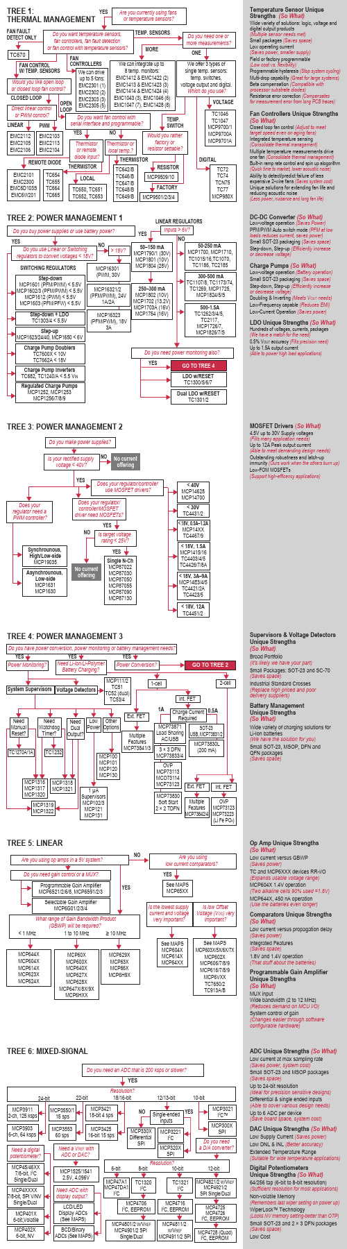
TREE 3: POWER MANAGEMENT 2Supervisors & Voltage Detectors Unique Strengths (So What)Broad Portfolio(It's likely we have your part)Small Packages: SOT-23 and SC-70 (Saves space)Industrial Standard Crosses (Replace high priced and poor delivery suppliers)Battery Management Unique Strengths (So What)Wide variety of charging solutions for Li-Ion batteries(We have the solution for you)Small SOT-23, MSOP, DFN and QFN packages (Saves space)DC-DC Converter (So What)Low-voltage operation (Saves Power)PFM/PWM Auto switch mode (PFM at low loads reduces current, saves power)Small SOT-23 packaging (Saves space)Step-down, Step-up (Efficiently increase or decrease voltage) Charge Pumps (So What)Low-voltage operation (Battery operation)Small SOT-23 packaging (Saves space)Step-down, Step-up (Efficiently increase or decrease voltage)Doubling & Inverting (Meets V OUT needs) Low-Frequency capable (Reduces EMI)Low-Current Operation (Saves power)LDO Unique Strengths (So What)Hundreds of voltages, currents, packages (We have a match for the need)0.5% V OUT accuracy (Fills precision need)Up to 1.5A output current(Able to power high load applications)Op Amp Unique Strengths (So What)Low current versus GBWP (Saves power)TC and MCP6XXX devices RR-I/O (Expands usable voltage range)MCP604X 1.4V operation(Two alkaline cells 90% used =1.8V)MCP644X, 450 nA operation (Use the batteries even longer)Comparators Unique Strengths (So What)Low current versus propagation delay (Saves power)Integrated Features (Saves space)1.8V and 1.4V operation (That stuff about the batteries)Programmable Gain Amplifier Unique Strengths (So What)MUX inputWide bandwidth (2 to 12 MHz) (Reduces demand on MCU I/O)System control of gain(Changes easier through software configurable hardware)TREE 5: LINEARTemperature Sensor Unique Strengths (So What)Wide variety of solutions: logic, voltage and digital output products(Multiple sensor needs met)Small packages (Saves space)Low operating current(Saves power, smaller supply)Field or factory programmable (Low cost vs. flexibility)Programmable hysteresis (Stop system cycling)Multi-drop capability (Great for large systems)Beta compensation (Compatible with processor substrate diodes)Resistance error correction (Compensates for measurement error from long PCB traces)Fan Controllers Unique Strengths (So What)Closed loop fan control (Adjust to meet target speed even on aging fans)Integrated temperature sensing (Consolidate thermal management)Multiple temperature measurements drive one fan (Consolidate thermal management)Built-in ramp rate control and spin up alogorithm (Quick time to market, lower acoustic noise)Ability to detect/predict failure of less expensive 2-wire fans (Saves system cost)Unique solutions for extending fan life and reducing acoustic noise(Less power, nuisance and long fan life)TREE 6: MIXED-SIGNALADC Unique Strengths (So What)Low current at max sampling rate (Saves power, system cost)Small SOT-23 and MSOP packages (Saves space)Up to 24-bit resolution(Ideal for precision sensitive designs)Differential & single ended inputs (Able to cover various design needs)Up to 6 ADC per device(Save board space, system cost)DAC Unique Strengths (So What)Low Supply Current (Saves power)Low DNL & INL (Better accuracy)Extended Temperature Range(Suitable for wide temperature applications)Digital Potentiometers Unique Strengths (So What)64/256 tap (6-bit to 8-bit resolution)(Sufficient resolution for most applications)Non-volatile Memory(Remembers last wiper setting on power up)WiperLock™ Technology(Locks NV memory setting-better than OTP)Small SOT-23 and 2 × 3 DFN packages (Saves space)Low CostMOSFET Drivers (So What)4.5V up to 30V Supply voltages (Fills many application needs)Up to 12A Peak output current(Able to meet demanding design needs)Outstanding robustness and latch-upi mmunity (Ours work when the others burn up)Low-FOM MOSFETs(Support high-efficency applications)TREE 4: POWER MANAGEMENT 3LIN Unique Strengths(So What)Compliant with LIN Bus Specs 1.3, 2.0, 2.1 andSAE J2602 (Allows for reliable interoperability)High EMI Low EME (Meets OEM requirements)On-board V REG available(Saves space, allows for MCU V CC flexibility)CAN Unique Strengths(So What)Simple SPI CAN controller is an easy way toadd CAN Ports (Short design cycles)High speed transceiver meets ISO-11898 (Drop inreplacement for industry standard transceivers)Low-cost, easy-to-use development tools(Tools easy to buy/use, quick design)I/O Expanders Unique Strengths(So What)Configurable inputs (interrupt configuration flexibility)Interrupt on pin change, or change fromregister default (interrupt source flexibility)Can disable automatic address incrementingwhen accessing the device(allows continual access to the port)The 16-bit devices can operate in 8-bit or 16-bitmode (easy to interface to 8-bit or 16-bit MCUs)IrDA Unique Strengths (So What)IrDA protocol handler embedded on chip(Complex design issue solved)Low cost developer's kit available to assistInfrared design-in (Quick design cycle)Small, cost-effective way of replacing serial links(No more wires)Enables system to wirelessly communicatewith PDA (Wireless connectivity solution) TREE 8: INTERFACEAnalog & InterfaceQuestion TreesAnalog & Interface Development ToolsDemonstration Boards, Evaluation Kits and AccessoriesAnalog & Interface LiteratureADM00313EV: MCP73830L 2 × 2 TDFN Evaluation BoardADM00352: MCP16301 High Voltage Buck Converter 600 mA Demonstration BoardADM00360: MCP16301 High Voltage Buck Coverter 300 mA D2PAK Demonstration BoardADM00427: MCP16323 Evaluation Board (Supports MCP16321 and MCP16322)ARD00386: MCP1640 12V/50 mA Two Cells Input Boost Converter Reference DesignMCP1252DM-BKLT: MCP1252 Charge Pump Backlight Demonstration BoardMCP1256/7/8/9EV: MCP1256/7/8/9 Charge Pump Evaluation BoardMCP1630RD-LIC1: MCP1630 Li-Ion Multi-Bay Battery Charger Reference DesignMCP1630DM-NMC1: MCP1630 NiMH Battery Charger Demonstration BoardMCP1640EV-SBC: MCP1640 Sync Boost Converter Evaluation BoardMCP1640RD-4ABC: MCP1640 Single Quad-A Battery Boost Converter Reference DesignMCP1650DM-LED1: MCP165X 3W White LED Demonstration BoardMCP1726EV: MCP1726 LDO Evaluation BoardMCP73831EV: MCP73831 Evaluation KitMCP7383XEV: MCP73837/8 AC/USB Dual Input Battery Charger Evaluation BoardMCP7383XRD-PPM: MCP7383X Li-Ion System Power Path Management Reference DesignMCP7384XEV: MCP7384X Li-Ion Battery Chager Evaluation BoardMCP73871EV: MCP73871 Load Sharing Li-Ion Battery Charger Evaluation BoardTC1016/17EV: TC1016/17 LDO Evaluation BoardVSUPEV: SOT-23-3 Voltage Supervisor Evaluation BoardPowerManagementThermalManagementMCP9700DM-PCTL: MCP9700 Thermal Sensor PICtail Demonstration BoardMCP9800DM-PCTL: MCP9800 Thermal Sensor PICtail Demonstration BoardTC72DM-PICTL: TC72 Digital Temperature Sensor PICtail Demonstration BoardTC74DEMO: TC74 Serial Daughter Thermal Sensor Demonstration BoardTC1047ADM-PCTL: TC1047A Temperature-to-Voltage Converter PICtail™ Demonstration BoardSerial GPIODM-KPLCD: GPIO Expander Keypad and LCD Demonstration BoardMCP23X17: MCP23X17 16-bit GPIO Expander Evaluation BoardInterface MCP2515DM-BM: MCP2515 CAN Bus Monitor Demonstration BoardMCP2515DM-PTPLS: MCP2515 PICtail™ Plus Daughter BoardMCP2515DM-PCTL: MCP2515 CAN Controller PICtail Demonstration BoardMCP215XDM: MCP215X/40 Data Logger Demonstration BoardMCP2140DM-TMPSNS: MCP2140 IrDA® Wireless Temp Demonstration BoardLinear ADM00375: MCP6H04 Evaluation BoardARD00354: MCP6N11 Wheatstone Bridge Reference DesignMCP651EV-VOS: MCP651 Input Offset Evaluation BoardMCP661DM-LD: MCP661 Line Driver Demo BoardMCP6S22DM-PCTL: MCP6S22 PGA PICtail Demonstration BoardMCP6S2XEV: MCP6S2X PGA Evaluation BoardMCP6SX2DM-PCTLPD: MCP6SX2 PGA Photodiode PICtail Demonstration BoardMCP6SX2DM-PCTLTH: MCP6SX2-PGA Thermistor PICtail Demonstration BoardMCP6V01RD-TCPL: MCP6V01 Thermocouple Auto-Zero Ref DesignMCP6XXXDM-FLTR: Active Filter Demo BoardPIC16F690DM-PCTLHS: Humidity Sensor PICtail Demonstration BoardMixed-Signal MCP3221 DM-PCTL: MCP3221 12-bit A/D PICtail Demonstration BoardMCP3421DM-BFG: MCP3421 Battery Fuel Gauge Demonstration BoardMCP3551DM-PCTL: MCP3551 PICtail Demonstration BoardMCP355XDM-TAS: MCP355X Tiny Application Sensor Demonstration BoardMCP355XDV-MS1: MCP3551 Sensor Demonstration BoardMCP402XEV: MCP402X Digital Potentiometer Evaluation BoardMCP4725EV: MCP4725, 12-bit Non-Volatile DAC Evaluation Board (Preferred One)MCP4725DM-PTPLS: MCP4725, 12-bit Non-Volatile DAC PICtail Demonstration BoardADM00398: MCP3911 ADC Evaluation Board for 16-bit MicrocontrollersCorporate Microchip Product Line Card - DS00890Brochures Analog and Interface Product Selector Guide - DS21060Low Cost Development Tools Solutions Guide - DS51560Analog and Interface Guide (Volume 1) - DS00924Analog and Interface Guide (Volume 2) - DS21975Cards Analog Highlights Card - DS21972Microchip Op Amp Discovery Card - DS21947Analog & Interface Question Trees - DS21728Mirochip SAR and Delta-Sigma ACD Discovery Card - DS22101Software Tools MAPS - Microchip Advanced Product SelectorAnalog & Interface Treelink Products PresentationDesign Guides Analog-to-Digital Converter Design Guide - DS21841Digital Potentiometers Design Guide - DS22017Programmable Gain Amplifiers (PGAs), Operational Amplifiersand Comparators Design Guide - DS21861Interface Products Design Guide - DS21883Signal Chain Design Guide - DS21825Power Solutions Design Guide - DS21913Temperature Sensor Design Guide - DS21895Voltage Supervisors Design Guide - DS51548DS21728JPowerManagementLDO & SwitchingRegulatorsCharge PumpDC/DC ConvertersPower MOSFETDriversPWM ControllersSystem SupervisorsVoltage DetectorsVoltage ReferencesLi-Ion/Li-PolymerBattery ChargersUSB Port PowerControllersMixed-SignalA/D ConverterFamiliesDigitalPotentiometersD/A ConvertersV/F and F/VConvertersEnergyMeasurement ICsCurrent/DC PowerMeasurement ICsInterfaceCAN PeripheralsInfraredPeripheralsLIN TransceiversSerial PeripheralsEthernet ControllersUSB PeripheralLinearOp AmpsInstrumentationAmpsProgrammableGain AmplifiersComparatorsSafety & SecurityPhotoelectricSmoke DetectorsIonization SmokeDetectorsIonization SmokeDetector Front EndsPiezoelectricHorn DriversThermalManagementTemperatureSensorsFan Control& HarwareManagementMotor DriveStepper and DC3Ф BrushlessDC Motor DriverTREE 7: MOTOR DRIVE Stepper Unique Strenghts(So What)Industrial standard footprint(Footprint compatible to industrial leaders)Perfect PIC® MCU companion chip(Solid field support)Micro-stepping ready(Enhanced performance)Integration protections(Simplify software development)3-Phase BLDC Unique Strengths(So What)Full-wave sinusoidal(Quiet operation, low mechanical vibration)Sensorless operation (Minimum externalcomponents, no software required)Thin form factor(Fits space concerned applications)Information subject to change. The Microchip name and logo, the Microchip logo, dsPIC, PIC are registered trademarks and MiWi, PICtail and ZENA are trademarks ofMicrochip Technology Incorporated in the U.S.A. and other countries. All other trademarks mentioned herein are property of their respective companies.© 2012, Microchip Technology Incorporated. All Rights Reserved.。
Moxa MPC-2070系列7英寸面板计算机说明书

P/N: 1802020700011 *1802020700011*MPC-2070 SeriesQuick Installation GuideEdition 2.0, October 2018Technical Support Contact Information/supportMoxa Americas:Toll-free: 1-888-669-2872 Tel: 1-714-528-6777 Fax: 1-714-528-6778 Moxa China (Shanghai office): Toll-free: 800-820-5036 Tel: +86-21-5258-9955 Fax: +86-21-5258-5505 Moxa Europe:Tel: +49-89-3 70 03 99-0 Fax: +49-89-3 70 03 99-99 Moxa Asia-Pacific:Tel: +886-2-8919-1230 Fax: +886-2-8919-1231 Moxa India:Tel: +91-80-4172-9088 Fax: +91-80-4132-10452018 Moxa Inc. All rights reserved.OverviewThe MPC-2070 7-inch panel computers with Intel® Atom™ E3800 series processors deliver a reliable and durable platform of wide versatility for use in industrial environments. With two software selectableRS-232/422/485 serial ports and two gigabit Ethernet LAN ports, the MPC-2070 panel computers support a wide variety of serial interfaces as well as high-speed IT communications, all with native network redundancy.Package ChecklistBefore installing the MPC-2070, verify that the package contains the following items:• 1 MPC-2070 panel computer• 1 2-pin terminal block for DC power input• 1 10-pin terminal block for DIO• 1 2-pin terminal block for remote power switch• 6 panel mounting screws•Quick installation guide (printed)•Warranty cardNOTE: Please notify your sales representative if any of the above items are missing or damaged.Hardware InstallationFront ViewBottom ViewA panel-mounting kit consisting of 6 mounting units is provided in the MPC-2070 package. For details on the dimensions and the cabinet space required to panel mount the MPC-2070, refer to the following illustration:To install the panel-mounting kit on the MPC-2070, place the mounting units in the holes provided on the rear panel and push the units to the left as shown in the illustration below:Use a torque of 4Kgf-cm to secure the mounting screws to fasten the panel-mounting kit onto the wall.The MPC-2070 is provided with VESA-mounting holes on the back panel, which you can use directly without the need for an adapter. Thedimension of the VESA mounting area is 50 x 75 mm. You will require four M4 x 6 mm screws to VESA mount the MPC-2070.Display-Control ButtonsThe MPC-2070 is provided with two display-control buttons on the right panel.The usage of the display-control buttons is described in the following table:Symbol and NameUsageFunctionPower Press• Power on• Enter Seep or Hibernation mode • Wake upNOTE: You can change the function of the power button in the OS settings menuPress andhold for 4 secondsPower offSymbol and Name Usage FunctionBrightness + Press Manually increase the brightness ofthe panelBrightness -PressManually decrease the brightness of the panelConnector DescriptionDC Power InputThe MPC-2070 uses a DC power input. To connect the power source to the 2-pinterminal block, use a 60 W power adapter. The terminal block is available in the accessories package. The DC pin assignments are show in the figure.Serial PortsThe MPC-2070 offers two software-selectable RS-232/422/485 serial ports over a DB9 connector. The pin assignments for the ports are shown in the table below:Pin RS-232RS-422RS-485 (4-wire) RS-485 (2-wire)1 DCD TxDA(-) TxDA(-) –2 RxD TxDB(+) TxDB(+) –3 TxD RxDB(+) RxDB(+) DataB(+)4 DTR RxDA(-) RxDA(-) DataA(-)5 GND GND GND GND6 DSR – – –7 RTS – – – 8CTS–––Ethernet PortsThe pin assignments for the two Fast Ethernet 100/1000 Mbps RJ45 ports are shown in the following table:Pin 100 Mbps 1000 Mbps 1 ETx+ TRD(0)+ 2 ETx- TRD(0)- 3 ERx+ TRD(1)+ 4 –TRD(2)+ 5 – TRD(2)- 6 ERx- TRD(1)- 7 – TRD(3)+ 8 – TRD(3)-The LEDs on the LAN ports indicate the following: LAN 1/LAN 2 (indicators on the connectors) Green 100 Mbps Ethernet modeYellow 1000 Mbps (Gigabit) Ethernet mode Off No activity / 10 Mbps Ethernet modeUSB PortsTwo USB 2.0 ports are available on the bottom panel. Use these ports to connect mass storage drives and other peripherals. DIO PortThe MPC-2070 is provided with a DIO port, which is a 10-pin terminal block that includes 4 DIs and 4 DOs as illustrated in the diagram.Installing a CFast or SD CardMPC-2070 provides two storage options—CFast and SD card. The storage slots are located on the left panel. You can install the OS on the CFast card and save your data into the SD card. For a list of compatible CFast models, check the MPC-2070 component compatibility report available on Moxa’s website.To install the storage devices, do the following:1. Remove the 2 screws holding the storage-slot cover to the MPC-2070.2. Insert the CFast or SD card into the slot using the push-pushmechanism.3. Reattach the cover and secure it with screws. Real Time ClockThe real time clock (RTC) is powered by a lithium battery. We strongly recommend that you do not replace the lithium battery without help from a qualified Moxa support engineer. If you need to change the battery, contact the Moxa RMA service team. The contact details are available at: /rma/about_rma.aspx .Powering On/Off the MPC-2070Connect a Terminal Block to Power Jack Converter to the MPC-2070 terminal block and connect a 60 W power adapter to the converter. Supply power through the power adapter. After you have connected a power source, press the Power button to turn the computer on. It takes about 10 to 30 seconds for the system to boot up.To power off the MPC-2070, we recommend using the "shut down" function provided by the OS installed on the MPC. If you use the Power button, you may enter one of the following states depending on the power management settings in the OS: standby, hibernation, or system shutdown mode. If you encounter problems, you can press and hold the Power button for 4 seconds to force a hard shutdown of the system. Grounding the MPC-2070 SeriesProper grounding and wire routing help to limit the effects of noise from electromagnetic interference (EMI). Run the ground connection from the ground screw to the grounding surface prior to connecting the power source.Label Drawing InformationTrade Mark:Model: Nomenclature for models MPC-2070 andMPC-2120 series:MPC-2070 -xx -yyyyyyyyyyI II IIII – Screen size:MPC-2070: 7” panelMPC-2120: 12” panelII – CPU typeE2: Intel® Atom™ Processor E3826 1.46 GHzE4: Intel® Atom™ Processor E3845 1.91 GHz(MPC-2120 series only)III – Marketing purpose0 to 9, A to Z, dash, blank, (,), or any character formarketing purpose.Rating: For model MPC-2070-E2-yyyyyyyyy 12-24 Vdc,2.5 A or 24 Vdc, 1.25 A or 12 Vdc, 2.5 AFor model MPC-2120-xx-yyyyyyyyy 12-24 Vdc,3.5 A or 24 Vdc, 1.75 A or 12 Vdc, 3.5 AS/NATEX information:II 3 GDEMKO 18 ATEX 2048XEx nA IIC T4 GcAmbient Range:-40°C ≤ Ta ≤ +70°C, or -40°C ≤ Tamb ≤ +70°CRated Cable Temp ≥ 107 °CIECEx Certificate no.: IECEx UL 18.0064XAddress of manufacturer: FI.4, No.135, Lane 235, Baoqiao Rd. Xindian Dist., New Taipei City, TaiwanCondition of Use•Subject devices are intended for use in an area of not more than pollution degree 2 in accordance with IEC/EN 60664-1.•Subject devices are intended for use in low risk of mechanical impact environments.•The equipment shall be installed (panel mount) to an enclosure that provides a degree of protection not less than IP54 in accordance with IEC/EN 60079-15, and accessible only by use of a tool. Hazardous Location Standard•EN 60079-0:2012 + A11:2013•EN 60079-15: 2010•IEC 60079-0 6th Edition•IEC 60079-15 4th Edition。
ASROCK 770 Extreme3 说明书

產品摘要- 支持6核心处理器- 华擎DuraCap电容(2.5倍更长的使用寿命), 100% 日本原装高品质高传导固态电容 - 支持高达140W的CPU- 通过ACC(高级时钟校准)功能支持AMD OverDrive™ 系统调节- 支持双通道DDR3 1600内存- 2 x SATA3 6.0 Gb/s 接口, 1 x USB 3.0 接口, 1 x eSATAII 接口, PCIE 千兆网卡- 支持华擎 Instant Boot, Instant Flash, 华擎超频 调节器, 智能型能源节约器, OC DNA- 7.1声道高保真音频,支持内容保护功能(ALC892 音频编码解码器),支持优质蓝光音效 - 支持 ErP/EuP- 附赠 : CyberLink DVD 套件 - OEM 与试用版; Creative Sound Blaster X-Fi MB - 试用版規格更改時恕不預先通知 品牌和產品名稱歸各自公司所有。
不保證任何配置与產品實物規格相同。
詳細規格中央處理器芯片內存擴充插槽音效网絡背板I/O板載接口SATA3USB 3.0BIOS 特性支持光盤獨家功能附件規格尺寸認證硬件監控操作系統- ATX 规格: 12.0-in x 8.2-in, 30.5 cm x 20.8 cm- 全固态电容设计 (100%日本原装高品质高传导固态电容)- 支持 Socket AM3 处理器:AMD Phenom II X4 / X3 / X2 (除了 920 / 940) / Athlon II X4 / X3 / X2 / Sempron 处理器- 支持六核心处理器 - 支持高达140W的CPU- 通过ACC(高级时钟校准)功能支持AMD OverDrive™ 系统调节- AMD LIVE! Ready- 支持AMD Cool 'n' Quiet降温静音技术- 前端总线2600 MHz(5.2 GT/s)- 支持自由超频技术- 支持Hyper-Transport 3.0 (HT 3.0)技术- 北桥: AMD 770- 南桥: AMD SB710- 双通道DDR3内存技术- 4 x DDR3 内存插槽- 支持DDR3 1600/1333/1066/800 non-ECC, un-buffered内存- 系统内存最大容量: 16GB- 1 x PCI Express 2.0 x 16 插槽 (蓝色: x 16)- 2 x PCI Express 2.0 x 1 插槽- 3 x PCI 插槽- 7.1声道高保真音频,支持内容保护功能(ALC892音频编码 解码器)- 支持优质蓝光音效- PCIE x 1 千兆网卡10/100/1000 Mb/s - Realtek RTL8111DL- 支持网络唤醒功能(Wake-On-LAN)- 4 x SATAII接口(3.0 Gb/s),支持RAID(RAID 0,RAID 1, RAID 10 和JBOD), NCQ, AHCI和“热插拔”功能- 2 x SATA3接口(6.0 Gb/s)- 1 x ATA133 IDE接口(支持2 x IDE设备)- 1 x 软驱接口- 1 x 红外线接针- 1 x COM端口接针- 1 x HDMI_SPDIF 接头- 1 x 电源 LED 接针- CPU/机箱/电源风扇接口- 24针ATX电源接口- 8针12V电源接口- CD输入接针- 前面板音频接口- 3 x USB 2.0接针(支持6 x USB 2.0接口)- 8Mb AMI Legal BIOS - 支持“即插即用”- 符合ACPI 1.1,支持唤醒与自动开机(Wake Up Events)- 支持免跳线- 支持SMBIOS 2.3.1- CPU VID电压多功能调节器- 由 Marvell SE9123 支持的 2 组 SATA 6.0Gb/s 端口, 可支持硬件 NCQ、AHCI 与 热插拔功能- 由 Fresco FL1000G 支持的一个 USB 3.0 端口,支持 USB 1.0/2.0/3.0,最高速度可达 5Gb/s- 驱动程序, 应用软件, 杀毒软件 (试用版),华擎软件套装(CyberLink DVD 套件 - OEM 与试用版; Creative Sound Blaster X-Fi MB - 试用版)- 华擎超频调节器- 智能型能源节约器- Instant Boot- 华擎 Instant Flash - 华擎 OC DNA- Hybrid Booster(安心超频技术): - CPU频率无段调节- ASRock U-COP(华擎通用CPU过热保护技术) - Boot Failure Guard (B.F.G.,启动失败恢复技术)- 支持Microsoft Windows 7 / 7 64-bit / Vista / Vista 64-bit / XP / XP Media Center / XP 64-bit- FCC, CE, WHQL- 支持 ErP/EuP(需要搭配支持 ErP/EuP 的电源供应器)- 1 x 华擎SLI_Bridge_2S桥接卡- 快速安装指南,支持光盘,I/O挡板- 软驱/ATA 133排线- 2 x SATA数据线(选购)- 1 x SATA 1对1电源线(选购)- CPU温度检测- 机箱温度检测- CPU/机箱/电源风扇转速计- CPU静音风扇- 电压实时监控:+12V,+5V,+3.3V,核心电压I/O面板- 1 x PS/2鼠标接口- 1 x PS/2键盘接口- 1 x 同轴SPDIF数字音频输出端口- 1 x 光纤SPDIF数字音频输出端口- 5 x USB 2.0接口- 1 x eSATAII 接口- 1 x USB 3.0接口- 1 x RJ-45 网卡接口LED指示灯(ACT/LINK LED和SPEED LED)- HD音频插孔:侧置喇叭/后置喇叭/中置/低音/线性输入/ 前置喇叭/麦克风USB3.0,全球使用最普遍的电脑外围接口再次迎来了重大革新,以适应目前人们对连接带宽越来越高的要求 。
台式 三屏16键操作手册
数字键:0~9,在计数和检重状态时输入数据用 功能键: 1)取消键:取消当前输入,取消当前操作 2)个数设定键:用于待计数产品单重未知的过程 3)警示:设定警示值,包括个数和质量 4)确定键:对输入的个数或者单重确定并进行采样 5)单重设定键:用于待计数产品单重已知的过程 6)去皮:在置零范围外将当前秤盘上的物质作为皮重处
设的报警范围内的话,单重显示“—PASS—”,并又警示声。 注意: 设定的上限值必须大于下限值,否则在输入下限值之后,按【警 示】不能退出警示预设操作,总重窗显示“—H—” ,提示您重新 输入上下限值。
/
请不要加载超过天平最大量程的物品,当显示“—OL—” 并有蜂鸣器叫时请立即卸下天平秤盘上的物品,避免传感 器受损。 8 5
主要功能及特点
1.LCD显示,带LED背光,清晰易读 2.具有单重设定和个数设定两种取样方式 3.具有检重警示功能 警 示
按键功能说明
按键图
个数 设定
清 除
5
4
3
2
1
操作之前
1.打开电源时,秤盘上请勿放置任何东西 2.如长期不使用,请擦拭干净,放入干燥剂后用塑料袋包好 确 定
单重 设 定
去 皮
ቤተ መጻሕፍቲ ባይዱ
0
9
8
存放和运输条件 请勿将仪器放置于温度过高或过低、易碰
撞、剧烈震动、湿度较大、气流较大的环境中。 — — —
境中使用 不要将仪器置于由于门窗打开而形成空气对流的通道上 在测量时避免出现剧烈震动现象 采用保护措施,防止仪器遭受腐蚀性气体的侵蚀 不要将仪器长期放置在潮湿的环境中 严禁撞击、重压(勿超过其最大称量) 长期不使用时,请将干电池取出。可充电电池每三个月充电一 次,以保护电池 如何使台秤适应温度变化: 不要将仪器长期置于湿度较大的环境里。当把一台放在较低环境温度 中的仪器搬到环境温度较高的工作间后, 应将仪器在工作间里静放约 2 小时,并切断电源。2 小时后,接通电源,仪器内部与外部环境之间持
仪器型号:H17073 MAX 温度计说明书
DP41-TCHigh Performance Temperature IndicatorThe information contained in this document is believed to be correct, but OMEGA accepts no liability for any errors it contains, and reserves the right to alter specifications without notice.U.S.A. Omega Engineering, Inc.Headquarters: Toll-Free: 1-800-826-6342 (USA & Canada only)Customer Service: 1-800-622-2378 (USA & Canada only) Engineering Service: 1-800-872-9436 (USA & Canada only) Tel: (203) 359-1660 Fax: (203) 359-7700 e-mail:**************For Other Locations Visit /worldwideFor complete product manual:/manuals/manualpdf/M1296.pdfWARRANTY/DISCLAIMEROMEGA ENGINEERING, INC. warrants this unit to be free of defects in materials and workmanship for a period of 61 months from date of purchase. OMEGA’s WARRANTY adds an additional one (1) month grace period to the normal five (5) year product warranty to cover handling and shipping time. This ensures that OMEGA’s customers receive maximum coverage on each product.If the unit malfunctions, it must be returned to the factory for evaluation. OMEGA’s Customer S ervice Department will issue an Authorized Return (AR) number immediately upon phone or written request. Upon examination by OMEGA, if the unit is found to be defective, it will be repaired or replaced at no charge. OMEGA’s WARRANTY does not apply to defects resulting from any action of the purchaser, including but not limited to mishandling, improper interfacing, operation outside of design limits, improper repair, or unauthorized modification. This WARRANTY is VOID if the unit shows evidence of having been tampered with or shows evidence of having been damaged as a result of excessive corrosion; or current, heat, moisture or vibration; improper specification; misapplication; misuse or other operating conditions outside of OMEGA’s control. Components in which wear is not warranted, include but are not limited to contact points, fuses, and triacs.OMEGA is pleased to offer suggestions on the use of its various products. However, OMEGA neither assumes responsibility for any omissions or errors nor assumes liability for any damages that result from the use if its products in accordance with information provided by OMEGA, either verbal or written. OMEGA warrants only that the parts manufactured by the company will be as specified and free of defects. OMEGA MAKES NO OTHER W ARRANTIES OR REPRESENTATIONS OF ANY KIND W HATSOEVER, EXPRESSED OR IMPLIED, EXCEPT THAT OF TITLE, AND ALL IMPLIED W ARRANTIES INCLUDING ANY W ARRANTY OF MERCHANTABILITY AND FITNESS FOR A PARTICULAR PURPOSE ARE HEREBY DISCLAIMED. LIMITATION OF LIABILITY: The remedies of purchaser set forth herein are exclusive, and the total liability of OMEGA with respect to this order, whether based on contract, warranty, negligence, indemnification, strict liability or otherwise, shall not exceed the purchase price of the component upon which liability is based. In no event shall OMEGA be liable for consequential, incidental or special damages.CONDITIONS: Equipment sold by OMEGA is not intended to be used, nor shall it be used: (1) as a “Basic Component” under 10 CFR 21 (NRC), used in or with any nuclear installation or activity; or (2) in medical applications or used on humans. S hould any Product(s) be used in or with any nuclear installation or activity, medical application, used on humans, or misused in any way, OMEGA assumes no responsibility as set forth in our basic WARRANTY/DIS CLAIMER language, and, additionally, purchaser will indemnify OMEGA and hold OMEGA harmless from any liability or damage whatsoever arising out of the use of the Product(s) in such a manner.RETURN REQUESTS/INQUIRIESDirect all warranty and repair requests/inquiries to the OMEGA Customer Service Department. BEFORE RETURNING ANY PRODUCT(S) TO OMEGA, PURCHAS ER MUS T OBTAIN AN AUTHORIZED RETURN (AR) NUMBER FROM OMEGA’S CUS TOMER S ERVICE DEPARTMENT (IN ORDER TO AVOID PROCESSING DELAYS). The assigned AR number should then be marked on the outside of the return package and on any correspondence.FOR WARRANTY RETURNS, please have the followinginformation available BEFORE contacting OMEGA:1.Purchase Order number underwhich the product was PURCHA S ED,2.Model and serial number ofthe product under warranty, and 3.Repair instructions and/orspecific problems relative to the product.FOR NON-WARRANTY REPAIRS, consult OMEGA for current repair charges. Have the following information available BEFORE contacting OMEGA:1.Purchase Order number to coverthe COST of the repair or calibration,2. 3. Model and serial number of theproduct, and R epair instructions and/or specificproblems relative to the product.OMEGA’s policy is to make running changes, not model changes, whenever an improvement is possible. This affords our customers the latest in technology and engineering.OMEGA is a trademark of OMEGA ENGINEERING, INC.© Copyright 2018 OMEGA ENGINEERING, INC. All rights reserved. This document may not be copied, photocopied, reproduced, translated, or reduced to any electronic medium or machine-readable form, in whole or in part, without the prior written consent of OMEGA ENGINEERING, INC.MQS 1296/0818***********************Servicing North America:800 Connecticut Ave. Suite 5N01Norwalk, CT 06854Using This Quick Start ManualUse this Quick Start Manual to get your Temperature Indicator, when used with a Thermocouple, up and running right out of the box. To do this you:•connect ac power•connect the Thermocouple•configure the unit–specify Thermocouple type–set degrees to C or F–set decimal point positionThe latest complete Communication andOperational Manual as well as free Softwareare available at /software. Before You BeginYou should have the following parts:•Meter•Panel-mounting gaskets•ac Power Connector (orange -P1), Input Connectors (2)(grey -P3 and P9), and rearprotective cover (mounted)with green Cold JunctionCompensation Board (rightside).In addition to the unit and related parts, you will need the following items to set up your unit:•ac power, as listed on meter’s Product/ID label •Thermocouple•1/8” flat blade screwdriver•1/8” Phillips head screwdriverSafety Consideration234SAFETY:•Do not exceed voltage rating on the label located on thetop of the instrument housing.•Always disconnect power before changing signal andpower connections.•Do not use this instrument on a work bench withoutits case for safety reasons.•Do not operate this instrument in flammable or explosiveatmospheres.•Do not expose this instrument to rain or moisture.EMC:•Whenever EMC is an issue, always use shielded cables.•Never run signal and power wires in the same conduit.••Use signal wire connections with twisted-pair cables.Install Ferrite Bead(s) on signal wire close to theinstrument if EMC problems persist.Mount the Unit1.Cut a panel2.3.4.Position the unit inthe opening,making sure thefront bezel/ gasketis flush with thepanel.From the rear ofthe panel surface.The panel should now be sandwiched between the bezel-backed gasket in front and the sleeve in back.5.Replace the thumbnuts that secure the sleeve tabsto the case.Connect ac Poweropening using theshown to the right.1.Remove the rear protective cover and set it aside.Thecover is secured with a Phillips-head screw.2.Locate connector P1 on the bottom-left-rear of the unit.The connector has three screw-down terminals (seebelow).EXTERNAL FUSE WIRED115 Vac IEC127-2/III, 125mA, 250V (Time-L a g)or UL Slow-Blow, 125mA, 250V230 Vac IEC127-2/III, 63mA, 250V (Time-L a g) orUL Slow-Blow, 63mA, 250V61010:2010 Electrical Safety Requirements for ElectricalEquipment for Measurement, Control and Laboratory. Thedevice has no power-on switch. Installations must include aswitch or circuit breaker that is compliant to IEC 947-1 and947-3. It must be suitably located to be easily reached andmarked as the disconnecting devise for the equipment.Use copper conductors only, minimum 20 AWG,UL Rated, for power connection. Insulation must be rated forat least 85C and 600V.。
AC300说明书
目录1 引言 (4)1.1 编写目的 (4)1.2 注意事项 (4)2 启动 (4)3 初始界面 (4)4 应用程序结构与模块 (6)4.1 用户管理 (9)4.1.1 用户登记 (9)指纹登记 (13)ID(Mifare)卡登记 (13)原声录制 (14)拍照 (15)4.1.2 删除登记记录 (17)4.2 设置 (18)4.2.1基本设置 (18)时间设置 (18)语言设置 (18)语音提示 (18)音量调节 (19)按键音 (19)报警设置 (19)4.2.2 高级设置 (19)4.2.2.1 验证界面设置 (19)是否实时拍照 (19)是否显示照片 (19)实时指纹显示设置 (19)4.2.2.2删除全部记录 (19)4.2.2.3 删除全部登记数据 (20)4.2.2.4 恢复出厂设置 (20)4.2.2.5 固件升级 (20)4.2.2.6 夏令时设置: (20)4.2.2.7 功能键设置 (20)4.2.3 电源管理 (20)定时开机 (21)定时关机 (21)定时休眠 (21)响铃设置 (21)空闲设置 (21)锁闭关机键 (21)定时状态转换 (21)4.2.4 通讯设置 (22)机器编号 (22)RS232 (22)RS485 (22)波特率 (22)以太网 (22)IP地址 (22)子网掩码 (22)网关地址 (22)连接密码 (23)动态IP分配 (23)后台地址 (23)4.2.5 记录设置 (23)管理记录警告(报警) (23)验证记录警告(报警) (23)重复确认时间 (23)4.2.6 自动检测 (23)4.3门禁功能设置 (24)4.3.1 时间段设置 (24)4.3.2 分组功能设置 (25)4.3.3 用户门禁设置 (25)4.3.4 开锁组合设置 (26)开锁组合基本设置 (26)开锁组合设置 (26)4.3.5 锁驱动时长 (28)4.3.6 门磁延时 (28)4.3.7 门磁开关设置 (28)4.3.8 胁迫报警设置 (28)胁迫指纹管理 (28)验密码报警 (28)按键求助 (28)报警延迟 (29)4.3.9 错按报警 (29)4.3.10 反潜功能设置 (29)4.3.11 绑定ID (29)4.4 U盘管理 (29)4.5解除报警 (29)4.6系统信息 (30)4.6.1 用户登记数 (30)4.6.2 指纹登记数 (30)4.6.3 验证记录数 (30)4.6.4 管理记录数 (30)4.6.5 已用内存 (30)4.6.6 剩余容量 (30)4.6.7 设备信息 (30)4.7数据查询 (31)验证记录查询 (31)管理记录查询 (31)用户登记查询 (31)5外接端口连接方式 (31)5.1 外接端口总体描述 (31)5.2 连接说明 (32)5.2.1 RS232连接 (32)5.2.2 RS485连接 (32)5.2.3 出门开关连接 (33)5.2.4 门磁连接 (34)5.2.5 报警连接 (34)5.2.6 电锁连接 (35)5.2.7 电铃连接 (36)5.2.8 指纹读头连接 (37)6组网方式 (37)6.1 分体机组网方式 (38)6.2 一体机组网方式 (38)6.3 指纹读头组网方式 (38)7 终端设备组网调线方式说明 (39)7.1分体机调线连接方式图 (40)7.2一体机调线连接方式图 (41)8 控制器使用说明 (41)8.1 控制器外接端口图说明 (42)8.2 控制器连接说明 (42)8.2.1 出门开关连接 (42)8.2.2 门磁连接 (43)8.2.3 报警器连接 (43)8.2.4 电锁连接 (44)8.2.5 电铃连接 (46)9 基本概念与说明 (47)误判 (47)拒判 (47)权限级别 (47)状态键 (47)消息通知 (47)主从机 (48)夏令时(时区设置) (48)1 引言1.1 编写目的用户使用说明书.1.2 注意事项本考勤机不可阳光直射或强烈阳光下工作。
宝云兴业科贸 专业空气测计仪器 产品说明书
北京宝云兴业科贸有限公司成立于1998 年,自成立伊始,就秉持着“诚信、执着、创新、快速”的经营理念。
公司以国家相关标准为依据,引进国际先进仪器,以个性化配置方案与完善的服务体系为特色,先后成为国家卫生健康委员会、中国各省市疾控中心、卫生监督所等企事业单位的优质合作伙伴。
连续多年被推举为中国卫生监督协会环境卫生与健康专业委员会副主任委员单位,以及北京教育装备行业协会会员单位。
典型用户:国家卫生健康委员会、浙江省、福建省、安徽省、广西壮族自治区、江西省、辽宁省、河北省卫生厅、中国疾控中心、北京市疾控中心以及各省市卫生监督所、大专院校等单位。
美国TSI 公司成立于1961年,它是全球精密测量仪器设计和生产的行业领导者,出品的室内空气质量检测仪、颗粒物检测仪等都在国际上享有盛誉。
Sun Nuclear 成立于1984年,由一支经验丰富的辐射检测科学家和工程师队伍组成。
公司旨在为社会提供了一种新的测量辐射的方法,在提高了测量质量的同时也简化程序。
Mesalabs 股份有限公司是一家研发、制造及销售为一体的综合型企业,总部位于美国科罗拉多州的丹佛市。
公司主要产品包括监测仪器,数据采集仪器,气体流量校准仪器,环境监测仪及耗材等,仪器广泛应用于工业、实验室及环保等相关领域。
公司简介成功案例合作伙伴COMPANY PROFILESUCCESSFUL CASESPARTNERS美国SKC 公司是世界上最大的空气采样器制造商,是世界空气采样技术的领跑者,距今已有近60年的发展历史。
它向全球用户提供600种以上专业的空气采样产品。
日本理研计器株式会社成立于1939年,是日本知名的上市公司,也是日本首屈一指的气体测试仪器生产商,产品畅销于全球五大洲。
其生产的 FP-30MK2(C)甲醛检测仪,检测方法已被列为中国国标检测方法。
手动采样泵&检气管风速/新风量检测仪甲醛检测仪大气压力表射线检测仪水质检测套装空气采样泵流量校准器温湿度计振动测试仪细菌/病毒微生物采样系统差压计气体检测仪集中空调采样设备便携式B超检测仪在线监测系统采样附件颗粒物检测仪照度计热辐射检测仪撞击式空气微生物采样器室内空气质量检测仪测氡仪噪声检测仪水质检测仪061317263549 01082532 061520273655 05092633 0716252937产品手册 目录THE WHOLE INDUSTRYPRODUCT MANUALS01便携式采样泵(5-5000mL/min)产品特点AirChek Connect 型AirChek Connect 型便携式采样泵可通过蓝牙和USB 两种方式连接手机和电脑的低噪声采样泵。
- 1、下载文档前请自行甄别文档内容的完整性,平台不提供额外的编辑、内容补充、找答案等附加服务。
- 2、"仅部分预览"的文档,不可在线预览部分如存在完整性等问题,可反馈申请退款(可完整预览的文档不适用该条件!)。
- 3、如文档侵犯您的权益,请联系客服反馈,我们会尽快为您处理(人工客服工作时间:9:00-18:30)。
简易说明HB1127CR2 BC7033A 充电器
Harsen ® Page 1/1
主要特点主要特点::
1.BC7033A 智能型充电器是专为柴油发动机起动运行蓄电池而设计的充电装置。
2.根据蓄电池充电特性进行充电,其设计的充电模式是“恒变流型”,即在蓄电池的端电压低于预设值前,充电为恒流充电;在蓄电池的端电压高于预设值后,充电电流随蓄电池的电压升高而逐渐减少。
直至达到电池的阀值电压,充电变为涓流充电,此充电电流仅能抵消蓄电池的自放电,且长时间充电亦对电池无害,即充电器既可维持蓄电池的满充电状态又能确保电池的使用寿命。
充电过程如下图“充电特性曲线”。
3.采用带功率因数控制的开关电源电路,令充电器具有较宽的工作电压,较传统充电器更高的工作效率和更细的体积。
4. 适用于12V 和24V 蓄电池组,可通过面板开关选择。
5.充电器设有加强充电功能模式选择。
6. 完善的保护功能:电池高低压、过流、过热和开路保护。
7. 安装方式:可选用螺丝安装或DIN35导轨安装(用于非振动环境)。
充电器充电原理和功能简介充电器充电原理和功能简介::
充电器的连线接好,接通电源后开始充电。
在蓄电池的端电压低于预设值前,充电为恒流充电;在蓄电池的端电压高于预设值后,充电电流随蓄电池的电压升高而逐渐减少。
直至达到电池的阀值电压,充电变为涓流充电。
POWER 指示灯指示灯::交流电源输入正常,该指示灯亮。
ALARM 指示灯指示灯::当出现充电失败、低压故障、高温保护时,该指示灯亮(ALARM 有效)。
技术参数技术参数:: 电池类型 12V 24V 低电池电压
<10.5V <21V 涓流充电阀值(正常) 13.7 V 27.4V 涓流充电阀值(强充) 15.7 V 31.5V 充电电流(正常) 5A 3A 充电电流(强充) 4A
2.4A
温度控制 ≥50℃时,充电电流减半
DCV 测量精度 1.5%
DCA 测量精度 5%(额定电流时) 输入电压 180~300VAC 频率
45 to 65 Hz 最大功率 ≤80VA 工作温度 -20℃~70℃ 存储温度 -30℃~80℃ 整机大小
130*98*48mm
充电特性曲线充电特性曲线::
(阀值电压)
12.5
13.712V电池
3A (电池电压)
典型典型接线图接线图接线图::
230V
电池
继电器
外形尺寸外形尺寸::
注:当选用12V 电池组时,须选择12V 的继电器; 当选用24V 电池组时,须选择24V 的继电器。