奥睿科磁盘阵列说明书
6130 磁盘阵列控制器托盘和 6130 磁盘阵列扩展托盘安装指南说明书
Part Number 819-2500-10Revision A of April 2005Sun Microsystems, Inc. © Copyright 2005 Sun Microsystems, Inc. All rights reserved. Use is subject to license terms. Third-party software, including font technology, is copyrighted and licensed from Sun suppliers. Portions may be derived from Berkeley BSD systems, licensed from U. of CA. Sun, Sun Microsystems, Sun StorEdge, the Sun logo, and Solaris are trademarks or registered trademarks of Sun Microsystems, Inc. in the U.S. and in other countries. All SP ARC trademarks are used under license and are trademarks or registered trademarks of SP ARC International, Inc. in the U.S. and in other countries. U.S. Government Rights–Commercial use. Government users are subject to the Sun Microsystems, Inc. standard license agreement and applicable provisions of the FAR and its supplements.© Copyright 2005 Sun Microsystems, Inc. Tous droits réservés. Distribué par des licences qui en restreignent l'utilisation. Le logiciel détenu par des tiers, et qui comprend la technologie relative aux polices de caractères, est protégé par un copyright et licencié par des fournisseurs de Sun. Des parties de ce produit pourront être dérivées des systèmes Berkeley BSD licenciés par l'Université de Californie. Sun, Sun Microsystems, Sun StorEdge, le logo Sun, et Solaris sont des marques de fabrique ou des marques déposées de Sun Microsystems, Inc. aux États-Unis et dans d'autres pays. Toutes les marques SP ARC sont utilisées sous licence et sont des marques de fabrique ou des marques déposées de SP ARC International, Inc. aux États-Unis et dans d'autres pays.。
AUDE磁盘阵列使用说明
AUDE磁盘阵列使用说明注意事项1、主机与扩展柜之间的SAS线连接一定要在无电情况下操作,开机时要先打开扩展柜再打开主机,断电时要先断掉主机再断掉扩展柜。
错误操作会造成SAS 连接线不可修复的损坏。
2、主机与扩展柜连接时,扩展柜的的SAS接口要选择有“O”标示的接口。
错误操作会造成不能认到扩展柜的磁盘驱动器。
3、如果需要使用“热备盘”,要在创建RAID卷之前先创建好所需要的“热备盘”,这样可以避免创建RAID卷时将所有盘都使用上而导致无可用“热备盘”。
4、为避免因为非法开机导致数据的丢失,尽量不要将主机和扩展柜的硬盘同时使用在同一RAID中。
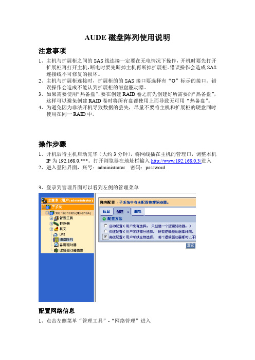
操作步骤1、开机后待主机启动完毕(大约3分钟),将网线插在主机的管理口,调整本机IP为192.168.0.***。
打开浏览器在地址栏输入http://www.192.168.0.3/进入2、进入登陆界面,账号:administrator 密码:password3、登录到管理界面可以看到左侧的管理菜单配置网络信息1、点击左侧菜单“管理工具”-“网络管理”进入2、点击蓝色字体的“端口配置”进入配置界面,这里管理口的网络配置,可根据网络环境进行更改,更改后要用新的IP重新进入Web管理界面3、点击“iSCSI端口”进入,这里列出了主机的4个iSCSI接口的配置信息,点击蓝色字体的“端口配置”,这里可以根据所处网络环境进行iSCSI地址的更改。
创建RAID卷1点击“磁盘阵列”在右边的选项中选择“创建”-“高级配置”,点击“下一步”2创建磁盘阵列别名(可不填),其他默认,在最下面可以看到所有的磁盘信息,选择需要的磁盘点击“>>”移动到右侧,完成后点击“下一步”3创建别名(可不填),选择RAID级别,容量默认为最大,条带默认为512B(这里改为512KB),其他默认。
完成配置后点击“更新”这里选择512KB 4、完成上述操作在最下面的“新建逻辑驱动器”里可以看到配置信息,核对信息无误后点击“下一步”5、再次核对配置信息,确认无误后点击“提交”6、完成RAID卷配置,运行状态“OK”后可以使用。
RAID卡操作手册

图 21 h. 点击 Next 按钮。会进入设置虚拟驱动器(Virtual disk)属性的页面。如前面描 述,可以做详细参数的设置。具体参数和之前设定一样,只是 RAID 级别会变了,这里就不 在说明了。如图 22
图 22
21.若 RAID 发生异常可在 webios 主界面 Logical View 里面显示出相关信息如图 23 所示, RAID5 中有一块硬盘坏掉,找不到磁盘,Driver 显示 SLOT1 插槽物理盘丢失,RAID5 降级。
图3 4.此时,会出现提示窗,如图 4,告知当前的操作会清除掉硬盘上之前的所有 raid 配置信息, 是否要继续,请直接点击 yes 进入下一步:
图4
5.图 5 所示为 RAID 卡的 WebBIOS 管理界面,左侧边栏为功能设定选项,右侧部分会显示 阵列和磁盘的相关状态信息。
图5 6.新建 raid 时,请点击左侧 Configuration Wizard 选项,进行相关结束对虚拟驱动器(Virtual disk)的配置。此时会显示虚拟驱动器虚 拟驱动器(Virtual disk)的信息,如图 17
图 17 18. 如果虚拟驱动器(Virtual disk)的配置信息无误,点击 Accept 按钮保存配置信息。 否则,可以点击 Cancel 按钮来结束该操作并返回到 WebBIOS 的主界面。或者,点击 Back 按钮返回到上一个界面,更改配置信息。 i 如果配置接受之前的配置信息,在弹出确认 2 次保存的提示时,点击 Yes 按钮,保存 配置。
—— Read Policy :指定虚拟驱动器的读取机制,主要包含: 1) Normal : 此选项禁用预读机制。这是默认值。 2) Ahead: 此选项启动预读机制。允许控制器提前顺序读取所需数据并且和其他数据 一起存储在缓存中。这将提高顺序数据的读取速度,但是对读取随即数据的性能没有明显提 升。
EMC-VNX5500磁盘阵列开关机操作指南之欧阳生创编

上海小糸车灯有限公司存储项目VNX5500磁盘阵列开关机操作说明上海软盛信息技术有限公司2012年9月1、设备开机通电1.1开机前的准备1、检查磁盘阵列电源线缆及各部分连接的线缆是否都已经接好。
2、检查供电电源的来源是否是UPS设备输出,其供电电压电流是否稳定3、磁盘阵列在加电前,为确保磁盘柜散热和工作正常,请确认所有磁盘柜的每个槽位都已经插上硬盘和挡风板。
4、开机前需确保至少要有一个正常工作的SP,每个DAE都至少要一块正常工作的LCC。
1.2开机的基本顺序1、打开光纤交换机2、打开磁盘阵列电源3、打开服务器电源1.3磁盘阵列开机的顺序1、打开扩展柜DAE电源2、打开主控制柜DPE、SPS电源3、打开数据移动器(俗称NAS头)DataMover电源备注:对于本次项目,由于配备了EMC机柜及电源,DPE、DAE、DM等设备模块直接打开机柜PDU电源即完成加电。
4、打开ControlStation控制器电源(控制器开机电源见3.3各部分说明)1.4具体操作本次项目VNX5500 for file 和 VNX5500 for unified 可以配备两个刀片(DataMover)以及一个控制站(Control Station)。
操作步骤:1. 验证每个机柜接线板的主开关/断路器是否处于打开状态。
如果要接通包含其他组件的机柜中的VNX5500的电源,请勿关闭机柜的断路器。
确保 SPS开关处于关闭位置。
2. 确保 SP A的电源线插入到SPS中,并且电源线固定扣也扣入到位。
3. 确保 SP B的电源线插入到SPS A之外的另一电路上最近的配电装置(PDU)中,并且电源线固定扣也扣入到位。
在具有两个SPS的系统中,请将 SPB插入到 SPS B中。
4. 验证连接每个 SPS 的电源线是否连接到适当的机柜接线板并且固定扣也扣入到位。
5. 验证全部 DAE的电源线是否已插入到机柜的接线板中。
6. 打开SPS电源开关。
精品16盘位服务器磁盘阵列操作手册V11-金三立视频ST-NT622系列网络枪型说明书优秀

16盘位E-NVS服务器 磁盘阵列操作手册版本号:V1.1声明:由于产品和技术的不断更新、完善,本资料中的内容可能与实际产品不完全相符,本手册内容仅供参考,本手册内容将根据产品功能的增强而更新,如有更新恕不另行通知。
前言非常感谢您使用平台服务器,本平台系统为您提供了一套网络监控应用的整体解决方案。
在计划实施此系统前,请您务必先阅读本手册,以更好理解本系统安装过程和操作过程,以及其他相关信息。
目录一、磁盘管理配置初始化..........................................................................................................- 1 -1.1 WEB管理系统登录......................................................................................................- 1 -1.2系统基本配置................................................................................................................- 2 -1.2.1网络配置.............................................................................................................- 2 -1.2.2 时间设置............................................................................................................- 3 -1.2.3 密码设置............................................................................................................- 3 -1.3 RAID初始化.................................................................................................................- 4 -1.4 创建文件系统.............................................................................................................- 10 -1.4.1 IE管理系统登录..............................................................................................- 10 -1.4.2 RAID状态验证................................................................................................- 10 -1.4.3 创建文件系统..................................................................................................- 12 -1.4.4 创建文件系统验证..........................................................................................- 14 -二、磁盘映射............................................................................................................................- 15 -2.1 shell终端中磁盘映射.................................................................................................- 16 -2.2 WEB网管中磁盘映射................................................................................................- 17 -2.3网管客户端中磁盘映射..............................................................................................- 19 - 附录1 服务器软件安装...........................................................................................................- 20 - 附录2 数据库备份...................................................................................................................- 23 -一、磁盘管理配置初始化1.1 WEB管理系统登录首次登录时在浏览器地址栏中输入服务器默认IP,端口号为88,即http://192.168.0.100:88/ 进入如下所示的登录界面,在登陆框的右侧可以查看主机的设置状态,本机插入了16块磁盘,RAID未建立,其他一切为正常状态。
SOHORAID ST2-B31 產品使用說明说明书
SOHORAIDST2-B31User ManualSOHORAID ST2-B31 User Manual» ST2-B31 User Manual (1)1. Environmental Requirements (1)2. Product Appearance and Packaging Content (1)3. Hardware Requirements and Precautions (2)4. Hardware Installation (3)5. RAID Mode Setting (4)6. Description of HDD Indicators (5)7. Hard Drive Replacement and Data Rebuild Instructions (5)» ST2-B31 產品使用說明 (6)1. 環境需求 (6)2. 產品外觀及包裝內容 (6)3. 硬體需求與注意事項 (7)4. 硬體安裝 (8)5. RAID 模式切換設定 (9)6. 燈號說明 (10)7.更換硬碟與資料重建說明 (10)V1.1SOHORAID ST2-B31 User ManualThank you for choosing the STARDOM product. This manual will familiarize you with the STARDOM ST2-B31 product. We recommend reading through this manual before using the STARDOM ST2-B31 product. The information provided in this manual was checked before publication, but the actual product specifications may have changed before shipping; Latest product specifications and updates can be found at . No separate notifications will be provided by our company. If you would like to receive the latest STARDOM product information, manuals, and firmware, or have any questions regarding STARDOM products, please contact your local supplier or visit www.STARDOM. com.tw for more information.All product-related content in this manual are copyrighted by RAIDON TECHNOLOGY, INC.Operating temperature: 5~35 ℃ (41~95 ℉)Storage temperature : -20~47℃ (-4~116 ℉)Operating voltage: 100~240V ACThe following items should be inside the package upon opening:Please check the product and accessories for any defect or missing parts. If you have any questions, please contact your product supplier.SOHORAID ST2-B31 User Manual Front and rear view1. This system can only transfer data to one computer through one interface at a time.2. After the hard disk is formatted, the actual total capacity of the ST2-B31 detected by the computeroperating system will vary from the sum of all hard disk capacities stated by the manufacturer.3. All existing data will be deleted when this product is set up for the first time. Please ensure that alldata on the hard disk has been backed up before installation to avoid data loss.4. Before a new HDD is installed in the ST2-B31, please make sure that there are no bad tracks ordefects to avoid data loss.5. If the ST2-B31 needs to be shut down or disconnected, please ensure the HDD is safely removedthrough your operating system before turning off the power.6. To prevent data loss, do not remove any of the hard disks while the system is running.7. Once the system has been initialized, do not switch hard disks around during use. Doing so mayprevent the RAID from being recognized by the system.8. Once RAID mode has been set up, the switching of hard drives will lead to the removal of datafrom the hard disks. Please be sure to backup the data on the hard disk before making any switches.9. Please always connect the USB cable to the computer to ensure the energy saving functionoperating normally.10. I f the ST2-B31 needs to be shut down or disconnected, please ensure the HDD is safely removedthrough your operating system before turning off the power.11. Once the computer turn to “Standby” or “Sleep” mode, ST2-B31 will still complete the rebuildingfunction. However, it will not change to “Standby” mode after rebuilding. You need to shut down the ST2-B31 manually or wake up the computer to synchronize “Standby ” or “Sleep” mode together.Front View Rear ViewA. HDD access lightB. HDD enclosure handleC. HDD enclosure keyholeD. Power switchE. Power socketF. USB 3.1 port (GEN2 10Gbps)G. RESET holeH. RAID switchI. FanSOHORAID ST2-B31 User Manual Please follow the steps below to complete the hardware installation process:Use the provided key in the Accessories Kit and inserted it into the Key Access Opening to eject the Removable Drive Tray Latch and extract the Removable Drive Tray.Mount your hard drives onto the removable drive tray and secure it with the screws includedin the accessory kit to avoid any damage to the hard drive due to accidental movements.Step 1Step 212. S T2-B31 uses a 12V/5V AC/DC Adapter. Please do not use other non-certified Power Adapter to avoid damaging to your ST2-B31 unit.13. W e strongly recommend backing up important data stored on the ST2-B31 to another storage device or a remote site. STARDOM will not be held liable for the damage or loss of data you stored on the ST2-B31.Note: Please avoid using hard disk drives from different manufacturers or differentmodels from the same manufacturer as this may impact system performance.Step 3Step 4Step 5Step 6After installing two HDDs into Trays, please insert them into ST2-B31, and then latch the handle.Please set RAID mode at the back-plate of ST2-B31 unit for RAID 1, RAID 0, JBOD, and BIG.Please connect the signal cable first, and then power cord later.After completing hardware installation, turn on the power and follow the instruction of DiskUtility to format the two HDDs, you then could start using your new ST2-B31.SOHORAID ST2-B31 User ManualProvide a big storage capacity and the data transfer efficiency, but no dataporotection feature.Because of this Mirroring feature, your two HDDs/SSDs will keep an identical dataafter your wtiting works. In case one of the two HDDs/SSDs is defect, ST2-B31would still work fine with only one of them. And once inserting a good HDD/SSD asthe defect replacement, it will do the rebuilding work by itself.With JBOD mode, you could actually use the two HDDs/SSDs as the normal twostorages for your large memory capacity requirement!You could enjoy a double memory capacity from this BIG feature.RAID 0:RAID 1:JBOD :BIG :The Standard Procedure to Switch RAID SettingStep-1: Please first connect ST2-B31 to your Mac with Thunderbolt cable..Step-2: Please set RAID Dip Switch to the position you choose.Step-3: Please use the Key to press the hidden RESET key at the back-plate, hold and wait for the end of Blue-Purple LED blinking till a stable Blue light.Step-4: Please turn off your ST2-B31, and re-turn it on again. You now have reset ST2-B31 with a new RAID mode successfully.SOHORAID ST2-B31 User Manual7. Hard Drive Replacement and Data Rebuild Instructions1. During the use of ST2-B31, if you are required to replace a malfunctioning drive, refer to chapter4“Hardware Installation”. Once drive replacement is completed and it is turned on, ST2-B31 will perform data rebuilding procedure automatically.2. If, during the rebuilding process, a drive malfunctions and is unable to continue the rebuilding process,please restart ST2-B31 to check and see that whether the drive is in fact malfunctioning. If it is, please refer to chapter 4 “Hardware Installation” to replace the malfunctioning drive.Note:ST2-B31 allows suspension during data rebuilding process. If you turn off the power during the process, the system will automatically continue to process the remains the next time you turn on the power of the unit. Please do not change the position and sequence of the drives at any time.SOHORAID ST2-B31 User Manual 2.1.感謝您使用STARDOM 的產品。
OWC Mercury Elite Pro 硬盘阵列说明书
M E R C U R Y E L I T E P R O Assembly Manual & User GuideINTRODUCTION (1)1.1 MINIMUM SYSTEM REQUIREMENTS1.1.1 Apple Mac Requirements 1.1.2 PC Requirements 1.1.3 Supported Hard Drives1.2 PACKAGE CONTENTS 1.3 ABOUT THIS MANUAL 1.4 REAR VIEW1.4.1 Connection1.5 LED INDICATORDEVICE SETUP (3)2.1 QUICK START 2.2 ASSEMBLYSUPPORT RESOURCES (7)3.1 FORMATTING3.2 UNMOUNTING DRIVES 3.3 TROUBLESHOOTING 3.4 ABOUT DATA BACKUP 3.5 ONLINE RESOURCES3.6 CONTACTING TECHNICAL SUPPORTTABLE OF CONTENTS1.1.3 Supported Hard Drives Any 3.5” SATA hard drive1.3 ABOUT THIS MANUALThe images and descriptions may vary slightly between this manual and the unit shipped. Functions and features may change depending on the firmware version. Please visit the product web page for the most recent product specifications.1.1.1 Apple Mac Requirements eSATA: OS X 10.3 or later FireWire: OS X 10.3 or laterUSB 3.1 Gen 1 (backwards compatible to USB 2.0): OS X 10.6 or later 1.1.2 PC RequirementseSATA: Windows® XP or later FireWire: Windows XP or laterUSB 3.1 Gen 1 (backwards compatible to USB 2.0): Windows XP or later1.1 MINIMUM SYSTEM REQUIREMENTS1.2 PACKAGE CONTENTSFireWire 800(1394b) cableeSATA cableUSB 3.1 Gen 1 (A to Standard-B) cable Mercury Elite Pro (with vertical stand)Power supply andpower cableINTRODUCTION1.4 REAR VIEW1.4.1 ConnectionPlug the power supply into a power outlet and then into the Mercury Elite Pro. Next, connect the USB 3.1 Gen 1, FireWire 800, or eSATA cable into the drive and the corresponding port on your computer. USAGE NOTES• If you connect the Mercury Elite Pro to its power source and turn the unit on without connecting it to a computer, the drive will temporarily spin up and then spin back down when a data connection is not detected. • Only one interface (FireWire 800, USB 3.1 Gen 1, or eSATA) at a time can be used.• For the safe removal of your drive and to ensure that no data is lost, always unmount the drive from your operating system before powering off the Mercury Elite Pro. •In order for the computer to access volumes larger than 2TB, the operating system needs to support large volumes (e.g., Windows Vista or OS X 10.4 and above).1.5 LED INDICATORThe Mercury Elite Pro has a blue LED at the front of the enclosure. The LED emits a solid light when the unit is powered on, and a flashing light during hard drive activity.2.1 QUICK STARTTo format this drive for Mac OS X (OS 10.4 and later) or Windows (XP and later), follow the steps below. If you installed your own drive, please use the formatting method you are most familiar with or check Section 3.1 for a link to OWC’s online formatting tips.1. Plug in the power supply then connect the Mercury Elite Pro to your computer using the proper cable. If you prefer to use a different formatting utility, do so at this time and skip the rest of these instructions.2. Your drive will show up as “OWC SETUP”. Open your drive to view its contents.3. D ouble-click the OWC Drive Guide application.4. F ollow the simple on-screen instructions to complete the formatting process.5. O nce the formatting is finished the drive is ready to use.2.2 ASSEMBLYNOTICE: The following assembly instructions are written for users who purchased the Mercury Elite Pro as an empty enclosure. The instructions show how to open the Mercury Elite Pro in order to install a drive. If you purchased the Mercury Elite Pro with a drive already installed, opening the Mercury Elite Pro before the expiration of the original warranty will VOID the warranty. If you wish to remove or replace a drive after the expiration of the original warranty, you may do so at that time.1. Remove the Mercury Elite Pro from the retail box and the protective plastic bag.Set the Mercury Elite Pro on its side and look at the bottom of the enclosure. Usea Phillips screwdriver to remove the two screws, circled below in red.DEVICE SETUP2. Once the two screws are removed, slide the inner chassis out the front of the outer case, as shown below. Start by pushing on the back of the inner chassis, then when you are able to grip the front grill of the inner chassis, pull it out the rest of the way.3. When removed from the outer case, the inner chassis will appear as shown below. Remove the packet of screws and use them as directed later in the assembly instructions.4. To install the hard drive, slide it into the black SATA connector inside the Mercury Elite Pro. You may need to move the blue and black LED cables to the side in order to make room for the hard drive. Make sure the drive is firmly seated before proceeding.5. Using the four screws from the packet you removed from the inner chassis, fasten the hard drive to the inner chassis. There are two screw holes on each side of the inner chassis, circled below in red.6. Slide the inner chassis back into the outer case, as shown below.7. Once the front grill of the inner chassis sits flush with the edge of the outer case, turn the Mercury Elite Pro on its side. Use the two smaller screws you removed in Step 1, and refasten the outer case to the inner chassis.3.1 FORMATTINGFor formatting information, including instructions on how to format your OWC M ercury Elite Pro for Mac or Windows, go to: /format3.2 UNMOUNTING DRIVESTo properly unmount any connected drive from your computer, try the options below.OS X:There are several methods to unmount disks with OS X systems. You can drag the icon for the disk you wish to unmount to the trash can, or right-click the disk icon on the desktop, then click “Eject”. You can also eject the disk in the sidebar of a Finder window, or by selecting the drive icon on the Desktop then pressing Command-E.Windows:1. Go to the System Tray (located in the lower right corner of your screen). Click on the “Eject” icon (a small green arrow over a hardware image).2. A message will appear, detailing the devices that the “Eject” icon controls, i.e., “Safely remove...” Click on this prompt.3. Y ou will then see a message that says, “Safe to Remove Hardware.” It is now safe to disconnect the Mercury Elite Pro from the computer.3.3 TROUBLESHOOTINGBegin your troubleshooting by verifying that the power cable is connected to the Mercury Elite Pro and to a power source. If the power cable is connected to a power strip, make sure that the power switch on the strip is turned on.Then, simply verify that both ends of your cables are properly plugged into the computer and the Mercury Elite Pro. If the Mercury Elite Pro is still not working properly, try connecting to another interface such as the USB connection and see if the device works properly. You can also connect the Mercury Elite Pro to a different computer. If problems persist, seeSection 3.6to contact OWC technical support.SUPPORT RESOURCES3.4 ABOUT DATA BACKUPTo ensure that your files are protected and to prevent data loss, we strongly suggest that you keep two copies of your data: one copy on your OWC Mercury Elite Pro and a second copy on your internal drive or another storage medium, such as an optical backup, or on a second external storage unit. Any data loss or corruption while using the Mercury Elite Pro is the sole responsibility of the user, and under no circumstances may OWC, its parents, partners, and affiliates be held liable for loss of the use of data including compensation of any kind or recovery of the data.3.5 ONLINE RESOURCESData Migration:For a step-by-step walkthrough of our recommended method for migrating your data from an old drive to a new one, go to:/support/data-transferFAQs:Access our online collection of frequently asked questions for this and other products at: /support/faq3.6 CONTACTING TECHNICAL SUPPORT8AM - 8PM (CT) Monday - Friday9AM - 4PM (CT) Saturday(866) 692-7100 (North America)+1 (815) 338-4751 (International)Live chat is available during normal business hours at:/support/Email support is available at:/support/Changes:The material in this document is for information purposes only and subject to change without notice. While reasonable efforts have been made in the preparation of this document to assure its accuracy, OWC and its officers and employees assume no liability resulting from errors or omissions in this document, or from the use of the information contained herein. OWC reserves the right to make changes or revisions in the product design or the product manual without reservation and without obligation to notify any person of such revisions and changes.FCC Statement:Warning! Modifications not authorized by the manufacturer may void the user’s authority to operate this device.NOTE: This equipment has been tested and found to comply with the limits for a Class A digital device, pursuant to Part 15 of the FCC Rules. These limits are designed to provide reasonable protection against harmful interference when the equipment is operated in a commercial environment. This equipment generates, uses, and can radiate radio frequency energy and, if not installed and used in accordance with the instruction manual, may cause harmful interference with radio communications. Operation of this equipment in a residential area is likely to cause harmful interference, in which case the user will be required to correct the interference at his own expense.NOTE: This equipment has been tested and found to comply with the limits for a Class B digital device, pursuant to Part 15 of the FCC Rules. These limits are designed to provide reasonable protection against harmful interference in a residential installation. This equipment generates, uses and can radiate radio frequency energy and, if not installed and used in accordance with the instructions, may cause harmful interference to radio communications. However, there is no guarantee that interference will not occur in a particular installation. If this equipment does cause harmful interference with radio or television reception, which can be determined by turning the equipment off and on, the user is encouraged to try to correct the interference by one or more of the following measures:• Reorient or relocate the receiving antenna.• Increase the separation between the equipment and receiver.• Connect the equipment to an outlet on a circuit different from that to which the receiver is connected.Health And Safety Precautions:• Use proper anti-static precautions while performing the installation of your hard drives into this drive enclosure. Failure to do so can cause damage to your drive mechanisms and/or the hard drive enclosure.• Read this user guide carefully and follow the correct procedures when setting up the device.• Do not attempt to disassemble or modify the device. To avoid any risk of electrical shock, fire, short-circuiting or dangerous emissions, never insert any metallic object into the device. If it appears to be malfunctioning, contact OWC technical support.• Never expose your device to rain, or use it near water or in damp or wet conditions. Never place objects containing liquids on the drive, as they may spill into its openings. Doing so increases the risk of electrical shock, short-circuiting, fire or personal injury.Copyright 2016 OWC. All Rights Reserved. OWC’s Limited Warranty is not transferable and subject to limitations.General Use Precautions:• To avoid damage, do not expose the device to temperatures outside the range of 5° C to 40° C (41° F to 104° F).• Always unplug the device from the electrical outlet if there is a risk of lightning or if it will be unused for an extended period of time. Otherwise, there is an increased risk of electrical shock, short-circuiting or fire.• Do not use the device near other electrical appliances such as televisions, radios or speakers. Doing so may cause interference which will adversely affect the operation of the other products.• Do not place the device near sources of magnetic interference, such as computer displays, televisions or speakers. Magnetic interference can affect the operation and stability of hard drives.• Do not place heavy objects on top of the device.• Protect your device from excessive exposure to dust during use or storage. Dust can build up inside the device, increasing the risk of damage or malfunction.• Do not block any ventilation openings on the device. These help to keep the device cool during operation. Blocking the ventilation openings may cause damage to the device and cause an increased risk of short-circuiting or fire.•For up-to-date product and warranty information, please visit the product web page.Copyrights and Trademarks:No part of this publication may be reproduced, stored in a retrieval system, or transmitted in any form or by any means, electronic, mechanical, photocopying, recording or otherwise, without the prior written consent of OWC.© 2016 OWC. All rights reserved.OWC is a trademark of New Concepts Development Corporation, registered in the U.S. Patent and Trademark Office and/or in Canada. The OWC logo is a trademark of New Concepts Development Corporation. Apple, FireWire, Mac, and OS X are trademarks of Apple Inc., registered in the U.S. and other countries. Windows is a registered trademark of M icrosoft Corporation in the U.S. and other countries. Other marks may be the trademark or registered trademark property of their owners.OWCMANMEPU3FWESR4 04/12/16 DM。
UBS 系列盘阵 Raid 卡 说明书
UBS静音高速盘阵和Raid卡-----2K/HD/SD/视频和动画制作的必需品:您在制作影像节目是,无论是作2K高清视频、二维三维动画、视频合成还是非编,都会碰到最主要问题就是A V硬盘阵列速度不够,或者是Raid控制器速度不稳不够快。
如果您有UBS系列静音高速盘阵,所有问题一下就解决了UBS系列盘阵说明:UBS系列影视专用阵列卡:•支持多达4-24个SATAII硬盘,通过PCI-Express 接口,适应大量的数据处理能力,现在最大SATA2硬盘为1000G也就是说UBS外置盘阵可以最大支持24X1000G=24T,由于SATA2的硬盘价格比较低廉,所以UBS盘阵也是最具有性价比的盘阵.•阵列卡内置intel 341和intel333 X, intel332 XScale处理器核心的高速存储芯片,是intel 最新的基于硬件的RAID5/6技术,每个卡自带内存,有的型号也可以升级到2G,•支持直写和回写缓存模式,支持RAID0,1,3,5,6和JBOD ,•支持在线RAID级别迁移.在线容量扩充,硬盘插入或移动时自动侦测,如发生故障后换掉硬盘,数据资料自动恢复和资料重建,通过硬盘活动/失败连接线,LCD连接线和警报峰鸣器来表明当前状态。
•简易的RAID管理UBS阵列卡 bios内含终端模拟器,通过bios的启动界面,通过这种管理程序可以简化RAID控制卡的设置和管理,还建立在HTTP浏览器的程序通过驱动rcHttp Proxy进入。
在Windows ,Linux,MACOSX(10.4.X)环境下,通过Browser base的管理程序与内建的HTTP 完成本地或远程对RAID set, volume set, and monitor RAID的建立和修改状态。
•提供专用UBS MiniSAS 线缆•支持windows 2000/xp /server2003,MAC OSX (10.4.X),UnixWare 7.1.X,Redhat Linux,SuSE Linux,FreeBSD,Solaris10x86•UBS外置整列箱:外观时尚漂亮,结构扎实小巧,超低静音UBS盘阵特性 应用好处板载最新高科技核心intel存储CPU的硬件阵列卡 UBS的所有阵列卡都内置intel 341和intel333,332 XScale处理器,是 intel的最新一代高速存储芯片.此CPU集成1M的二级缓存,最大特点是高速和稳定的运算能力,在盘阵的作数据重建的时侯,UBS的盘阵是可以在继续正常工作的,不占用主机CPU的资源和影响你的工作时间.带ECC校验内存的硬件阵列卡 UBS的所有阵列卡都板载533MHzDDR2ECC 64-bit 256M内存,最大能到2048内存,能把你的数据更高效和稳定的应用和调动起来.最新的intel块保护技术 UBS的所有阵列卡都支持最新的intel块保护技术,提供了端到端数据保护实时硬盘状态监控技术 UBS的所有盘阵都支持I2C通信协议,提供完整的状态及硬盘环境系数监控功能,当硬盘不能正常工作时,UBS的阵列卡会自己发出蜂鸣声,同时阵列箱上的黄灯要开始连续闪烁.令人吃惊的读写速度 当用UBSHD3418P8 个盘作 RAID 5工作的时侯,连续读写都能跑到500M/S左右高性价比的最佳方案 SATAII的硬盘现在有的是750G的比较稳定,当 8个750G作raid5 等于5T,同样容量的光纤盘阵的方案要比UBS系列盘阵贵上一倍还多完美的多平台支持 UBS系列盘阵是一个多平台的支持盘阵,支持MAC OS,和Winxp32bit ,Winxp64bit.也支持UnixWare 7.1.X,Redhat Linux,SuSE Linux,FreeBSD,Solaris10x86,可以在多种平台的应用上助你一臂之力四个SATAII硬盘就可以支持高清编辑当你的预算有限制的时侯,你可以选择UBSHD3414P盘阵,配上4个SATA的硬盘,这样可以在RAID5的情况跑到200M/S 左右,也可以支持你的高清编辑.型号和配置:UBS 备有数种不同的内置外置或481216口Raid 卡,满足不同的工作站要求,详情请咨询***********或***********独有的RAID6双重保护功能RAID6设计可以支持2 个硬盘在同一时间段故障,而不影响数据的存取,双重的保护,可以确保数据完整无失。
16盘位服务器磁盘阵列操作手册V1.1-金三立视频ST-NT622系列网络枪型说明书
16盘位E-NVS服务器 磁盘阵列操作手册版本号:V1.1声明:由于产品和技术的不断更新、完善,本资料中的内容可能与实际产品不完全相符,本手册内容仅供参考,本手册内容将根据产品功能的增强而更新,如有更新恕不另行通知。
前言非常感谢您使用平台服务器,本平台系统为您提供了一套网络监控应用的整体解决方案。
在计划实施此系统前,请您务必先阅读本手册,以更好理解本系统安装过程和操作过程,以及其他相关信息。
目录一、磁盘管理配置初始化..........................................................................................................- 1 -1.1 WEB管理系统登录......................................................................................................- 1 -1.2系统基本配置................................................................................................................- 2 -1.2.1网络配置.............................................................................................................- 2 -1.2.2 时间设置............................................................................................................- 3 -1.2.3 密码设置............................................................................................................- 3 -1.3 RAID初始化.................................................................................................................- 4 -1.4 创建文件系统.............................................................................................................- 10 -1.4.1 IE管理系统登录..............................................................................................- 10 -1.4.2 RAID状态验证................................................................................................- 10 -1.4.3 创建文件系统..................................................................................................- 12 -1.4.4 创建文件系统验证..........................................................................................- 14 -二、磁盘映射............................................................................................................................- 15 -2.1 shell终端中磁盘映射.................................................................................................- 16 -2.2 WEB网管中磁盘映射................................................................................................- 17 -2.3网管客户端中磁盘映射..............................................................................................- 19 - 附录1 服务器软件安装...........................................................................................................- 20 - 附录2 数据库备份...................................................................................................................- 23 -一、磁盘管理配置初始化1.1 WEB管理系统登录首次登录时在浏览器地址栏中输入服务器默认IP,端口号为88,即http://192.168.0.100:88/ 进入如下所示的登录界面,在登陆框的右侧可以查看主机的设置状态,本机插入了16块磁盘,RAID未建立,其他一切为正常状态。
磁盘阵列使用说明
磁盘阵列正面图:磁盘阵列背面图:1,打开背面风扇的电源(2个),磁盘阵列启动,背面上面的的一个网口是控制口,设定和修改参数必须通过这个口访问,下面并排4个口是通道口,用来数据的交换和储存。
2,在前面板有个液晶微型控制键盘,用来配置磁盘阵列,按键操作说明:ENT长按——进入主菜单方向键——翻页ENT短按——选择对应的菜单3,查看后面控制口(lan)和通道口(ch0~3)的IP地址,以此进入下列菜单view and edit configuration parameters->conmunication parameters->internet protocol (tcp/ip)->然后选择需要查看的网口,我们现在查看控制口lan的IP,选择lan0->view and set ip address 查看当前的lan口IP或者更改IP,详细配置方法可看附录1《利用液晶面板设置IP地址.pdf》为方便叙述,现在假设lan口IP为192。
168.0.2,ch0口IP为192.168.0.3,ch1为192.168.0.4通过IE配置磁盘阵列4,通过IE输入LAN口地址,//192.168.0.2选择configuration,密码为空,进入配置界面。
5,选择logic Drive->create logical Drive(创建RAID),绿色的是可以使用的硬盘。
选择要创建RAID的硬盘,这里选取5块硬盘来创建RAID5+space,在RAID Level里选择RAID5+space Drive,其他默认,点击APPL Y确认创建6,给创建的RAID分区,,点击图画的raid阵列,然后选择PARTITION进入分区列表7,在下图位置点加号新建分区,减号删除分区8,创建好分区,点击左边标题栏;host lan->Creat lan创建映射,点击下面的位置,可以看到分区列表;9,选中1个分区,根据所要用的CH通道口,将分区映射到通道,这里我们把分区全部映射到ch0,选中p0分区,将channel physical no选择0,点击apply确认。
- 1、下载文档前请自行甄别文档内容的完整性,平台不提供额外的编辑、内容补充、找答案等附加服务。
- 2、"仅部分预览"的文档,不可在线预览部分如存在完整性等问题,可反馈申请退款(可完整预览的文档不适用该条件!)。
- 3、如文档侵犯您的权益,请联系客服反馈,我们会尽快为您处理(人工客服工作时间:9:00-18:30)。
奥睿科磁盘阵列说明书
随着高品质资源的普及,硬盘的容量也水涨船高,一部高品质的蓝光电影就有四五十G,加上各种资源,电脑越来越吃不消,前几年网盘非常方便,但是网盘的安全性以及私密性相比于本地存储还是差距明显,一些机密数据更加需要安全,加上严密的监管也就使得本地存储更有优势。
建立一个数据仓库无疑是解决的好办法,固态SSD价格太贵,移动硬盘性价比不高,而且无法组RAID,机械硬盘就成为了一个廉价的大仓库,存储硬盘柜还可以多个机械硬盘组建RAID,本文的ORICO WS200RC3 3.5英寸蜂巢存储硬盘柜有多种盘位可以选择,采用全铝材质机身,最大单盘支持10TB。
奥睿科WS系列蜂巢存储硬盘柜有3个型号,分别是双盘、四盘和五盘,本次体验的是双盘硬盘柜。
这款WS200RC3硬盘柜的白色包装采用了手提式,主要是重量便于携带,正面印有产品的效果图,比较引人注目的的是右上角印有PICC承保字样,上了保险的硬盘盒安全性还是很自信的。
性能特点有Type-C、USB3.1、Gen2接口、UASP加速协议、RAID模式,其中RAID0模式下最高达10Gbps。
WS200RC3硬盘柜最高支持10TBx2的极限扩容。
WS200RC3的包装盒侧面是相关规格参数以及厂家信息,如型号尺寸以及支持的系统,其中包括Windows/Mac/Linux系统,以及厂商的联系方式等。
打开WS200RC3的包装,硬盘柜和配件盒是独立的,硬盘柜有泡沫海绵进行了保护,全部配件被放置在一个白色小盒子里,当然还有一本中英文说明书。
配件包含专业的电源适配器以及电源线,有点类似笔记本电脑的电源配置,
Type-C to Type-C数据线一条,USB-A to Type-C数据线一条,专用内角螺丝刀一个,螺丝若干,以及使用说明书和保修卡。
12V 4A大功率专用电源适配器,配套设施的配置也很强大,由于采用了定制化的电源所以无法替代,外出携带需要占据一定的空间。
中英文说明书和致谢卡,说明书是WS系列的,当然包含了双盘、四盘和五盘硬盘柜的3个型号功能介绍,四盘和五盘硬盘柜很多功能双盘是没有的。