微机控制高频开关电源柜使用说明书-艾默生
高频电源设备操作说明

高频电源设备操作说明操作步骤一:开启电源在操作高频电源设备之前,请确保设备已经连接到电源插座,并确认电源插头已牢固插入。
接下来,按下电源开关,启动设备。
在设备启动过程中,注意观察指示灯,确保电源已经成功开启。
操作步骤二:选择工作模式高频电源设备通常具有多种工作模式,根据实际需要选择相应的模式进行操作。
常见的工作模式可能包括恒压模式、恒流模式等。
通过操作面板上的选择按钮或旋钮,将工作模式切换至所需的模式。
操作步骤三:设置参数根据实际的电源需求,设置电源工作时的参数。
这些参数可能包括输出电流、输出电压等。
通过操作面板上的参数调节按钮或旋钮,逐步调整设备的参数至所需的数值。
在调节参数过程中,要注意保持稳定且适当的调整速度,避免过快过慢的调节。
操作步骤四:连接负载在设备参数设置完成后,将负载连接至设备输出端口。
根据不同高频电源设备的接口要求,选择适当的连接方式,确保连接牢固且正确。
在连接负载之前,要确保设备已经正确接地,并按照设备说明书的要求进行操作。
操作步骤五:启动设备连接负载后,对设备进行最终检查,确保所有设置无误、负载连接正确。
然后按下设备启动按钮,启动设备供电。
在设备启动后,可以通过观察指示灯的状态或操作面板上的显示屏,确认设备是否正常工作。
操作步骤六:监测设备运行在设备正常运行后,要定期监测设备的运行状态,包括输出电流、输出电压等参数是否在设定范围内。
如果发现异常情况,应及时停止设备运行,并按照设备说明书中的故障排除方法进行处理。
操作步骤七:关闭设备当设备使用完毕或需要停止运行时,首先断开负载连接,然后按下设备停止按钮,使设备停止供电。
在设备完全停止运行后,拔下电源插头,断开设备与电源的连接。
注意事项:1. 在操作高频电源设备时,应仔细阅读设备的操作说明书,并按照要求进行操作。
2. 在操作过程中,注意安全。
避免接触设备内部的高压部件,避免设备受到外部的震动或撞击。
3. 如需更改参数、工作模式等设置,应在设备完全停止运行后进行调整。
艾默生高频开关电源柜日常检修单项作业指导书(时间检查校对)

通信电源日常检修单项作业指导书(艾默生高频开关电源柜)(时间检查校对)1.安全控制措施安全控制措施作业人员严禁佩戴戒指、手表等金属饰品。
2.作业前准备维修周期季作业人员2名作业时间3分钟维修条件维修计划(天窗点内)作业工具万用表等配套工具检修依据《铁路通信维护规则》TG/TX106-20143.作业过程一、进入机械室后首先向动力环境网管汇报,汇报内容包括单位部门、姓名、作业内容,并在《入室登记本》上登记。
二、时间检查校对进入高频开关电源控制器监控菜单,查询当前系统时间(含日期)是否正确,要求与车站运转室MIS时间同步。
如系统时间与车站运转室当前MIS时间不同步,需进行核对调整。
在高频开关电源控制器监控菜单界面中操作翻页键移动手指光标到“系统参数”菜单项,按确认键,弹出输入操作密码界面;按左右键输入正确操作密码进入时间设置调整界面;按车站运转室当前MIS 时间进行参数更改设置,确认后按返回键退回运行信息界面。
M500D监控模块操作按键说明表三、全部作业完成后,联系汇报网管确认设备工作正常,无告警信息。
检查工具有无遗漏,并在《入室登记本》登记离开时间,查看机械室内无异常现象后离开。
4.关键提示:1.用密码登录系统参数设置项时,对其它参数设置菜单不得擅自改变修改数据。
2、进入系统参数修改,需一人操作,一人复核。
5.发生问题的处置:1.作业中发现紧急告警,应立即向网管报告,听从网管指挥,启动相应应急预案。
2.作业中发现任何异常,应立即向调度汇报。
3.检修完毕应进行复核,确认设备运行状况,填写通信设备检修记录本。
GZDW说明书(艾默生PSM-E01)
GZDW智能高频开关电源直流电源柜使用说明书SLY苏州市龙源电力工程有限公司i前言由于直流电源设备存在能危及人身安全的高电压,危及供电电网安全的操作要求,请在安装、使用设备前查阅本手册的相关内容。
声明:由于产品和技术的不断更新、完善,本资料中的内容可能与实际产品不完全相符,敬请谅解。
如需查询产品的更新情况,请联系我公司。
ii苏州市龙源电力工程有限公司3电力操作电源系统概述一 、系统原理:电力操作电源主要应用在发电厂、水电站、各类变电站中,为断路器分合闸及二次回路中的仪器、仪表、继电保护和故障照明提供直流电源。
电力操作电源系统主要由交流配电单元、充电模块、监控模块、降压单元、电池巡检单元、直流馈电单元(包括合闸分路、控制分路)、绝缘监测等几大部分组成。
由于不同的接线方式在输出馈电部分有所不同,但基本原理是一致的。
框图如图1所示:图1 电力操作电源系统原理框图系统工作原理如下:系统交流输入正常时,两路交流输入经交流切换控制电路选择其中一路输入,并通过交流配电单元给各个充电模块供电。
充电模块将输入三相交流电转换为110V 或220V 的直流,经隔离二极管隔离后输出,一方面给电池充电,另一方面给负载提供正常工作电流。
监控部分采用集中方式对系统进行监测和控制,充电模块运行参数由模块监控电路采集处理,然后通过串行通讯方式把处理后的信息传给监控模块,由监控模块统一处理后,显示在液晶屏上。
同时可通过人机交互操作方式对系统进行设置和控制,若有需要还可接入远程监控。
监控模块还能对每个充电模块进行均浮充控制,限流控制等,以保证电池的正常充电,延长电池寿命。
苏州市龙源电力工程有限公司4二、显示启动屏在确认接线无误后,合上PSM-E01监控模块外部配电开关给监控模块上电,先出现如下启动屏。
启动屏显示主信息屏启动完后,监控模块自动出现如下的主信息屏。
第一行的日期和时间交替显示,第二行显示的是合闸母线电压与负载电流,第三行显示的是系统状态(正常或告警),第四行显示的是系统进行蓄电池管理运行状态(自动或手动),以及电池状态(浮充、均充或放电)。
微机控制高频开关电源柜使用说明书-艾默生
操作使用说明无锡市凯杰电器有限公司编制第一部分、系统一、系统概述GZD(W)微机型高频直流电源,是专为电力系统设计的一种较为理想的直流电源系统。
其主要功用是为电力系统变电所的高低压开关设备提供必要的操作电源,为继电保护或微机保护装置提供工作电源以及作为事故照明、应急电源和他直流用电设备电源。
由于本直流电源系统采用了新型高频开关电源模块和微机监控单元,电源的质量和系统的工作可靠性有显著提高,并可实现蓄电池的充、放电智的智能化管理和在线检测、直流电源系统数据的适时监控、报警及远程控制,因此,它广泛的用于现代的无人职守变电所、发电厂,也同样适用于通信部门、计算机房、医院、宾馆以及高层建筑的供电领域,应用十分广泛。
二、系统构成GZD(W)微机型直流电源系统主要由高频开关电源模块、监控微机单元、蓄电池组及馈出线路等部分组成。
1、高频开关电源模块本公司高频开关电源模块统一采用艾默生高频开关电源模块,为本直流电源系统核心部件。
其功用如下:a、为蓄电池组提供均充、浮充电电流;b、为电站所有直流用电设备提供正常负荷电流。
2、蓄电池组蓄电池组在本系统中作为电能储备装置,在交流电源中断或高频充电模块不能正常工作时向负载提供电能。
情况如下:a、正常情况下蓄电池组处于受电工作状态,即接受高频开关电源模块提供的浮充或均充电电流,确保满容量;b、在事故或大功率冲击性用电负载工作时为用电设备提供电能。
3、微机监控单元a、监控蓄电池均、浮充电的智能化管理;b、监视直流电源系统并在系统出现异常时发出告警信息。
监视的模拟量如:合闸母线电压、蓄电池组电压/电流/、控制母线电压/电流等监视的开关量如:直流开关状态、熔断器状态、绝缘状态、模块状态等;c、和上位机通讯联系,实现遥信、遥测上传。
4、馈出线路将直流电源分配和输送到各用电负荷。
包括直流断路器和出线。
三、功能特点1、系统采用了高频开关电源模块并采用N+1模式运行,电压质量和系统可靠性大大提高2、系统采用了微机系统监控,实现了系统和蓄电池的智能化管理和远程通讯,可实现电站无人职守。
艾默生开关电源用户手册31010887

PS48400-2C/50智能高频开关电源系统用户手册E1-20020314-C-1.0艾默生网络能源有限公司PS48400-2C/50智能高频开关电源系统用户手册资料版本E1-20020314-C-1.0BOM编码31010887艾默生网络能源有限公司为客户提供全方位的技术支持,客户可与就近的艾默生网络能源有限公司办事处或客户服务中心联系,也可直接与公司总部联系。
艾默生网络能源有限公司地址:深圳市龙岗区坂雪岗工业区华为基地电气厂房一楼、三楼邮编:518129公司网址:或E-mail:****************版权声明艾默生网络能源有限公司版权所有,保留一切权利。
在没有得到本公司书面许可时,任何单位和个人不得擅自摘抄、复制本书(软件等)的一部分或全部,不得以任何形式(包括资料和出版物)进行传播。
版权所有,侵权必究。
内容如有改动,恕不另行通知。
Copyright by Emerson Network Power Co.,Ltd.All rights reserved.The information in this document is subject to change without notice. No part of this document may in any form or by any means (electronic, mechanical, micro-copying, photocopying, recording or otherwise) be reproduced, stored in a retrieval system or transmitted without prior written permission from Emerson Network Power Co.,Ltd.内容介绍本手册介绍了PS48400-2C/50智能高频开关电源系统的组成、安装、调测、日常使用维护及故障的应急处理。
艾默生精密空调操保手册
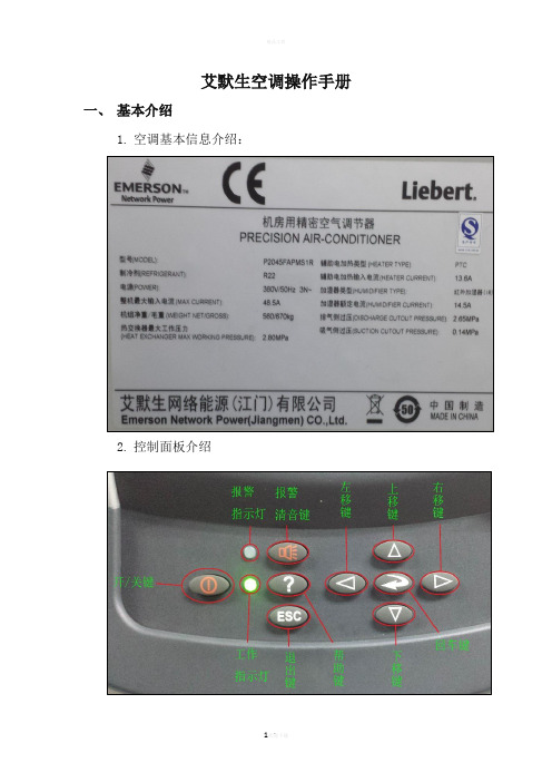
艾默生空调操作手册一、基本介绍1.空调基本信息介绍:2.控制面板介绍3.控制面板的操作:①设定点:按回车键进入菜单,再按回车键,通过方向键输入密码。
按下移键选中设定点图标(如下图所示),按回车键进入菜单。
②进入菜单后再按回车,选着索要更改的项目,按回车键,进入到如下图所示的画面,按上移键或下移键改变要改变的数值,然后按回车键确定。
修改完毕后按退出键返回主界面。
③设定点可设置的数值有:⑴温度设定⑵湿度设定⑶湿度控制⑷送风功能⑸送风温度⑹备份温限注:其他菜单设置的操作步骤与设定点设置方法相同。
二、设备保养1、更换过滤网①打开机柜门,将机柜顶部两个旧的过滤网取下来。
②将新的过滤网平稳的放在机柜的顶部(注意方向)。
2、更换风机皮带①空调关机,在确定停止后,打开机柜门取下挡板。
②抬起电机去下皮带,检查皮是否有断裂、老化现象。
③安装皮带(注意:防止皮带与皮带轮之间夹手)。
④安装挡板。
3、清洗水槽①空调关机拆下两块挡板,拆下立柱上的螺丝。
②将水位传感器拆下来。
③将排水管,传感器拆下来。
④拆掉水槽两端螺丝,平行抽出水槽,清洗。
⑤清洗完毕按顺序安装。
欢迎您的下载,资料仅供参考!致力为企业和个人提供合同协议,策划案计划书,学习资料等等打造全网一站式需求⑥。
艾默生电容补偿器控制器用户手册说明书
v Read the manual carefully before the device isinstalled.v Only qualified staff is allowed to perform theinstallation.v Connect the relay as per the wiring diagram inthe manual.v Before connecting the relay check the supplyvoltage.v Please check whether the CT is connected atthe Main Incomer.v Connect the CT when the relay is in OFFcondition. Use suitable size cable for the CT.v Do not disturb the connection when the relay isON.v Please ensure the discharge time interval ofcapacitor.v Disconnect the device if it does not work duringcommissioning.v Do not install the device if it is in damagedcondition.OPERATION & INSTRUCTIONMANUALØSuitable for Thyristor switched Capacitor panel.ØVarious possibilities for bank selection. Including user defined bank values in KVAR. ØInput sensing line-to-line voltage.ØSelectable current input range. 1Amp and 5Amp. (CT input)ØProtection against Over/Under voltage, Over/Under ØCompensation on fundamental waveform, KVAR calculation and also the effects of supply frequency and voltage.ØØStandard 144 X 144 mm panel flush mountingarrangement. Max depth 60mm. Recommended cutout for panel front door is 138x138 mm.Features:ØMeasurement Voltage (L-L): 415 Volt + 10 %.ØInput Measurement Current: 1A / 5 A.ØContact rating for output suitable for 1Amp, 440V ØMeasurement accuracy: Class-1ØOperating temperature: 0 to 55°C. ØStorage temperature: -10 to +75°C ØOutput commands models for 8,12 and 16 output.Specifications:POWER FACTOR CONTROLLERThe Display is LCD and the factory set (Default) condition shows the PF, which is power factor, sensed from the load sensing CT i.e. the Transformer/supply grid. The screen also shows “ IND” for Inductive Power Factor & “ CAP” forCapacitive Power Factor. The last digit on the upper line of display shows the operation mode i.e. 'A 'for auto mode and 'M' for Manual mode. The bottom line of the LCD display shows capacitor bank status.Display in other Parameters:To observing other system related parameters Scroll up/down keys. Following is the sequence of the parameters displayed on LCD screen.Display Overall Values : Displays the Overall values(average) like voltage, current, Active Power, Reactive Power, Apparent power, Frequency.Display Power : Displays the power related Parameters like P .F., kW, kVA, and kVAr.Display Step kVAr : Displays the values of kVAr output i.e. measured for every step.Display Auxiliary Functions .Display:Fault Finding Guidelines:Fault TypeProbable ReasonAction to TakeUnit Does not turn ON. LCD is blank with no Backlit.q Input supply not coming.q Input side fuses blownü Check the input supply to restore ü Check fuses in the unit for OK.Unit not turning ON any capacitor banks, immediately after Power on.This is perfectly OK if unit is powered up, there is a delay of correction timethat is provided in the unit only after which units can turn on outputs.As this is normal action, need not take any action. Unit will start performing normally after the stipulated time delay.With whatever capacitor banks ON,SPF does not indicate the PF asimproved.Check connection as per controlwiring diagram. Check that Load CT put is in correct phase Correct the wiring as per the scheme requirements and the CT positioning.Relay shows Capacitive PF whilethere is No Capacitive Load Phase Sequence of CTCheck the KW in the Relay if it is negative Interchange the CT polarity.Main Energy Meter PF reading &Relay PF reading is not matched q CT position & ratingq Excessive Distance betweenRelay & Energy Meterü Check the CT position & correct it as per given in Scheme 1 or 2.ü CT wiring should be up to 10mtr.Thyristor controlled by this unit is/are not turning ON/OFF even if front LCD indication shows correct.q Wiring to the command wiring isopen circuitq Card control circuit fuses areblown Relays in SPF module faultyü Check the continuity for any open ckt.ü Check the Common terminal of relay.ü Replace the fuses in control circuit.ü If above all is in OK condition replace the SPF relay new one.Lots of faults that are seen as faults are due to wrong parameter setting. It is recommend going through the details on Parameter setting explanation part of this manual and setting them correctly.SPF relay keyboard has 7 keys,ENT - key is at center and there are UP , DOWN - for scrolling the display windows, MODE and SAVE -keys are placed at right and left side of DOWN key.MODE -key is used to have access in different mode of relay operations and also used for . For editingany parameter in the relay, press mode switch the Password window will be displayed, if password is enabled. (By default it is disabled). Enter password by using arrow keys then press ENT. Using UP & DOWN key, select one of the following mode. Ø EDIT PARAMETERS Ø AUTO OPERATION Ø MANUAL OPERATIONThen press ENT switch to enter the specific mode . (During commissioning edit the required parameters by setting in the EDIT PARAMETER mode, then follow the AUTO or MANUAL mode selection).Method for Keyboard/Display Editing:Automatic Power Factor ControllerENTMODESAVEOutput of relay contacts available up to 08 steps.Load etcediting data in the memory :For enquiry contact : 09422031641SPF-08TRefer wiring diagram in the back side of controller test certificate. Displays the unit ID,utilization counter and internal temperature TX - Transformer modeGX - Generator modeDisplay Harmonics :Displays voltage and current harmonicsEXT -PT RATIO : 0001.0CUR CT PRIMARY MAINS :1000IS TO CHANGE CT PRIMARY ?CUR CT PRIMARY MAINS :1000ENT2 TIMESNOCUT CT PRIMARY MAINS:1 000 CUT CT PRIMARY MAINS:1 004 ENTPF UP Lim : Mains [IND : 1] : 0.990YESIS TO CHANGE UP LIMIT ?NOPF Up Lim : MaIns: 0.990IND : 1CAP : OPF Up Lim : MaIns: 0.990ENTENTENTENTSAVEPF Up Lim : Mains CAP : 0 : 0.990PF Up Lim : Mains CAP : 0 : 0.999PF LOW Lim : Mains [IND :1] : 0.970PF LOW Lim : Mains[IND :1] : 0.970DISPLAY SHOWS________________DISPLAY SHOWSMODESELECTEDIT PARAMETERENTSTEP CONNECTED : 08IS TO CHANGESTEPS ?NOYESENTSTEP CONNECTED : 07ENT8STEP CONNECTED : 0DEFAULT MODE AUTO : 0COMPENSATION KVAR MEAN :1CAP BANK VOLTAGE ( L-L) : 440VCORRECTION TIME SEC : 00020IS TOCHANGE TIME ?YESENTCORRECTED TIME SEC : 00020CORRECTED TIME SEC : 000 2CORRECTED TIME SEC: 000 01ENTDISCHARGE TIME SEC : 0007 ENTIS TOCHANGE TIME ?YESDISCHARGE TIME SEC : 00070DISCHARGE TIME SEC : 000 07 DISCHARGE TIME SEC : 000 06ENTENTCORRECTION TYPEUnequal :IS TO CHANGE TYPE ?10Unequal BANK [1] KVAR :10IS TOCHANGE BANK KVAR?YESENTUnequal bank (1) KVAR : 1Unequal bank (1) KVAR : 15YES5Unequal bank (1) KVAR : 15Unequal bank (1) KVAR : 0ENTUnequal bank (2) KVAR 0015:Unequal bank (2) KVAR 0025:DISPLAY SHOWSNow the initial settings of relay is completed12345109876Easy programming to start the relay SPF-04/08/12/16YES4 TIMESFIXED -BANK SETTINGEXT FIXED KWAR :25ENTSWITCH ON SUPPLY DISPLAY SHOW= 0.976 IND A OKMODESELECTEDIT PARAMETERSTARTCONNECT 415 V AC SUPPLYL2 - Y Phase Input L1 - R phase InputS1CONNECT THE CT TERMINALS2-S1 (1A) : B phase C.T. For 1A SecondaryS2-S1 (5A) : B Phase C.T. For 5 A SecondaryCONNECT THE OUT PUT TERMINALSTO FIRING CARD S1S2L1L25A 1A COM C1C2C3C4C5C6C7C8COMEasy programming to start the relay SPF-08TSAVEP.F= 0.976 IND A OKP.F= 0.976 IND A OKP.F = 0.976 IND A OKP.F GEN SUPPLYPNNC : NO CONNECTIONv Read the manual carefully before the device isinstalled.v Only qualified staff is allowed to perform theinstallation.v Connect the relay as per the wiring diagram inthe manual.v Before connecting the relay check the supplyvoltage.v Please check whether the CT is connected atthe Main Incomer.v Connect the CT when the relay is in OFFcondition. Use suitable size cable for the CT.v Do not disturb the connection when the relay isON.v Please ensure the discharge time interval ofcapacitor.v Disconnect the device if it does not work duringcommissioning.v Do not install the device if it is in damagedcondition.OPERATION & INSTRUCTIONMANUALØØVarious possibilities for bank selection. Including user defined bank values in KVAR. ØInput sensing line-to-line voltage.ØSelectable current input range. 1Amp and 5Amp. (CT input)ØProtection against Over/Under voltage, Over/Under ØCompensation on fundamental waveform, KVAR calculation and also the effects of supply frequency and voltage.ØØStandard 144 X 144 mm panel flush mountingarrangement. Max depth 60mm. Recommended cutout for panel front door is 138x138 mm.Features:ØMeasurement Voltage (L-L): 415 Volt + 10 %.ØInput Measurement Current: 1A / 5 A.ØContact rating for output suitable for 1Amp, 440V ØMeasurement accuracy: Class-1ØOperating temperature: 0 to 55°C. ØStorage temperature: -10 to +75°C ØOutput commands models for 8,12 and 16 output.Specifications:POWER FACTOR CONTROLLERControl Wiring Diagram :The Display is LCD and the factory set (Default) condition shows the PF, which is power factor, sensed from the load sensing CT i.e. the Transformer/supply grid. The screen also shows “ IND” for Inductive Power Factor & “ CAP” forCapacitive Power Factor. The last digit on the upper line of display shows the operation mode i.e. 'A 'for auto mode and 'M' for Manual mode. The bottom line of the LCD display shows capacitor bank status.Display in other Parameters:To observing other system related parameters Scroll up/down keys. Following is the sequence of the parameters displayed on LCD screen.Display Overall Values : Displays the Overall values(average) like voltage, current, Active Power, Reactive Power, Apparent power, Frequency.Display Power : Displays the power related Parameters like P .F., kW, kVA, and kVAr.Display Step kVAr : Displays the values of kVAr output i.e. measured for every step.Display Auxiliary Functions .Display:Fault Finding Guidelines:Fault TypeProbable ReasonAction to TakeUnit Does not turn ON. LCD is blank with no Backlit.q Input supply not coming.q Input side fuses blownü Check the input supply to restore ü Check fuses in the unit for OK.Unit not turning ON any capacitor banks, immediately after Power on.This is perfectly OK if unit is powered up, there is a delay of correction timethat is provided in the unit only after which units can turn on outputs.As this is normal action, need not take any action. Unit will start performing normally after the stipulated time delay.With whatever capacitor banks ON,SPF does not indicate the PF asimproved.Check connection as per controlwiring diagram. Check that Load CT put is in correct phase Correct the wiring as per the scheme requirements and the CT positioning.Relay shows Capacitive PF whilethere is No Capacitive Load Phase Sequence of CTCheck the KW in the Relay if it is negative Interchange the CT polarity.Main Energy Meter PF reading &Relay PF reading is not matched q CT position & ratingq Excessive Distance betweenRelay & Energy Meterü Check the CT position & correct it as per given in Scheme 1 or 2.ü CT wiring should be up to 10mtr.Thyristor controlled by this unit is/are not turning ON/OFF even if front LCD indication shows correct.q Wiring to the command wiring isopen circuitq Card control circuit fuses areblown Relays in SPF module faultyü Check the continuity for any open ckt.ü Check the Common terminal of relay.ü Replace the fuses in control circuit.ü If above all is in OK condition replace the SPF relay new one.Lots of faults that are seen as faults are due to wrong parameter setting. It is recommend going through the details on Parameter setting explanation part of this manual and setting them correctly.SPF relay keyboard has 7 keys,ENT - key is at center and there are UP , DOWN - for scrolling the display windows, MODE and SAVE -keys are placed at right and left side of DOWN key.MODE -key is used to have access in different mode of relay operations and also used for . For editing anyparameter in the relay, press mode switch the Password window will be displayed, if password is enabled. (By default it is disabled). Enter password by using arrow keys then press ENT. Using UP & DOWN key, select one of the following mode. Ø EDIT PARAMETERS Ø AUTO OPERATION Ø MANUAL OPERATIONThen press ENT switch to enter the specific mode . (During commissioning edit the required parameters by setting in the EDIT PARAMETER mode, then follow the AUTO or MANUAL mode selection).Method for Keyboard/Display Editing:Automatic Power Factor ControllerENTMODESAVEOutput of relay contacts available up to 04 steps.Load etcediting data in the memory :.Suitable for Thyristor switched Capacitor panel.SPF-16TRefer wiring diagram in the back side of controller test certificate. TX - Transformer modeGX - Generator modeDisplays the unit ID,utilization counter and internal temperature Display Harmonics :Displays voltage and current harmonics For enquiry contact : 09422031641STARTCONNECT 415 V AC SUPPLYL2 - Y Phase Input L1 - R phase InputS1CONNECT THE CT TERMINALS2-S1 (1A) : B phase C.T. For 1A SecondaryS2-S1 (5A) : B Phase C.T. For 5 A SecondaryS1S2L1L2CUT CT PRIMARY MAINS:1 000 CUT CT PRIMARY MAINS:1 004 ENTPF UP Lim : Mains [IND : 1] : 0.990YESIS TOCHANGE UP LIMIT ?NOPF Up Lim : MaIns: 0.990IND : 1CAP : OPF Up Lim : MaIns: 0.990ENTENTENTENTSAVEPF Up Lim : Mains CAP : 0 : 0.990PF Up Lim : Mains CAP : 0 : 0.999PF LOW Lim : Mains [IND :1] : 0.970PF LOW Lim : Mains[IND :1] : 0.970DISPLAY SHOWS________________DISPLAY SHOWSMODESELECTEDIT PARAMETERENTSTEP CONNECTED : 04STEP CONNECTED : 07ENT8STEP CONNECTED : 0DEFAULT MODE AUTO : 0COMPENSATION KVAR MEAN :1CAP BANK VOLTAGE ( L-L) : 440VCORRECTION TIME SEC : 00020IS TOCHANGE TIME ?YESENTCORRECTED TIME SEC : 00020CORRECTED TIME SEC : 000 2CORRECTED TIME SEC: 000 01ENTDISCHARGE TIME SEC : 0007 ENTIS TOCHANGE TIME ?YESDISCHARGE TIME SEC : 00070DISCHARGE TIME SEC : 000 07 DISCHARGE TIME SEC : 000 06ENTENTCORRECTION TYPEUnequal :IS TO CHANGE TYPE ?10Unequal BANK [1] KVAR :10IS TO CHANGE BANK KVAR?YESENTUnequal bank (1) KVAR : 1Unequal bank (1) KVAR : 15YES5Unequal bank (1) KVAR : 15Unequal bank (1) KVAR : 0ENTUnequal bank (2) KVAR 0015:Unequal bank (2) KVAR 0025:DISPLAY SHOWSNow the initial settings of relay is completed12345109876Easy programming to start the relay SPF-04/08/12/164 TIMESFIXED -BANK SETTINGEXT FIXED KWAR :25ENT5A 1A COM EXT -PT RATIO : 0001.0CUR CT PRIMARY MAINS :1000IS TO CHANGE CT PRIMARY ?CUR CT PRIMARY MAINS :1000ENT2 TIMESNOYESSWITCH ON SUPPLY DISPLAY SHOWMODESELECTEDIT PARAMETERNC : NO CONNECTIONGEN SUPPLYPNEasy programming to start the relay SPF-16TSAVEIS TO CHANGESTEPS ?NOYESENT= 0.976 IND A OKP.F = 0.976 IND A OKP.F = 0.976 IND A OKP.F = 0.976 IND A OKP.F 43C1C2C3C4C5C6C7C8COMC151C16CONNECT THE OUT PUT TERMINALSTO FIRING CARDv Read the manual carefully before the device isinstalled.v Only qualified staff is allowed to perform theinstallation.v Connect the relay as per the wiring diagram inthe manual.v Before connecting the relay check the supplyvoltage.v Please check whether the CT is connected atthe Main Incomer.v Connect the CT when the relay is in OFFcondition. Use suitable size cable for the CT.v Do not disturb the connection when the relay isON.v Please ensure the discharge time interval ofcapacitor.v Disconnect the device if it does not work duringcommissioning.v Do not install the device if it is in damagedcondition.OPERATION & INSTRUCTIONMANUALØSuitable for Thyristor switched Capacitor panel.ØVarious possibilities for bank selection. Including user defined bank values in KVAR. ØInput sensing line-to-line voltage.ØSelectable current input range. 1Amp and 5Amp. (CT input)ØProtection against Over/Under voltage, Over/Under ØCompensation on fundamental waveform, KVAR calculation and also the effects of supply frequency and voltage.ØØStandard 144 X 144 mm panel flush mountingarrangement. Max depth 60mm. Recommended cutout for panel front door is 138x138 mm.Features:ØMeasurement Voltage (L-L): 415 Volt + 10 %.ØInput Measurement Current: 1A / 5 A.ØContact rating for output suitable for 1Amp, 440V ØMeasurement accuracy: Class-1ØOperating temperature: 0 to 55°C. ØStorage temperature: -10 to +75°C ØOutput commands models for 8,12 and 16 output.Specifications:POWER FACTOR CONTROLLERThe Display is LCD and the factory set (Default) condition shows the PF, which is power factor, sensed from the load sensing CT i.e. the Transformer/supply grid. The screen also shows “ IND” for Inductive Power Factor & “ CAP” forCapacitive Power Factor. The last digit on the upper line of display shows the operation mode i.e. 'A 'for auto mode and 'M' for Manual mode. The bottom line of the LCD display shows capacitor bank status.Display in other Parameters:To observing other system related parameters Scroll up/down keys. Following is the sequence of the parameters displayed on LCD screen.Display Overall Values : Displays the Overall values(average) like voltage, current, Active Power, Reactive Power, Apparent power, Frequency.Display Power : Displays the power related Parameters like P .F., kW, kVA, and kVAr.Display Step kVAr : Displays the values of kVAr output i.e. measured for every step.Display Auxiliary Functions Display:Fault Finding Guidelines:Fault TypeProbable ReasonAction to TakeUnit Does not turn ON. LCD is blank with no Backlit.q Input supply not coming.q Input side fuses blownü Check the input supply to restore ü Check fuses in the unit for OK.Unit not turning ON any capacitor banks, immediately after Power on.This is perfectly OK if unit is powered up, there is a delay of correction timethat is provided in the unit only after which units can turn on outputs.As this is normal action, need not take any action. Unit will start performing normally after the stipulated time delay.With whatever capacitor banks ON,SPF does not indicate the PF asimproved.Check connection as per controlwiring diagram. Check that Load CT put is in correct phase Correct the wiring as per the scheme requirements and the CT positioning.Relay shows Capacitive PF whilethere is No Capacitive Load Phase Sequence of CTCheck the KW in the Relay if it is negative Interchange the CT polarity.Main Energy Meter PF reading &Relay PF reading is not matched q CT position & ratingq Excessive Distance betweenRelay & Energy Meterü Check the CT position & correct it as per given in Scheme 1 or 2.ü CT wiring should be up to 10mtr.Thyristor controlled by this unit is/are not turning ON/OFF even if front LCD indication shows correct.q Wiring to the command wiring isopen circuitq Card control circuit fuses areblown Relays in SPF module faultyü Check the continuity for any open ckt.ü Check the Common terminal of relay.ü Replace the fuses in control circuit.ü If above all is in OK condition replace the SPF relay new one.Lots of faults that are seen as faults are due to wrong parameter setting. It is recommend going through the details on Parameter setting explanation part of this manual and setting them correctly.SPF relay keyboard has 7 keys,ENT - key is at center and there are UP , DOWN - for scrolling the display windows, MODE and SAVE -keys are placed at right and left side of DOWN key.MODE -key is used to have access in different mode of relay operations and also used for . Forediting any parameter in the relay, press mode switch the Password window will be displayed, if password is enabled. (By default it is disabled). Enter password by using arrow keys then press ENT. Using UP & DOWN key, select one of the following mode. Ø EDIT PARAMETERS Ø AUTO OPERATION Ø MANUAL OPERATIONThen press ENT switch to enter the specific mode . (During commissioning edit the required parameters by setting in the EDIT PARAMETER mode, then follow the AUTO or MANUAL mode selection).Method for Keyboard/Display Editing:Automatic Power Factor ControllerENTMODESAVEOutput of relay contacts available up to 12 steps.Load etcediting data in the memory ...:SPF-12TRefer wiring diagram in the back side of controller test certificate. Display Harmonics : Displays voltage and current harmonicsTX - Transformer modeGX - Generator modeDisplays the unit ID,utilization counter and internal temperature For enquiry contact : 09422031641STARTCONNECT 415 V AC SUPPLYL2 - Y Phase Input L1 - R phase InputS1CONNECT THE CT TERMINALS2-S1 (1A) : B phase C.T. For 1A SecondaryS2-S1 (5A) : B Phase C.T. For 5 A SecondaryS1S2L1L2CUT CT PRIMARY MAINS:1 000 CUT CT PRIMARY MAINS:1 004 ENTPF UP Lim : Mains [IND : 1] : 0.990YESIS TO CHANGE UP LIMIT ?NOPF Up Lim : MaIns: 0.990IND : 1CAP : OPF Up Lim : MaIns: 0.990ENTENTENTENTSAVEPF Up Lim : Mains CAP : 0 : 0.990PF Up Lim : Mains CAP : 0 : 0.999PF LOW Lim : Mains [IND :1] : 0.970PF LOW Lim : Mains[IND :1] : 0.970DISPLAY SHOWS________________DISPLAY SHOWSMODESELECTEDIT PARAMETERENTSTEP CONNECTED : 08IS TO CHANGESTEPS ?NOYESENTSTEP CONNECTED : 07ENT8STEP CONNECTED : 0DEFAULT MODE AUTO : 0COMPENSATION KVAR MEAN :1CAP BANK VOLTAGE ( L-L) : 440VCORRECTION TIME SEC : 00020IS TOCHANGE TIME ?YESENTCORRECTED TIME SEC : 00020CORRECTED TIME SEC : 000 2CORRECTED TIME SEC: 000 01ENTDISCHARGE TIME SEC : 0007 ENTIS TOCHANGE TIME ?YESDISCHARGE TIME SEC : 00070DISCHARGE TIME SEC : 000 07 DISCHARGE TIME SEC : 000 06ENTENTCORRECTION TYPEUnequal :IS TO CHANGE TYPE ?10Unequal BANK [1] KVAR :10IS TO CHANGE BANK KVAR?YESENTUnequal bank (1) KVAR : 1Unequal bank (1) KVAR : 15YES5Unequal bank (1) KVAR : 15Unequal bank (1) KVAR : 0ENTUnequal bank (2) KVAR 0015:Unequal bank (2) KVAR 0025:DISPLAY SHOWSNow the initial settings of relay is completed123451098764 TIMESFIXED -BANK SETTINGEXT FIXED KWAR :25ENT5A 1A COM C1C2C3C4C5C6C7C8COMC9C10C11C12EXT -PT RATIO : 0001.0CUR CT PRIMARY MAINS :1000IS TO CHANGE CT PRIMARY ?CUR CT PRIMARY MAINS :1000ENT2 TIMESNOYESSWITCH ON SUPPLY DISPLAY SHOWMODESELECTEDIT PARAMETEREasy programming to start the relay SPF-12TSAVE= 0.976 IND A OKP.F = 0.976 IND A OKP.F = 0.976 IND A OKP.F = 0.976 IND A OKP.F CONNECT THE OUT PUT TERMINALSTO FIRING CARDGEN SUPPLYPNNC : NO CONNECTION。
微机控制高频开关电源柜使用说明书-艾默生讲解
1.均分负载不平衡小于5%(通常在3%左右)。
2.作为“主模块”的充电模块是通过比较任意产生的,当“主模块”因某种原因退出工作(电气上完全隔离)后,系统将自动再比较出一个输出电流最大的模块作为“主模块”,并自动重新调整输出,达到新的平衡。这样可以避免模块出现故障时造成系统崩溃。
电 压 等 级:220V/110V/48V
蓄电池容 量:选配
柜 体 数 量:根据具体配置情况而定
出线数量及容量:选配
柜体颜色及尺寸:选配
第二部分 模块说明
2.1主要功能和性能
21.1主要功能
充电模块的主要功能是实现AC/DC变换,此外,还有系统控制、告警等功能。
自动/手动控制
充电模块具有自动/手动控制功能,在自动工作方式下,充电模块接收来自监控模块的指令。通常情况下,所有合闸模块应工作于自动状态下,以实现监控模块对电池的智能管理。手动状态下,有模块面板上的电位器来调节模块的输出电压。
1、系统采用了高频开关电源模块并采用N+1模式运行,电压质量和系统可靠性大大提高
2、系统采用了微机系统监控,实现了系统和蓄电池的智能化管理和远程通讯,可实现电站无人职守。
四、使用条件
户内使用
环境温度:-5-45℃
湿 度≤90%
气 压:80-100KPa
海 拔:2500米以下;
五、规格及参数
额 定 输 入:~ 380V±15%
电压\电流显示表头:指示充电模块输出的电压和电流,有切换开关来切换显示。
2.1.2主要性能
软开关技术
采用软开关技术,可以大幅减小功率开关器件的开关损耗,提高转换效率;同时,由于电压变化率(dv/dt)或电流变化率(di/dt)相对减小很多,功率开关器件承受的电应力较小,可靠性得到了提高;另外,由于dv/dt或di/dt的减小,高频开关电源产生的电磁干扰也有很大的改善。
艾默生开关电源维护操作手册精简版
艾默生开关电源维护手册目录第一章基本原理 3一、系统的工作原理 3二、产品型号说明 3三、负载下电和电池保护 4 第二章基本面板图形 5一、全省使用的艾默生开关电源型号清单 6二、几种常见的监控模块面板图形及说明 6三、几种常见的整流模块面板图形及说明7 第三章参数设立部份9一、开关电源常用参数设立9二、几种常用开关电源监控模块参数设立101.PS481000-2/100开关电源(PSM-A监控模块)102.PS48300-1A/30开关电源(PSM-A10监控模块)3136 3.Ps24600-75、PS48400-2C/50开关电源(PSM-A11监控模块)的菜单结构4.PS48600-3/2900开关电源(MF500监控模块)375.PSM-7监控模块(PS24480-40开关电源) 43 第四章维护制度格式流程56第一章 基本原理1.系统的工作原理开关电源的系统工作原理如图1-1所示, 所示市电380V/220V 经交流配电(或交流配电柜)分路进入整流模块, 经各整流模块整流得到的-48V/24V 直流电通过汇接进入直流配电, 分多路提供应通信设备使用;正常情况下, 系统运营在并联浮充状态, 即整流模块、负载、蓄电池并联工作, 整流模块除了给通信设备供电外, 还为蓄电池提供浮充电流;当市电断电时, 整流模块停止工作, 由蓄电池给通信设备供电, 维持通信设备的正常工作;市电恢复后, 整流模块重新给通信设备供电, 并对蓄电池进行充电, 补充消耗的电量。
图1-1二、 产品型号说明(这里列举PS48600-3/2900-X1, PS481000-5/100、EPC4875/25户外电源柜三种型号)系统型号说明:3 / 2900400A,600A 两种)PS 48 XXXPS 48 XXX - 3 / 2900-XX 整流模块额定功率(2900W )电源系统版本号输出额定电流(有400A,600输出额定电压(-48V )电源系统扩展版本号(X1,X2,X3,X4,X5)PS 48 1000 -5 / 100整流模块额定电流(100A)版本号输出额定电流(1000A)输出额定电压(-48V)EPC 48 75 / 25 AA:南方型 B:北方型25A整流模块额定电流75A额定电压48V户外电源柜(Emerson Power Cabinet)整流模块型号说明:版本号输出额定电流(100A)输出额定电压(-48V)监控模块型号说明:3*2U)三、负载下电和电池保护负载下电和电池过放电保护的工作过程如图1-3所示。
(完整word版)艾默生说明书标准-3版
变频调速器(艾默生)使用说明感谢您购买盾安空调,为使您更好的使用和维护机组,提高机组的运行效率,延长机组的使用寿命,特请您注意以下几点:1、请您保管好随机资料,在开启或检修机器前,仔细阅读说明书及随机资料.2、安装工作及首次开机工作必须由受过训练的专业人员进行。
安装按电控柜铭牌的编号将其与机组编号一一对应的互相匹配.注意:请一一对应匹配.一、查收随机资料及附件1、附件:①尼龙接头;②包塑金属软管;③导线若干等。
二、柜体安装1、安装位置:控制柜安装机组旁边的墙壁上,如无墙壁,则用户自行做支架安装,建议安装位置与机组风机段距离≤3米,高度(以操作界面为准):1。
4~1.5米,接线出厂标配为3米,若接线距离>3米,则接线部分由用户自行解决。
2、安装方式:明装.采用壁挂式安装,安装孔及尺寸见电控柜实体.三、放线、接线、走线1、柜式空调机组电控柜固定完成后,按电机接线盒到电动机接线端子的弯曲距离放线。
2、按电气原理图、电气接线图、随机附件接好电源进线、接地线等导线。
3、若控制柜含BA干接点,则所需电缆用线由用户自备,建议使用线径0.75mm2导线。
调试(0。
7~5.5)kW变频器一、数字操作器TOP—LED02各部说明:PRG:编程键;FUNC/DATA:功能/数据键;>>:移位键;∧:递增键;∨:递减键;RUN:运行键;-1-STOP/RESET:停止/复位。
详细说明见随机变频器《使用手册》二、变频器内部参数设置注意:若Array变频柜含BA干接点,将选择开关打到自动档,通过远程常开无源输入触点对变频器启停进行控制,然后检测运行状态输出、手/自动状态输出的信号输出是否正常;带可选项参数为增加远程调频功能时设置参数,由用户自行确定,接收和反馈信号均为DC0~10V信号,出厂时不含此参数;出厂设置变频器跳码开关CN10跳为V.(7。
5~55)kW变频器一、数字操作器F1A452GZ1各部说明:MENU/ESC:编程/退出键;ENTER/DATA:功能/数据键;PANEL/REMOTE:运行命令通道切换键;>>:移位键;∧:递增键;-2-∨:递减键;JOG:点动键;RUN:运行键;STOP/RESET:停止/复位。
- 1、下载文档前请自行甄别文档内容的完整性,平台不提供额外的编辑、内容补充、找答案等附加服务。
- 2、"仅部分预览"的文档,不可在线预览部分如存在完整性等问题,可反馈申请退款(可完整预览的文档不适用该条件!)。
- 3、如文档侵犯您的权益,请联系客服反馈,我们会尽快为您处理(人工客服工作时间:9:00-18:30)。
GZDW微机型高频开关直流电源柜操作使用说明无锡市凯杰电器有限公司编制第一部分、系统一、系统概述GZD(W)微机型高频直流电源,是专为电力系统设计的一种较为理想的直流电源系统。
其主要功用是为电力系统变电所的高低压开关设备提供必要的操作电源,为继电保护或微机保护装置提供工作电源以及作为事故照明、应急电源和他直流用电设备电源。
由于本直流电源系统采用了新型高频开关电源模块和微机监控单元,电源的质量和系统的工作可靠性有显著提高,并可实现蓄电池的充、放电智的智能化管理和在线检测、直流电源系统数据的适时监控、报警及远程控制,因此,它广泛的用于现代的无人职守变电所、发电厂,也同样适用于通信部门、计算机房、医院、宾馆以及高层建筑的供电领域,应用十分广泛。
二、系统构成GZD(W)微机型直流电源系统主要由高频开关电源模块、监控微机单元、蓄电池组及馈出线路等部分组成。
1、高频开关电源模块本公司高频开关电源模块统一采用艾默生高频开关电源模块,为本直流电源系统核心部件。
其功用如下:a、为蓄电池组提供均充、浮充电电流;b、为电站所有直流用电设备提供正常负荷电流。
2、蓄电池组蓄电池组在本系统中作为电能储备装置,在交流电源中断或高频充电模块不能正常工作时向负载提供电能。
情况如下:a、正常情况下蓄电池组处于受电工作状态,即接受高频开关电源模块提供的浮充或均充电电流,确保满容量;b、在事故或大功率冲击性用电负载工作时为用电设备提供电能。
3、微机监控单元a、监控蓄电池均、浮充电的智能化管理;b、监视直流电源系统并在系统出现异常时发出告警信息。
监视的模拟量如:合闸母线电压、蓄电池组电压/电流/、控制母线电压/电流等监视的开关量如:直流开关状态、熔断器状态、绝缘状态、模块状态等;c、和上位机通讯联系,实现遥信、遥测上传。
4、馈出线路将直流电源分配和输送到各用电负荷。
包括直流断路器和出线。
三、功能特点1、系统采用了高频开关电源模块并采用N+1模式运行,电压质量和系统可靠性大大提高2、系统采用了微机系统监控,实现了系统和蓄电池的智能化管理和远程通讯,可实现电站无人职守。
四、使用条件户内使用环境温度:-5-45℃湿度≤ 90%气压:80-100KPa海拔:2500米以下;五、规格及参数额定输入:~ 380V±15%电压等级: 220V/110V/48V蓄电池容量:选配柜体数量:根据具体配置情况而定出线数量及容量:选配柜体颜色及尺寸:选配第二部分模块说明主要功能和性能主要功能充电模块的主要功能是实现AC/DC变换,此外,还有系统控制、告警等功能。
自动/手动控制充电模块具有自动/手动控制功能,在自动工作方式下,充电模块接收来自监控模块的指令。
通常情况下,所有合闸模块应工作于自动状态下,以实现监控模块对电池的智能管理。
手动状态下,有模块面板上的电位器来调节模块的输出电压。
电压调节充电模块接受监控模块的指令,调节输出电压到设定值。
电压调整范围可以在输出电压下限(一般为198V\99V)和上限(一般为286\143V)之间。
限流指将充电模块的最大输出电流限制在一定的范围内,以控制电池充电电流,防止电池过流充电。
充电模块采用无级限流技术,即在输出电流额定范围内,可限流在任意点,分辨率为1%。
地址设置每个充电模块都应该有一个地址。
在充电模块的面板上有电源指示灯,保护指示灯,故障指示灯和电压\电流显示表头。
电源指示灯:指示充电模块内部工作电源是否正常。
保护指示灯:指示充电模块处于保护状态,包括交流输入过/欠压,输入缺相,输出欠压等。
故障指示灯:指充电模块因故停止输出,且故障因素消除后,模块仍不能恢复工作,如输出过压等。
电压\电流显示表头:指示充电模块输出的电压和电流,有切换开关来切换显示。
2.1.2主要性能软开关技术采用软开关技术,可以大幅减小功率开关器件的开关损耗,提高转换效率;同时,由于电压变化率(dv/dt)或电流变化率(di/dt)相对减小很多,功率开关器件承受的电应力较小,可靠性得到了提高;另外,由于dv/dt或di/dt的减小,高频开关电源产生的电磁干扰也有很大的改善。
充电模块采用FB ZVS-PWM软开关先进技术,开关频率恒定,易于控制,整机满载效率接近95%,传导干扰符合欧洲标准EN55011。
均流技术充电模块采用了先进的低差自主均流技术,工作原理如图6-1-1所示。
各模块的均流单元通过同一放大系数采样各自的输出电流,建立采样电压,各采样电压通过比较,以最大值作为均流总线上的基准电压UBUS。
基准电压对应的模块自动成为“主模块”,它的输出电流相对最大,其余模块自动成为“从模块”。
基准电压通过均流总线进入到各模块均流单元,同其采样电压进行误差比较放大后控制模块开关脉冲宽度,微调各模块的输出电压而让输出电流趋于一致。
均流调整达到平衡后,“从模块”的输出电流都接近于“主模块”的输出电流,模块间输出电流差值趋于零。
这种均流方案的优点表现在两方面:1. 均分负载不平衡小于5%(通常在3%左右)。
2. 作为“主模块”的充电模块是通过比较任意产生的,当“主模块”因某种原因退出工作(电气上完全隔离)后,系统将自动再比较出一个输出电流最大的模块作为“主模块”,并自动重新调整输出,达到新的平衡。
这样可以避免模块出现故障时造成系统崩溃。
L-均充电模块多台并联时的均流原理框图短路回缩充电模块外部输出发生短路时,充电模块自动降低输出电压和电流。
有效防止外部事故对充电模块的损坏和事故的进一步扩大。
输出过压自琐充电模块输出电压一旦超过内部设置的过压保护点,便自动关机,停止输出,只有重新开机才能启动输出。
防止充电模块输出过压损坏外部设备。
保护自动恢复充电模块内部具有完善的保护功能,一旦引起保护的条件消失,保护自动解除,模块恢复工作。
保护点和恢复点之间有“回差”,防止电路在保护点附近频繁启动保护动作。
内部智能化充电模块内部的监控可以检测其工作状态和各种参数,并将这些数据综合处理。
或者通过通讯口与系统监控模块之间进行数据接收或发送。
2.1.3主要指标10A、5A系列充电模块有四种型号:HD22010、HD22005、HD11020、HD11010,它们的输出电压及输出容量见表。
这四种型号的模块外型结构、尺寸和电路结构都是一样的,区别在于功率器件和输出电路等。
充电模块的通用技术指标如表表8A,(满载,HD22010,HD11020)4A,(满载,HD22005,HD11010)92%%%1%负载电流%%‰保护特性回缩电流40%额定电流,可恢复2914VDC(220V系列),可由监控设置110V系列:1462V194 4VDC(220V系列)110V系列:972V 4805VAC,可恢复,回差5~15V3185VAC,可恢复,回差10~20V90%(25℃)25dB310178450mm3工作原理充电模块的工作原理如图所示,三相380V交流电首先经过尖峰抑制和EMI电路,主要作用是防止电网上的尖峰和谐波干扰串入模块中,影响控制电路的正常工作;同时也抑制模块主开关电路产生的谐波,防止传输到电网上,对电网污染,其作用是双向的。
三相交流电经过工频整流后变成脉动的直流,在滤波电容和电感组成的PFC滤波电路的作用下,输出约520V左右的直流电电压。
电感同时具有无源功率因数校正的作用,使模块的功率因数达到。
主开关DC/AC电路将520V左右的直流电转换为40KHz的高频脉冲电压在变压器的次级输出。
DC/AC变换采用移相谐振高频软开关技术。
变压器输出的高频脉冲经过高频整流、LC滤波和EMI滤波,变为220/110V的直流电压。
PWM控制电路采用电压电流双环控制,以方便实现对输出电压的调整和输出电流的限制,即使在短路情况下,回缩电路起作用,不会损坏模块,提高模块工作的可靠性。
同时将交流输入采样得到的前馈信号送入PWM控制电路,提高电路工作的稳定性。
另一方面,为了实现模块输出的遥调,计算机输出的数字信号经D/A变换后送入PWM控制器对输出电压进行调整。
监控电路监测到模块异常时,使模块停止输出,有效保护模块。
图6-2-1显示的是主要电路,在实际模块电路中,还有为实现多个模块并机工作的均流电路、为控制电路提供电源的辅助电路等。
模块的结构10A、5A系列充电模块的前面板充电模块前面板上的高亮度LED 数码管指示模块的输出电压或电流,由显示转换开关进行切换。
面板中部的三个发光二极管分别指示模块输入电源正常(绿色);模块保护(黄色),包括交流过/欠压,缺相,输出欠压,模块过温等;模块故障(红色),包括输出过压等。
发光二极管相邻的精密电位器用来整定模块输出电压值,充电模块的后面板上有一个一体化连接器,模块与外部的所有连线,包括三相交流输入线、直流输出线、接地线、均流线、通信线等,均通过这个一体化连接器。
该连接器可带电插拔,安全方便。
一体化连接器各引脚信号如图6-3-5所示。
直流输出负极直流输出正极均流+均流-RS485-DATA+RS485-DATA-U VW GND图一体化连接器引脚信号定义使用说明充电模块的外表有散热器,在使用时应置于通风良好的环境中,严禁模块外表有覆盖物。
当充电模块安装在机架内时,可以带电热插拔,使用只须将模块沿导槽插入到位,紧固面板上的螺丝即可。
多个充电模块并机使用时,只有在输出电压相同的模块间才能实现均流(即合闸模块之间,控制模块之间)。
模块投入运行前,要设置好模块的工作方式和监控地址,可以在手动状态下通过微调电位器对输出电压和均流情况作细微调整,一旦充电模块工作于自动状态,则电压调节和均流微调全部由系统和充电模块自身电路控制,外界不可干预。
第三部分监控说明本公司监控单元统一采用PM4触摸屏主监控功能3.1.1 人机接口320*240点阵LCD汉字菜单显示,对比度可调节。
采用触摸屏操作,可方便设置参数和查询信息。
系统设置工作参数保存在EEPROM中,掉电不丢失。
3.1.2 系统报警各种报警信息汉字显示,故障定位清晰直观,当前故障最多显示36条。
具有声光报警,新故障产生时发出报警声,按任意键确认后消除声音报警。
历史故障可存储255条,其中最新的32条保存在EEPROM中。
3.1.3 电池管理具有自动和手动2种工作模式。
具有电池温度补偿功能。
具有电池均充保护功能。
在自动模式下,充电管理过程自动完成;维护充电自动完成。
具有电池容量评估功能。
具有放电管理功能,启动放电计量自动记录放电时间和放电容量。
3.1.4 上位机通讯提供RS232/RS485两种通讯接口选择。
提供1200BPS、2400BPS、4800BPS和9600BPS四种通讯速率选择。
提供CDT451-91和MODBUS两种通讯规约选择。
设备通讯地址可设置01 – 99 的任意值。