组串式逆变器安装图示
组串式逆变器安装工作流程
组串式逆变器安装工作流程1.确认逆变器现场安装位置并进行现场测量。
Confirm the installation position of the inverter and carry out on-site measurement.2.确保逆变器的安装位置符合安全要求。
Ensure that the installation position of the inverter meets safety requirements.3.准备好所需要的安装工具和材料。
Prepare the necessary installation tools and materials.4.确保逆变器的安装位置可以方便日后的运维和维护。
Ensure that the installation position of the inverter allows for easy operation and maintenance in the future.5.为逆变器的安装位置清理好空地,确保安装平稳。
Clean the installation site for the inverter and ensure a stable installation.6.按照逆变器的安装手册进行安装,确保安装步骤正确。
Follow the installation manual of the inverter to ensure the correct installation steps.7.在安装位置标好逆变器的安装点和线路走向。
Mark the installation points and wiring direction of the inverter at the installation site.8.安装逆变器支架,确保安装牢固。
Install the inverter bracket to ensure a sturdy installation.9.根据逆变器的接线要求进行电缆敷设。
组串式 逆变器
组串式逆变器1.引言1.1 概述组串式逆变器是一种将太阳能电池板串联起来,并将直流电转换为交流电的装置。
在太阳能系统中,逆变器是必不可少的组件之一。
它起到了将太阳能电池板所产生的直流电转变为可供家庭、工业和商业用途的交流电的重要作用。
组串式逆变器通过串联连接多个太阳能电池板来工作。
这种连接方式使得每个太阳能电池板的直流电电压叠加,从而增加了整个系统的电压输出。
与单个逆变器连接多个太阳能电池板的并联方式相比,组串式逆变器能够有效地提高系统的效率和性能。
组串式逆变器具有许多优势。
首先,它能够提供更高的电压输出,从而减少能源传输过程中的功率损耗。
其次,组串式逆变器的运行可靠性更高,因为在某个太阳能电池板故障的情况下,其他太阳能电池板仍可以正常工作。
此外,组串式逆变器还具有更灵活的配置和更简化的维护。
总而言之,组串式逆变器是太阳能系统中一种重要的设备,它能够将太阳能电池板所产生的直流电转换为交流电,提供可靠高效的能源输出。
随着太阳能技术的不断发展和应用,组串式逆变器必将在未来的太阳能系统中发挥越来越重要的作用。
1.2 文章结构文章结构部分的内容可以写成类似以下的描述:文章结构部分旨在给读者提供对本文的整体框架和内容安排的了解。
本文总共分为引言、正文和结论三个主要部分。
引言部分主要介绍了本文的背景和意义,概述了组串式逆变器的基本概念以及文章的整体结构和目的。
正文部分是本文的主体,其中包括了组串式逆变器的原理和优势两个章节。
2.1 组串式逆变器的原理章节主要介绍组串式逆变器的工作原理和基本原理。
该部分将详细探讨逆变器的结构、组件及其工作过程,包括输入电流的采集、转换、逆变和输出等关键环节。
通过深入解析组串式逆变器的原理,读者可以更好地理解其工作机制。
2.2 组串式逆变器的优势章节将重点介绍组串式逆变器相对于其他类型逆变器的优势和特点。
包括但不限于:高效率转换,适应各种太阳能电池板,可靠性高等。
通过对组串式逆变器的优势进行逐一分析,读者可以进一步了解其在实际应用中的价值和意义。
组串式逆变器与集中式逆变器的区别
组串式逆变器与集中式逆变器的区别下载提示:该文档是本店铺精心编制而成的,希望大家下载后,能够帮助大家解决实际问题。
文档下载后可定制修改,请根据实际需要进行调整和使用,谢谢!本店铺为大家提供各种类型的实用资料,如教育随笔、日记赏析、句子摘抄、古诗大全、经典美文、话题作文、工作总结、词语解析、文案摘录、其他资料等等,想了解不同资料格式和写法,敬请关注!Download tips: This document is carefully compiled by this editor. I hope that after you download it, it can help you solve practical problems. The document can be customized and modified after downloading, please adjust and use it according to actual needs, thank you! In addition, this shop provides you with various types of practical materials, such as educational essays, diary appreciation, sentence excerpts, ancient poems, classic articles, topic composition, work summary, word parsing, copy excerpts, other materials and so on, want to know different data formats and writing methods, please pay attention!随着光伏发电技术的不断发展,逆变器作为光伏系统中至关重要的组成部分,也在不断演进。
组串式逆变器安装图示

/enterprise
组串式逆变器安装图示参考
2014年6月 Huawei Enterprise A Better Way
一、抱杆安装
较粗的跟踪系统支架抱杆安装图示
二、横梁安装
分布式屋顶横梁安装效果图
单台横梁安装示意图
需要注意逆变器安装高度适中,日常巡查以及逆变器交直流接线操作方便
农业大棚光伏电站上的单台支架安装示意图
120米左右宽度的大棚,按
2*11竖向放置,正好放置
10架,共10串接入2台逆变
器。
三、挂墙安装
分布式屋顶、室内多用挂墙安装方式
部分跟踪支架也适合采用挂墙安装方式
设计上需注意:
1、逆变器安装在背阴处,避免长时间受阳光直射;
2、安装高度适当,足够操作维护空间
四、逆变器接线
直流接线重点保证无应力
直流进线使用软线,无应力如果使用铠装硬线,剥铠保证
长度做预弯处理,避免应力
使用铠装硬线无预弯,端子
处有应力,有接触不良风险
√√×
交流线缆使用多芯有利于保证工程质量
逆变器交流线缆使用多芯线缆更有利于保障工程接线质量,例如6方多芯软线,或10方多芯硬线。
Thank You !。
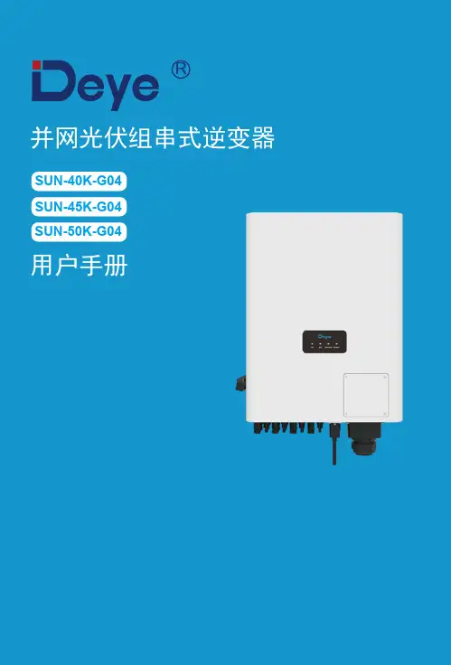
德业SUN-40K-G04、SUN-45K-G04、SUN-50K-G04并网光伏组串式逆变器用户手
目录1. 简介 - 02 -…………………………………………………………………… 1.1 外观说明 - 02 -……………………………………………………………2. 安全警告与说明- 04 - ……………………………………………………… 2.1 安全标识- 04 -…………………………………………………………… 1.2 装箱清单- 03 -…………………………………………………………… 2.2 安全说明- 04 -……………………………………………………………3.操作界面- 06 -……………………………………………………………… 2.3 使用注意事项- 05 -……………………………………………………… 3.2 状态指示灯- 06 -………………………………………………………… 3.1 界面视图- 06 -……………………………………………………………4. 产品安装- 08 -……………………………………………………………… 4.1 选择安装位置 - 08 -………………………………………………………5. 电气连接- 11 -……………………………………………………………… 5.1 直流输入端连接- 11 -………………………………………………… 5.2 交流输出端连接- 13 -…………………………………………………… 5.3 地线连接- 15 -…………………………………………………………… 4.2 逆变器安装- 10 -…………………………………………………………- 16 -……………………………………………………… 5.4 交流断路器 5.5 逆变器监控连接- 16 -……………………………………………………- 17 - 5.6 数据采集器的安装…………………………………………………6. 启动和关闭- 18 -……………………………………………………………7. 电表接线图(该功能仅适用于定制机型)- 19 -…………………………… 6.1 启动逆变器- 18 -………………………………………………………… 6.2 关闭逆变器- 18 -…………………………………………………………………………………- 22 -8. 如何在监控平台上查看光伏并网电站的负载功率- 23 -……………………………………………………………9. 维修和维护- 23 -…………………………………………………10. 故障代码与解决方法- 24 -………………………………………………………… 10.1 故障代码- 28 -………………………………………………………………11.技术参数关于本手册本手册主要介绍产品信息及安装、操作和维护。
阳光电源组串式逆变器安装和操作手册说明书
Building 7, No.333 Wanfang Rd, Minhang District, Shanghai, China. 2011122.1 Safety Precautions . . . . . . . . . . . . . . . . . . . . . . . . . . .2.2 Explanations of Symbols . . . . . . . . . . . . . . . . . . . . . . . .3.Installation . . . . . . . . . . . . . . . . . . . . . . . . .3.1 Package . . . . . . . . . . . . . . . . . . . . . . . . . . . . . . . .3.2 Product Overview . . . . . . . . . . . . . . . . . . . . . . . . . . . .3.3 Mounting Location . . . . . . . . . . . . . . . . . . . . . . . . . . .3.4 Installation On-grid PV Inverter . . . . . . . . . . . . . . . . . . . . .3.5 Electrical Connection . . . . . . . . . . . . . . . . . . . . . . . . . .3.5.1 PV Connection . . . . . . . . . . . . . . . . . . . . . . . . . . . .3.5.2 Grid Connection . . . . . . . . . . . . . . . . . . . . . . . . . . .3.5.3 Communication Connection (WIFI / Ethernet / GPRS / RS485) . . . . .4.Operation . . . . . . . . . . . . . . . . . . . . . . . . . .4.1 Control Panel . . . . . . . . . . . . . . . . . . . . . . . . . . . . . .4.2 Menu Structure . . . . . . . . . . . . . . . . . . . . . . . . . . . . .4.3 Setting . . . . . . . . . . . . . . . . . . . . . . . . . . . . . . . . .4.3.1 Startup Setting. . . . . . . . . . . . . . . . . . . . . . . . . . . . .missioning . . . . . . . . . . . . . . . . . . . . . . .6.Shut Down & Restart the Inverter . . . . . . . . . . . . .6.1 Shut Down Procedures . . . . . . . . . . . . . . . . . . . . . . . . .6.2 Restart the inverter . . . . . . . . . . . . . . . . . . . . . . . . . . .7.Maintenance&Trouble Shooting . . . . . . . . . . . . . .7.1 Maintenance . . . . . . . . . . . . . . . . . . . . . . . . . . . . . .7.2 Fault Code and Trouble Shooting . . . . . . . . . . . . . . . . . . .8.Specifications . . . . . . . . . . . . . . . . . . . . . . . .17 18 18 1818 18 18 201.About This Manual1.1 Scope of Validity1.2 Target Group1.3 System DiagramThis manual describes the installation, commissioning, operation andmaintenance of the following on-grid PV inverters produced by Afore NewEnergy:This manual is for qualified personnel. The tasks described in this manual mustonly be performed by qualified personnel.Single-Phase(Two MPPT Trackers)HNS3000TL HNS3600TL HNS4000TL HNS5000TL HNS6000TLSingle-Phase(One MPPT Tracker)HNS3600TL-1Please keep this manual all the time available in case of emergency.About This Manual01The typical connection diagram for the entire PV system is on-grid.W I F I / RS 485Cloud serverPortal webPV Array Circuit Breaker3AC GridPV ArrayPV Inverter2.Safety & Symbols2.1 Safety Precautions1. All work on the inverter must be carried out by qualified electricians.2. The device may only be operated with PV panels.3. The PV panels and inverter must be connected to the ground.4. Do not touch the inverter cover until 5 minutes after disconnecting both DC and AC power supply. Safety & Symbols02Type Max AC Current [A]Rated current of AC breaker[A]Circuit Breaker and Surge Protector Recommendation: SPD: Lightning protection system, refer to the following options: AC side, nominal discharge current 20KA, second grade lightning protection,protection voltage 2.5KVDC side, nominal discharge current 20KA, second grade lightning protection,protection voltage 3.2KV The wiring distance between the inverter and the distribution box should be at least 5 meters.Single-Phase(Two MPPT Trackers)Single-Phase(One MPPT Tracker)HNS3600TL-11825Note:The Inverter can be only connected to low-voltage grid.(220/230Vac, 50/60Hz).5. Do not touch the inverter enclosure when operating, keep away from materials that may be affected by high temperatures.6. Please ensure that the used device and any relevant accessories are disposed of in accordance with applicable regulations.7. Afore inverter should be placed upwards and handled with care in delivery. Pay attention to waterproof. Do not expose the inverter to water, rain, snow or spray.8. Alternative uses, modifications to the inverter not recommended. The warranty can become void if the inverter was tampered with or if the installation is not in accordance with the relevant installation instructions.Afore inverter strictly comply with relevant safety standards. Please read andfollow all the instructions and cautions during installation, operation and maintenance.Safety & Symbols032.2 Explanations of SymbolsImportant NotesRead all instructions carefully. Failure to follow these instructions,3.Installation3.1 PackageUnpackingOn receiving the inverter, please check to make sure the packing and all components are not missing or damaged. Please contact your dealer directly for supports if there is any damage or missing components.Package List Open the package, please check the packing list shown as below.Installation 04Note: The HNS3600TL-1 is 1 pair of DC plug connector, theHNS3000-6000TL is 2 pairs.689101Overview of the Connection AreaThe following picture shows the assignment of the individual connection areas on the bottom of the inverter.Installation053.2 Product OverviewThe inverters are designed for indoor and outdoor installation (IP65), to increase the safety, performance and lifespan of the inverter, please selectthe mounting location carefully based on the following rules: The inverter should be installed on a solid surface, far from flammable or corrosion materials, where is suitable for inverter’s weight and dimensions. The ambient temperature should be within -25℃ ~ 60℃ (between -13 °F and140°F).The installation of inverter should be protected under shelter. Do not expose the inverter to direct sunlight, water, rain, snow, spray lightning, etc.Installation 063.3 Mounting LocationThe inverter should be installed vertically on the wall, or lean back on planewith a limited tilted angle. Please refer to below picture.Installation073.4 Installation On-grid PV Inverter Leave the enough space around inverter, easy for accessing to the inverter, connection points and maintenance.Step 2300mm500mm3.5 Electrical Connection3.5.1 PV ConnectionThe inverter is equipped with 2 MPPT channels, each of which contains a PVstring input. For best results, please ensure that each MPPT channel isconnected to a PV string separately. Otherwise, the inverter will activate voltageor automatic current protection.·The open-circuit voltage and short-circuit current of PV string must not exceed inverter’s range·The isolation resistance between PV string and ground must exceed 10 kΩ·The polarity from PV strings are correct·Use the DC plugs in the accessory·The lightning protector should be equipped between PV strings and inverter ·Disconnect all of the PV (DC) switch during wiringWarning:The fatal high voltage may on the DC side, please comply withelectric safety when connecting.Please make sure the cable connected in correct polarity withinverter, otherwise inverter could be damaged.Installation09Note :It is strongly recommended to connect by two strings of panels for models of two MPPT channels, e.g. HNS3000-6000TL.210 solar panels should connect from PV side A and B as the Y -shaped, setting PV model parallel and PV side voltage notexceed 500V one MPPT; other solar panels we are recommend you though dual MPPT input the cables, also no exceed 450VNote:Please use PV connector crimperNote:You’ll hear click sound whenthe connector assembly is correctNote:PV cable suggestion Cross-section 4 mmThe on-grid PV inverters work with grid (220/230/240 Vac, 50/60 Hz).The external AC switch should be installed between inverter and grid to isolate from grid. Please make sure below requirements are followed before connecting AC cable to the inverter.·The AC (grid) voltage must not exceed inverter’s range·The phase-line from AC distribution box are correctly connected ·Use the AC plugs in the accessory·The surge protector should be equipped between grid and inverter ·Disconnect the AC (grid) switch during wiringInstallation103.5.2 Grid ConnectionWarning:The fatal high voltage may on the AC side, please comply with electric safety when connecting.Please make sure the right line of AC grid connected with inverter, otherwise inverter could be damaged.AC line goes through AC terminal waterproof head and capNote:AC cable suggestion Cross-section4 mm11InstallationConnect AC line, Live line (L), Neutral line (N) and Ground Wire (PE) according to polarity.1. Connect AC terminals and waterproof head, tightenthe cap, make sure they clip closely together.2. Connect AC connector to AC terminal of the inverter.3. Afeer making sure that it is firmly insered, tightenthe sleeve on the AC connector to the right and hear aclick.12Installation3.5.3 Communication ConnectionThe monitoring module could transmit the data to the cloud server, and display the data on the PC, tablet and smart-phone.Install the WIFI / Ethernet / GPRS / RS485 CommunicationWIFI / Ethernet / GPRS / RS485 communication is applicable to the inverter. Please refer to "Communication Configuration Instruction" for detailedinstruction.Installation13For single-phase inverter, please follow below pin order RS485A(Pin 7) to single-phase meter (Pin 24)RS485B(Pin 8) to single-phase meter (Pin 25)4.5 Zero-injection Smart Meter (Optional)Smart meter is an intelligent control equipment which is used for on-grid inverters. Its main function is to measure the forward and reverse power on Note:Operation14Note:The Inverter could be connected in parallel with Smart Meter,make sure the total load power not exceed Smart Mater’s limitation.GridPV InverterPV ArrayPV ArrayPV ArrayNote:Please refer to "Zero InjectionSmart Meter Installation andOperation Manual" for detailed instruction.Operation155.2 Menu StructureSecond Level MenuOperation175.3.3 Frequency RangeMain MenuENTENTENTENTENTENTENTENTNote:The parameters setting only works after the inverter is restarted.ENTENTENTENTENTENTUP/DOWNUP/DOWNUP/DOWNUP/DOWN set protection timeUP/DOWN set level 2UP/DOWNUP/DOWNUP/DOWNUP/DOWN set level 1UP/DOWN set level 2UP/DOWN set level 1UP/DOWNUP/DOWN set protection timeUP/DOWN set level 2UP/DOWNUP/DOWNUP/DOWNUP/DOWN set level 1UP/DOWN set level 2UP/DOWN set level 120Maintenance&Trouble Shooting Trouble-Shooting ListOperation165.3.1 Startup5.3 SettingExplanation of LCD Display Content5.3.2 Voltage RangeMain MenuENTENTUP/DOWNUP/DOWNENTENTUP/DOWN Adjust the time andUP/DOWNCommissioning18Before starting up commissioning at site, please make sure below procedures and requirements are fully meet.• Mounting location is meet the requirements.• All of the electrical wiring is firmly connected, including PV wiring, Grid wiring and Earth wiring.• The inverter setting has been finished accordingly to local standards or regulations.Commissioning Procedures• Turn on the AC switch between inverter output and the public grid;• Turn on the DC switch on the inverter;• Turn on the PV switch of the system.6. Commissioning7. Shut down & restart inverter• Turn off the DC switch on the inverter.• Turn off the DC switch between PV panels and the inverter (if any).• Close the AC switch between the inverter and the public grid.• Shut down the inverter according to Chapter 7.1.• Start-up the inverter according to Chapter 6.7.2 Restart7.1 Shut downNote:The inverter will be operable after minimum 5 minutes.5.Operation 5.1 Control Panel○2○3○1○○45○○○678Operation 15Shut Down & Restart the Inverter19Periodically maintenance are necessary, please follow steps as below. PV connection: twice a yearAC connection : twice a yearEarth connection: twice a yearHeat sink: clean with dry towel once a year.Fault messages will be displayed when fault occurs, please according to trouble- shooting table find related solutions.8. Maintenance&Trouble Shooting8.1 Maintenance8.2 Trouble Shooting21 Maintenance&Trouble Shooting22Maintenance&Trouble Shooting8.Specifications Specifications23Max. DC Power ( W )Max. DC Voltage ( V )MPPT Voltage Range ( V ) MPPT Full Power Voltage Range ( V ) Rated Input Voltage ( V )Start-up Voltage ( V )Max. Input Current ( A )Max. Short Current ( A )No. of MPP Tracker /No. of PV StringInput Connector TypeMax. Output Power ( W ) Nominal Output Power ( W ) Max. Output Current ( A ) Nominal Output Voltage ( V )Grid Voltage Range Nominal Output Frequency ( Hz ) Grid Frequency Range Output Power FactorOutput Current THDMax. EfficiencyEuro Efficiency°C180Vac-276Vac (According to local standard)45~55Hz/54~66Hz (According to local standard)1 default (adjustable from 0.8 leading to 0.8 lagging)L/N/PE, 220Vac, 230Vac, 240VacIntegrated(Type III)RS485 / WiFi / Wire Ethernet / GPRS (op ti onal)EN/IEC 61000-6-2, EN/IEC 61000-6-3, EN61000-3-2, EN61000-3-3, EN61000-3-11, EN61000-3-12IEC 60068, IEEE1547,EN62109PV Reverse Polarity Protection PV Insulation Resistance Detection AC Short Circuit ProtectionAC Over Current ProtectionAC Over Voltage ProtectionAnti-Islanding Protection Residual Current Detection Over Temperature Protection Integrated DC switchSurge ProtectionDimensions (W x H x D, mm) Weight ( kg )Protection Degree Enclosure MaterialAmbient Temperature Range ( ) Humidity RangeTopology Communication Interface Cooling ConceptNoise Emission ( db )Night Power Consumption ( W ) Max. Operation Altitude ( m )EMC StandardSafety StandardGrid-connec ti on3607014 x 218 x 22/2330030001598.20%97.80%YESYESYESYESYESYESYES450060070-550110-550MC43607014 x 218 x 22/23960360017.598.20%97.82%YESYESYESYESYESYESYES4000540060070-550130-550MC43607014 x 218 x 22/2440040002098.20%97.85%YESYESYESYESYESYESYES10<28358×360×142600060070-550145-550MC43607014 x 218 x 22/25500500024<3%50/6098.20%97.90%YESYESYESYESYESYESYESConvection<1IP65AluminumTransformerless0-100%700060070-550180-550MC43607014 x 218 x 22/26600600028.798.20%97.92%YESYESYESYESYESYESYES840060070-550220-550MC4YES YES YES YES YESYES YES YES YES YES 3960360017.598.20%97.80%3607014181/1420060070-500130-500MC4YESYESYESYESYESYESYESYESYES-25 ~ +60°C (Derating 45°C)EN50549-1, EN50438, RD 1699,UNE 217001, RD 413, IEC61727, IEC62116, IEC61683, VDE4105, UL1741 VDE0126 AS4777.2 NB/T 32004-2018, UNT C 15-712-1, ABNT NBR 16149, ABNT NBR 16150。
华为组串式逆变器
华为组串式逆变器智能●最多8路高精度智能组串检测,减少故障定位时间80%;●多机并联智能电网自适应,电能优质,更好地满足电网接入要求;●华为专用无线通信技术,无需专用通讯线缆。
高效●最高效率99%,中国效率98.49%;●无N线,可节省20%交流线缆投资;●最多4路MPPT,适应复杂的屋顶环境,发电量提升5%以上。
安全●安全的规避PID效应,主动防止触电并隔离;●无熔丝设计,避免直流侧故障引起的火灾隐患;●零电压穿越,满足电网接入要求。
可靠●25年设计使用寿命;●自然散热,IP65防护等级;●内置交直流防雷模块,全方位雷击保护。
1、做工精细 华为SUN2000组串式光伏逆变器采用最优质的材料和最先进的工艺制造,通讯只需连接普通网线(RS485线)即可实现;操作简单,容易上手,三相接线简单,接上铜鼻子即可。
2、顶级配置华为逆变器最多4路MPPT ,比很多其他品牌逆变器多1~2路,更好地解决了电池板的朝向及遮挡问题,提升发电量5%以上;最多配有2个直流开关,在检测或维修时保证绝对安全;最高效率99%,显著提升发电量。
3、屏显简洁 =[表示直流,]~表示交流,第三个图标表示485通讯,第四个图标表示工作状态;第一、二个指示灯绿时,表示逆变器工作正常,可以并网发电;第三个指示灯绿时,表示通讯正常。
4、自然散热采用全密闭自然散热设计,利用热隔离、热屏蔽技术,将发热器件和热敏感器件分腔合理布局,确保整机无局部热点,提升散热可靠性,解决了因风扇失效散热能力降低导致的功率降低,发电量减少的问题。
5、安装方便 华为逆变器体积小、重量轻,每台逆变器尺寸约550*700*250mm ,重量<60kg ,两个人10分钟就可完成安装;且支持整机更换,故障设备返厂维修,现场无需专家;单台逆变器故障对光伏系统发电影响小。
6、蓝牙监控华为独有的蓝牙模块可通过逆变器下端的USB 接口与移动设备连接,实现近端的发电数据采集与分析,以及逆变器操作系统的更新升级。
组串式逆变器直流侧的结构-概述说明以及解释
组串式逆变器直流侧的结构-概述说明以及解释1.引言概述部分应对读者简单介绍组串式逆变器直流侧的结构,解释其基本原理和重要性。
以下是概述部分的内容示例:【1.1 概述】组串式逆变器是一种应用广泛的电力电子设备,其在可再生能源发电系统中具有重要作用。
作为太阳能光伏电池系统中的核心部件,组串式逆变器负责将光伏电池板产生的直流电转换为交流电,并将其注入到电网中。
组串式逆变器直流侧的结构是实现这一电能转换过程的关键。
它主要由直流输入端子、输入滤波电路、直流电压变换电路和直流电压调节电路等组成。
在实际应用中,我们常常会遇到不同功率的光伏电池板,而组串式逆变器直流侧的结构要点就在于能够适应不同功率的光伏电池板,使得电能转换过程更加稳定高效。
组串式逆变器直流侧的结构要点旨在解决以下几个关键问题:首先,如何确保光伏电池板的直流电能能够与逆变器直流输入端子相连接,实现电能的传输;其次,如何设计有效的输入滤波电路,以减小直流电压中的噪声和干扰;第三,如何通过直流电压变换电路实现输入直流电压的变换,以适应不同功率的光伏电池板;最后,如何利用直流电压调节电路实现对直流电压的精确控制,以提高电能转换效率和安全性。
本文将详细探讨组串式逆变器直流侧的结构要点,包括其中的关键技术和设计考虑。
通过深入了解组串式逆变器直流侧的结构要点,我们能够更好地理解其工作原理,并为其应用和改进提供有益的参考。
1.2文章结构文章结构部分是整篇文章的框架,它的目的是为读者提供一个清晰的指引,使其能够更好地理解文章内容。
本文的文章结构如下:1. 引言1.1 概述1.2 文章结构(即本部分)1.3 目的2. 正文2.1 组串式逆变器的基本原理2.2 组串式逆变器直流侧的结构要点(即本部分)3. 结论3.1 总结3.2 展望在本文中,我们将首先在引言部分概述组串式逆变器的基本原理和其在实际应用中的重要性。
接下来,我们将详细讨论组串式逆变器直流侧的结构要点,包括其组成部分、工作原理以及设计考虑等。
集中式逆变器和组串式逆变器之比较
集中式逆变器和组串式逆变器之比较——深圳恒通源1、逆变器方案对比(1)集中式逆变器:设备功率在50KW到630KW之间,功率器件采用大电流IGBT,系统拓扑结构采用DC-AC一级电力电子器件变换全桥逆变,工频隔离变压器的方式,防护等级一般为IP20。
体积较大,室内立式安装。
(2)组串式逆变器:功率小于30KW,功率开关管采用小电流的MOSFET,拓扑结构采用DC-DC-BOOST升压和DC-AC全桥逆变两级电力电子器件变换,防护等级一般为IP65。
体积较小,可室外臂挂式安装。
2、系统主要器件对比(1)集中式逆变器:光伏组件,直流电缆,汇流箱,直流电缆,直流汇流配电,直流电缆,逆变器,隔离变压器,交流配电,电网。
(2)组串式逆变器:组件,直流电缆,逆变器,交流配电,电网。
3、主要优缺点和适应场合(1)集中式逆变器一般用于日照均匀的大型厂房,荒漠电站,地面电站等大型发电系统中,系统总功率大,一般是兆瓦级以上。
主要优势有:●逆变器数量少,便于管理;●逆变器元器件数量少,可靠性高;●谐波含量少,直流分量少电能质量高;●逆变器集成度高,功率密度大,成本低;●逆变器各种保护功能齐全,电站安全性高;●有功率因素调节功能和低电压穿越功能,电网调节性好。
主要缺点有:●直流汇流箱故障率较高,影响整个系统。
●集中式逆变器MPPT电压范围窄,一般为450-820V,组件配置不灵活。
在阴雨天,雾气多的部区,发电时间短。
●逆变器机房安装部署困难、需要专用的机房和设备。
●逆变器自身耗电以及机房通风散热耗电,系统维护相对复杂。
●集中式并网逆变系统中,组件方阵经过两次汇流到达逆变器,逆变器最大功率跟踪功能(MPPT)不能监控到每一路组件的运行情况,因此不可能使每一路组件都处于最佳工作点,当有一块组件发生故障或者被阴影遮挡,会影响整个系统的发电效率。
●集中式并网逆变系统中无冗余能力,如有发生故障停机,整个系统将停止发电。
(2)组串式逆变器适用于中小型屋顶光伏发电系统,小型地面电站。
逆变器快速安装指南
逆变器快速安装指南本安装指南适用于Suntrio Plus 4K/5K/6K/8K/10K 逆变器 一、逆变器配件二、安装方式及间隙图2.1安装方式80cm30cm80cm80cm80cm80cm30cm5cm5cm图2.2安装间隙三、挂板尺寸及钻孔图2.1挂板尺寸图2.2安装间隙四、安装逆变器图4.1挂板固定图4.2挂装逆变器图4.3固定逆变器和挂板 逆变器 挂板 DC连接器 RS485连接器1台 1块Suntrio Plus4K/5K/6K 2对Suntrio Plus8K/10K 3 对1个M6×50六角螺钉及垫片螺丝固定座M5×12 内六角圆柱头螺丝和垫圈AC连接器3个 3个 2个 1个五、交流侧电气连接导线横截面积(mm²)线缆外径范围(mm) 范围 推荐值4.0-6.0 6.0 4.2~5.3表5.1 交流侧电气连接图5.1将电缆穿过快速连接器图5.2对照相应位置连接电缆图5.3拧紧连接器各部位图5.4将接头连接至逆变器图5.5逆变器外壳接地六、直流电缆连接导线横截面积(mm²)线缆外径范围(mm)范围 推荐值4.0-6.0 4.0 4.5-7.8表6.1 推荐直流线缆规格图6.1压接直流电缆图6.2插入接头并拧紧图6.3连接至逆变器七、连接通讯模块图7.1连接通讯模块。