PM300A智能网络仪表说明书V3.1
PM-3 用户手册说明书

PM-3 Planar Magnetic HeadphonesUser ManualContentsImportant Safety Information ‐‐‐‐‐‐‐‐‐‐‐‐‐‐‐‐‐‐‐‐‐‐‐‐‐‐‐‐‐‐‐‐‐‐‐‐‐‐‐‐‐‐‐‐‐‐‐‐‐‐‐‐‐ 2 Introduction ‐‐‐‐‐‐‐‐‐‐‐‐‐‐‐‐‐‐‐‐‐‐‐‐‐‐‐‐‐‐‐‐‐‐‐‐‐‐‐‐‐‐‐‐‐‐‐‐‐‐‐‐‐‐‐‐‐‐‐‐‐‐‐‐‐‐‐‐‐‐‐‐‐‐‐‐ 3 Feature Highlights ‐‐‐‐‐‐‐‐‐‐‐‐‐‐‐‐‐‐‐‐‐‐‐‐‐‐‐‐‐‐‐‐‐‐‐‐‐‐‐‐‐‐‐‐‐‐‐‐‐‐‐‐‐‐‐‐‐‐‐‐‐‐‐‐‐‐‐‐ 4 Using Your Headphones ‐‐‐‐‐‐‐‐‐‐‐‐‐‐‐‐‐‐‐‐‐‐‐‐‐‐‐‐‐‐‐‐‐‐‐‐‐‐‐‐‐‐‐‐‐‐‐‐‐‐‐‐‐‐‐‐‐‐‐‐‐ 5 Specifications ‐‐‐‐‐‐‐‐‐‐‐‐‐‐‐‐‐‐‐‐‐‐‐‐‐‐‐‐‐‐‐‐‐‐‐‐‐‐‐‐‐‐‐‐‐‐‐‐‐‐‐‐‐‐‐‐‐‐‐‐‐‐‐‐‐‐‐‐‐‐‐‐‐‐‐ 7Important Safety InformationBefore using your headphones, make sure to lower the volume level on your headphone amplifier or portable device. Prolonged exposure to high volumes may result in temporary or even permanent hearing loss.Be aware of your surroundings. Using headphones may diminish your ability to hear important ambient sounds. Exercise caution particularly at railroad tracks, crosswalks, or any environment where motor vehicles or bicycles are present.It is always recommended to lower the volume level prior to connecting or disconnecting your headphones.Do not leave your headphones or cables in an area where people or pets might trip over them.Always supervise children who are using these headphones.IntroductionCongratulations! You are now the proud owner of a pair of truly portable closed‐back planar magnetic headphones.The OPPO PM‐3 utilizes a planar magnetic driver that is developed from the driver in our EISA award‐winning PM‐1 headphones. Technological breakthroughs achieved during the PM‐1’s development, such as the 7‐layer double‐side voice coil diaphragm design and FEM‐optimized neodymium magnet system, have enabled OPPO to reduce the weight of the planar magnetic drivers while maintaining excellent sound quality and high sensitivity. The PM‐3 driver’s smaller size and high sensitivity make it especially suitable for portable use, and this driver would not have been possible without the breakthroughs achieved in the PM‐1’s driver design.In the PM‐3’s planar magnetic driver, sound is generated by a very thin and light diaphragm which is driven in a symmetric pull‐push manner, and the magnetic system and conductor patterns have been optimized for maximum sensitivity and consistency. This allows the diaphragm to generate very stable and linear piston‐like vibrations, ensuring phase coherence and high resolution performance with minimal distortion. Featuring a light weight closed back design and easily driven with any smartphone or portable music player, the PM‐3 headphones will enable you to enjoy your favorite music anywhere while being isolated from outside noise.We are proud of the work we have put into these headphones, and we hope they bring you years of enjoyment.Feature Highlights∙Unique planar magnetic driver with FEM‐optimized neodymium magnet system∙7‐layer double‐side voice coil diaphragm∙Excellent sound quality∙High sensitivity and consistency∙Lightweight for portable use∙Comfortable fit for long‐term listening∙Closed‐back noise isolation design∙Selvedge denim carrying case∙Detachable high quality cable∙Optional headphone cable with inline mic and remote controlUsing Your HeadphonesTwo headphone cables have been included with your OPPO PM‐3.The 3 meter main cable terminates with a 3.5 mm connector and a screw‐on 6.35 mm adapter. It is suitable for connecting the PM‐3 to a headphone amplifier, AV receiver, or integrated amplifier. The screw‐on 6.35 mm adapter can be removed if necessary.The 1.2 meter portable cable terminates with a 3.5 mm plug. It can be used to connect the PM‐3 to a portable media player, cell phone, tablet, or other mobile device.Depending on the type of portable cable that you choose when you order the headphones, the cable may have no inline mic and remote control, or have a mic and remote control for Apple devices, or have a mic and remote control for Android devices.For the portable cable with a mic and remote control for Apple devices, the buttons work the same way as buttons on the original Apple EarPods. You can use the buttons to answer phone calls, start or stop music playback, or skip music tracks. Please refer to your Apple device’s user manual for details of these functions.For the portable cable with a mic and remote control for Android devices, the center button allows you to answer or end a call. Additional operations, such as double‐click or press‐and‐hold, may be possible depending on your mobile device. Please consult the user manual of your mobile device for details.Storing Your HeadphonesAfter each use, it is recommended that you place the headphones on a headphone stand. For carrying the headphones with you or for storage, you may remove the cable and fold the headphones flat to put in the selvedge denim carrying case.Caring for Your HeadphonesIn order to clean the headphones, we recommend using a clean, lint‐free cloth. Do not use harsh chemical cleaners or solvents. If necessary, you may lightly dampen the cloth with clean water.The ear pads are made of durable synthetic leather and are not designed to be detached by the end user. Should your headphones require service, please contact OPPO Digital or your place of purchase.SpecificationsHeadphone Specifications Model Name PM‐3Acoustic Principle Closed‐backEar Coupling CircumauralNominal Impedance 26 OhmSensitivity 102 dB in 1 mWClamping Pressure 5 NCables 3m detachable cable (3.5mm & 6.35 mm) 1.2 m detachable cable (3.5 mm)Cable Connectors Output: 3.5mm stereo jackInput: 6.35 mm stereo jack, 3.5 mm stereo jackWeight 320 g (without cable)Accessories Carrying case User ManualDriver SpecificationsDriver Type Planar MagneticDriver Size (Round) 55 mm diameterMagnet System Symmetric push‐pull neodymium Frequency Response InFree‐Field10 – 50,000 HzLong‐Term Max InputPower500 mW according to IEC 60268‐7 Pulse Max Input Power 2 WCE markThis product complies with European Low Voltage (2006/95/CE), Electromagnetic Compatibility (2004/108/EC) and Environmentally‐Friendly Design of Energy‐Related Products (2009/125/EC) Directives when used and installed according to this instruction manual.WEEE symbolCorrect Disposal of This Product. (Waste Electrical & Electronic Equipment) Applicable in the European Union and other European countries with separate collection systems.This marking on the product, accessories or literature indicates that the product and its electronic accessories should not be disposed of with other household waste at the end of their working life. To prevent possible harm to the environment or human health from uncontrolled waste disposal, please separate these items from other types of household waste and recycle them responsibly to promote the sustainable reuse of material resources.。
PM300A智能网络仪表说明书V3.1

40~60Hz,精度±0.02Hz
有功、无功、视在功率,精度±0.5%
-5-
网络仪表 PM300A 系列
电能
开关量 输入 模拟量 输出 (选配) 开关量 输出 (选配)
电度脉冲 输出
(选配)
通讯
辅助电源
环境
安全性 外形 重量
显示 输入形式 隔离电压 输出数量 输出方式 带载能力 输出形式 开关电压 开关电流
iavg网络仪表pm300a系列电度量地址表支持功能码0304读取与功能码10设置地址类型数据定义寄存器40200rw总有功绝对值电度量累计值40202rw总无功绝对值电度量累计值40216ro总正向有功绝对值电度量累计值40226ro总反向有功绝对值电度量累计值40236ro总正向无功绝对值电度量累计值40246ro总反向无功绝对值电度量累计值40256ro象限总无功绝对值电度量累计值40266roiv象限总无功绝对值电度量累计值40276roii象限总无功绝对值电度量累计值40286roiii象限总无功绝对值电度量累计值以上数据ai与实际值之间的对应关系为
二、功能简述
1. 测量和显示:可测量、显示、远传三相电压、有功/无功/视在功率、功率因 数、频率、总绝对值有功电能,总绝对值无功电能,输入绝对值有功电能、 输出绝对值有功电能、输入绝对值无功电能、输出绝对值无功电能、四象限 无功电能(注:电能数值可用作企业内部二级计量管理考核及核算,不作计 量付费使用)。
注意:不执行此说明可能导致人身伤害和死亡。
-2-
网络仪表 PM300A 系列
目录
第一章 概述.................................................................................................. 4 一、用途................................................................................................ 4 二、功能简述........................................................................................ 4 三、选型表............................................................................................ 5 四、技术指标........................................................................................ 5 五、电磁兼容性.................................................................................... 6
PM3000A电力分析仪操作

PM3000A电力分析仪操作介绍PM3000A电力分析仪是一款功能强大的仪器,广泛应用于电力系统的分析和测试。
本文将介绍PM3000A电力分析仪的基本操作方法和常用功能。
操作步骤以下是PM3000A电力分析仪的基本操作步骤:1. 连接电源和被测电路首先,将PM3000A电力分析仪连上电源,并使用连接线将被测电路与仪器进行连接。
确保连接线的接触良好,以确保精确的测量结果。
2. 打开电力分析仪按下电力分析仪的电源按钮,待其开机启动完毕。
3. 设置测量参数在主界面上,您可以看到多个测量参数选项。
按照您的需求,选择相应的参数进行测量。
例如,您可以选择测量电压、电流、功率因数等。
4. 进行实时测量一旦设置好测量参数,您可以开始进行实时测量。
通过观察仪器的显示屏,您可以实时查看被测电路的电力参数。
如果需要,您还可以将这些数据记录下来,以便后续分析。
5. 分析测量结果PM3000A电力分析仪还具备数据分析功能。
您可以使用仪器提供的分析工具来分析测量结果。
例如,您可以生成报表、绘制曲线图等。
常用功能1. 仪器校准为确保测量结果的准确性,定期进行仪器校准非常重要。
PM3000A 电力分析仪提供了自动校准功能,您可以按照仪器的提示进行操作。
2. 数据存储和传输PM3000A电力分析仪可以将测量数据存储到内部存储器中,也可以通过USB接口将数据传输到电脑或其他存储设备。
这样,您可以随时随地方便地查看和分析测量数据。
3. 功率因数测量PM3000A电力分析仪支持功率因数测量,可以帮助您分析系统的功率因数及其对电力质量的影响。
通过实时测量和数据分析,您可以优化电力系统的功率因数,并采取相应的措施来提高电力质量。
4. 功率波形分析除了基本的电力参数测量外,PM3000A电力分析仪还具备功率波形分析功能。
通过对功率波形的分析,您可以了解电力系统中的谐波情况,并采取相应的措施来减少谐波对系统的影响。
总结通过本文的介绍,您已了解PM3000A电力分析仪的基本操作方法和常用功能。
三相多功能网络仪表用户手册

三相多功能网络仪表用户手册1.产品简介本系列多功能仪表是一种具有可编程测量显示,数字通讯和电能脉冲输出等多功能仪表,能够完成电量测量,电能计量数据显示,采集及传输,可广泛用于变电站自动化,配电自动化,智能建筑,企业内部的电能测量管理,考核.实现LED 现场显示和远程RS485数字通讯接口,2路电能脉冲输出和1~4路模拟量4-20MA ,可实现电能和电量变送输出功能, 1~4路开关量输入和输出可实现本地或远程的开关信号的监测和控制功能(“遥信”和”遥控”功能),可组合实现多个电量参数报警及自动控制功能,采用MODBUS- RTU 通讯协议。
2.技术参数性能参数网络三相三线、三相四线额定值AC100V 、400V (订货时请说明)过负荷持续:1.2倍 瞬时:10倍/10s功耗<1VA(每相)阻抗>500KΩ电压精度RMS 测量,精度等级0.5额定值AC1A 、5A (订货时请说明)过负荷持续:1.2倍 瞬时:10倍/10s 功耗<0.4VA(每相)阻抗<2mΩ电流精度RMS 测量,精度等级0.5频率40~60Hz ,精度0.1Hz 功率有功、无功,精度1.5级电能四象限计量,有功精度1.5级,无功精度2级输入测量显示显示可编程、切换、循环(LED )显示工作范围AC/DC 85~270V电源功耗≤5VA 输入开关量输入2~4路数字接口RS-485、MODBUS-RTU 协议脉冲输出2路电能脉冲输出 开关量输出2~4路,继电器输出输出模拟量输出1~3路4-20MA工作环境-10~55℃环境储存环境-20~75℃耐压输入电源>2KV,输入输出>2KV ,电源输出>1KV安全绝缘输入、输出、电源对机壳>5MΩ三相四线电流经CT输入电压直接输入三相四线电流经CT输入电压经PT输入三相三线电流经CT输入电压直接输入三相三线电流经CT输入电压经PT输HUD96(外形94×94×75mm 开孔91×91mm)注意可设置DISP控制字用来编程设置通常状态下显示内容,DISP=1(三相电压),2(三相内容键盘的编程操作采用四个按键的操作方式,即左右移动键“←”“→”、菜单进入或上回退键“Menu”、选择确定键“”来完成上述功能的所有操作。
Omega HHM-MG300 无线真值多功能电阻抗性计量器与绝缘电阻测试仪说明书

e-mail:**************For latest product manuals:HHM-MG300Wireless TRMS Multimeterand Insulation TesterShop online at ®User’s GuideMADE IN TAIWANIt is the policy of OMEGA Engineering, Inc. to comply with all worldwide safety and EMC/EMI regulations that apply. OMEGA is constantly pursuing certification of its products to the European New Approach Directives. OMEGA will add the CE mark to every appropriate device upon certification.The information contained in this document is believed to be correct, but OMEGA accepts no liability for any errors it contains, and reserves the right to alter specifications without notice.WARNING: These products are not designed for use in, and should not be used for, human applications.HHM-MG300Wireless TRMS Multimeter and Insulation TesterSoftware IntroductionThe MultiMeter software is a program for collecting data from the meter when it is connected to a Desktop or Notebook PC(Personal Computer). The data may be displayed graphically within this software application or may be export to spreadsheet software programs. The softwareʼs functions are presented in the main window.The maximum number of data points that can be captured is 20,000. Supported Operating Systems:Windows 2000/Windows XP /Vista/Windows 7Minimum Hardware Required:•Desktop or Notebook PC with a minimum clock speed of 90MHz•32 MB RAM•7 MB hard disk space•Monitor display resolution of 1280 x 1024 with High Color (32 bit)Main Menu•FileSave Save the recorded data to the PCOpen Open a file previously saved on the PCPrint Setup Modify the print optionsPrint Preview Preview the data graph or the data listPrint Print the data graph or the data list•ViewToolbar Show or hide the ToolbarStatus Bar Show or hide the Status BarInstrument Show or hide the instrument window •InstrumentReal Time Chart Recording Start collecting real time dataStop Recording Stop collecting real time data•WindowCascade Arrange windows in an overlapping styleTile Arrange windows in a non-overlapping tile style •HelpAbout Show the software version informationHelp Topics Show the software help utilityOperationEnabling Communication1. Switch the meter ON2. Put the meter in the “USB” mode by pressing and holding the meter’s USB buttonfor two seconds (meter will beep when USB mode is accessed)3. Connect the receiver to the PC’s USB port using the supplied cable4. Run the MultiMeter software program5. Double click the small meter icon on the software screen (shown in the diagrambelow). The larger meter image will appear6. If communication is successful, the larger virtual meter image will accuratelyreflect the current state of the meter (shown in diagram below)Downloading Datalogged Information from UnitDownloading data from the Unit to the PC takes a few steps:Do not establish communication prior to downloading data. If there is communicationbetween the unit and the PC unwanted data may be included in the List/Graph of thedatalogged information.1. After the software has been started, Press and HOLD the STORE button for twoseconds to enter the RECALL function. “RCL” will appear on the bottom left of thedisplay2. A real time recording must be initiated before data can be downloaded.Refer to the Real Time Chart Recording section for assistance—recommendedmaximum data points for a real time recording is 8000.3. Press and Hold the HOLD button for two seconds and the data will be transferred to thePC.4. The data will form a graph and a data list in the software’s main window.Real Time Chart Recording1. Click to open the Sampling Setup dialog box as shown below.2. Enter the desired number of samples to record and then click “OK”. The data willbegin plotting on the graph (as shown below).Custom Scale: Configure the vertical scale.•Enter the minimum scale value in the minimum edit box (as shown above). •Enter the maximum scale value in the maximum edit box.Auto scale: Select Auto Scale to allow the vertical scale to be automatically configured based on the data plot.Custom scale: Select Custom Scale to configure the vertical scale as described above. Graph Format: Configure the graph and data format.The “Data Visible” check box allows the user to show/hide the data on the graph.The HORIZONTAL and VERTICAL check boxes allow the user to add/remove grid lines from horizontal and vertical axis.The “Mark Points” feature shows the individual data points on the graph.“Save the setting” allows the user to save the settings with the document.Click these buttons in the Graph Format window to open the color selector chart for the related feature (the color chart is shown below).Zoom in: When the ZOOM IN icon is selected, the icon will highlight1. Press the left mouse button and drag a rectangle around the area to beexpanded.2. Release the mouse button.3. Use the scrollbar to scroll through the data.Zoom out: Zoom out to the full view by clicking.Cursor: When the cursor icon is selected, the icon will highlight When the cursor mode is selected:•Click a data point on the graph to indicate its value.•Click on or near a data point to indicate the value of the data point. The data point selected can be changed by navigating the cursor or by: •Using the clicking method.•Clicking and dragging the mouse horizontally in the graph..Click the “Data List” Tab to open the Data List window (as shown below).File Save and File Open1. Click the icon to open the file save dialog box.2. Name the file and save it using the default extension. The file will be saved withthe “.recorder” extension to be reopened in the Multimeter software program and also as a “.xls” file to be opened in a spreadsheet program.3. To open an existing data file for viewing on the data graph window, click on theicon and select a “. recorder” document.Print graph and listPrint Setup:Print Preview: Preview the data graph or the data list. Print: Print the graph or the list.WARRANTY/DISCLAIMEROMEGA ENGINEERING, INC. warrants this unit to be free of defects in materials and workmanship for a period of 13 months from date of purchase. OMEGA’s WARRANTY adds an additional one (1) month grace period to the normal one (1) year product warranty to cover handling and shipping time. This ensures that OMEGA’s customers receive maximum coverage on each product.If the unit malfunctions, it must be returned to the factory for evaluation. OMEGA’s Customer Service Department will issue an Authorized Return (AR) number immediately upon phone or written request.Upon examination by OMEGA, if the unit is found to be defective, it will be repaired or replaced at no charge. OMEGA’s WARRANTY does not apply to defects resulting from any action of the purchaser,including but not limited to mishandling, improper interfacing, operation outside of design limits, improper repair, or unauthorized modification. This WARRANTY is VOID if the unit shows evidence of having been tampered with or shows evidence of having been damaged as a result of excessive corrosion;or current, heat, moisture or vibration; improper specification; misapplication; misuse or other operating conditions outside of OMEGA’s control. Components in which wear is not warranted, include but are not limited to contact points, fuses, and triacs.OMEGA is pleased to offer suggestions on the use of its various products. However, OMEGA neither assumes responsibility for any omissions or errors nor assumes liability for any damages that result from the use of its products in accordance with information provided by OMEGA, either verbal or written. OMEGA warrants only that the parts manufactured by the company will be as specified and free of defects. OMEGA MAKES NO OTHER WARRANTIES OR REPRESENTATIONS OF ANY KIND WHATSOEVER, EXPRESSED OR IMPLIED, EXCEPT THAT OF TITLE, AND ALL IMPLIED WARRANTIES INCLUDING ANY WARRANTY OF MERCHANTABILITY AND FITNESS FOR A PARTICULAR PURPOSE ARE HEREBY DISCLAIMED. LIMITATION OF LIABILITY: The remedies of purchaser set forth herein are exclusive, and the total liability of OMEGA with respect to this order, whether based on contract, warranty, negligence, indemnification, strict liability or otherwise, shall not exceed the purchase price of the component upon which liability is based. In no event shall OMEGA be liable for consequential, incidental or special damages.CONDITIONS: Equipment sold by OMEGA is not intended to be used, nor shall it be used: (1) as a “Basic Component” under 10 CFR 21 (NRC), used in or with any nuclear installation or activity; or (2) in medical applications or used on humans. Should any Product(s) be used in or with any nuclear installation or activity, medical application, used on humans, or misused in any way, OMEGA assumes no responsibility as set forth in our basic WARRANTY /DISCLAIMER language, and, additionally, purchaser will indemnify OMEGA and hold OMEGA harmless from any liability or damage whatsoever arising out of the use of the Product(s) in such a manner.RETURN REQUESTS/INQUIRIESDirect all warranty and repair requests/inquiries to the OMEGA Customer Service Department. BEFORE RETURNING ANY PRODUCT(S) TO OMEGA, PURCHASER MUST OBTAIN AN AUTHORIZED RETURN (AR) NUMBER FROM OMEGA’S CUSTOMER SERVICE DEPARTMENT (IN ORDER TO AVOID PROCESSING DELAYS). The assigned AR number should then be marked on the outside of the return package and on any correspondence.The purchaser is responsible for shipping charges, freight, insurance and proper packaging to prevent breakage in transit.FOR WARRANTY RETURNS, please have thefollowing information available BEFOREcontacting OMEGA:1.Purchase Order number under which the productwas PURCHASED,2.Model and serial number of the product underwarranty, and3.Repair instructions and/or specific problemsrelative to the product.FOR NON-WARRANTY REPAIRS,consult OMEGA for current repair charges. Have the following information available BEFORE contacting OMEGA:1. Purchase Order number to cover the COST of the repair,2.Model and serial number of the product, and 3.Repair instructions and/or specific problems relative to the product.OMEGA’s policy is to make running changes, not model changes, whenever an improvement is possible. This affords our customers the latest in technology and engineering.OMEGA is a registered trademark of OMEGA ENGINEERING, INC.© Copyright 2012 OMEGA ENGINEERING, INC. All rights reserved. This document may not be copied, photocopied,reproduced, translated, or reduced to any electronic medium or machine-readable form, in whole or in part, without theprior written consent of OMEGA ENGINEERING, INC.Where Do I Find Everything I Need for Process Measurement and Control?OMEGA…Of Course!Shop online at SMTEMPERATUREⅪߜThermocouple, RTD & Thermistor Probes, Connectors, Panels & AssembliesⅪߜWire: Thermocouple, RTD & ThermistorⅪߜCalibrators & Ice Point ReferencesⅪߜRecorders, Controllers & Process MonitorsⅪߜInfrared PyrometersPRESSURE, STRAIN AND FORCEⅪߜTransducers & Strain GagesⅪߜLoad Cells & Pressure GagesⅪߜDisplacement TransducersⅪߜInstrumentation & AccessoriesFLOW/LEVELⅪߜRotameters, Gas Mass Flowmeters & Flow ComputersⅪߜAir Velocity IndicatorsⅪߜTurbine/Paddlewheel SystemsⅪߜTotalizers & Batch ControllerspH/CONDUCTIVITYⅪߜpH Electrodes, Testers & AccessoriesⅪߜBenchtop/Laboratory MetersⅪߜControllers, Calibrators, Simulators & PumpsⅪߜIndustrial pH & Conductivity EquipmentDATA ACQUISITIONⅪߜData Acquisition & Engineering SoftwareⅪߜCommunications-Based Acquisition SystemsⅪߜPlug-in Cards for Apple, IBM & CompatiblesⅪߜData Logging SystemsⅪߜRecorders, Printers & PlottersHEATERSⅪߜHeating CableⅪߜCartridge & Strip HeatersⅪߜImmersion & Band HeatersⅪߜFlexible HeatersⅪߜLaboratory HeatersENVIRONMENTALMONITORING AND CONTROLⅪߜMetering & Control InstrumentationⅪߜRefractometersⅪߜPumps & TubingⅪߜAir, Soil & Water MonitorsⅪߜIndustrial Water & Wastewater TreatmentⅪߜpH, Conductivity & Dissolved Oxygen InstrumentsM5139/0612。
ME-300A使用说明书
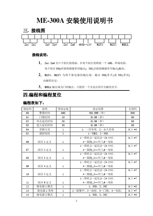
ME-300A安装使用说明书三. 接线图接线说明:1.Zn1_Zn6为六个防区接线端,在每个防区需跨接一个10K,终端电阻,每个防区NO(串联探测器常闭输出),NC(并联探测器常开输出)触发;2.RL Y1,RL Y2为两个继电器的输出端,输出NO(常开)或NC(常闭) 由编程决定;3.BELL输出端为门铃输出,只提供一个无电压的开关触发信号。
四.编程和编程复位编程表如下:系统需在撤防状态1.按“Prog”键;2.输入主码,按“#”键确认(如输入正确,撤/布防灯交替慢闪,提示处于编程地址码输入状态;如输入主码错误,则系统回到正常状态;3.输入编程地址码,按“#”键确认,布/撤防灯交替快闪(提示输入该地址码的编程数据);4.输入该地址码的编程数据,按“#”键确认,如输入正确,系统发出“嘟”的长声并自动跳回地址输入状态(撤防灯交替慢闪);如果输入错误,系统会发出四下短暂的“嘟”声提示无效,保持该地址的原设定值并自动跳回地址输入状态。
地址码00的设定值为三位数;01—03设定值为两位数;04—14设定值为一位数;密码为4—6位数。
5.如输入过程中发现输入错误,可按“*”退回到编程地址码输入状态(撤防灯交替慢闪),重新输入正确的地址码和数据,再按“#”确认;6.退出编程,按“*”键一次或两次,直到撤防灯长亮。
编程步骤摘要:A 按“Prog”键和输入主码,按“#”进入编程(撤防灯交替慢闪);B.输入编程地址码,按“#”键确认(布防灯交替快闪);C.输入编程数据,按“#”键确认(撤防灯交替慢闪);D.按“*”回到编程地址码输入状态或退出编程7.主码恢复:关电源,短路复位跳线,上电后听到连续的提示声,拔掉复位跳线即可。
五. 防盗功能操作1.外出布防:A.输入主码或客码,按“#”确认(如输入的密码正确且无延迟防区,系统立即进入布防状态,撤防灯灭,布防灯亮);B.如果有延迟防区,系统发出延迟声(撤防灯与延迟声同节奏闪动)并在最后15秒声音的速度加快。
iFIX 系统配置指南
iFIX 系统配置指南针对各种项目需求,为了帮助系统工程师和售前服务工程师更好地使用iFIX 及其组件配置企业级系统,本材料在各个方面给出了详尽的说明和例子,以便项目相关人员使用参考。
本材料所涉及的方面主要有如下几个主题:设备连接、iFIX 功能模块选取及数据库设计、网络设计、企业信息系统和资源调度系统集成及冗余系统设计。
第一章设备连接设备连接是一个工厂数据采集系统需要解决的首要问题,iFIX 可以提供与世界上各种知名设备的方便连接方式,同时提供通讯程序的开发工具包以使用户能将自行开发的非标设备连接到 iFIX 监控系统。
下面分几个方面阐述。
1.连接设备类型:iFIX 可以连接的设备种类有很多,主要类型有:DCS、PLC、控制器、远程模块、现场总线设备、条码阅读器、智能仪表、称重仪、其它计算机系统或特殊设备。
2.连接方式:iFIX 和设备的连接方式主要有如下几种:通过串行口连接,通过工业网络连接,通过标准以太网连接,其它方式如:电话拨号,微波设备,无线电传输,专线连接等。
3.使用的 iFIX 驱动程序:iFIX 驱动程序根据开发工具不同,分为 6.x 版本和7.x版本。
6.x版本的驱动程序使用驱动程序开发包 ITK 开发,可以在 WINDOWS95/98 和 WINDOWS NT 上运行。
6.x版本的驱动程序支持在同一台 PC 机上同时运行 8 个不同的驱动程序连接8 种不同设备。
驱动程序内置冗余功能,详见冗余系统描述。
7.x版本的驱动程序使用 ASDK或 OSDK ( OPC Toolkit)开发,只能在WINDOWS NT平台上运行。
7.x版本驱动程序提供 OLE Automation 界面,可以脱离 iFIX 单独运行,并能在 VB程序中引用其属性、方法。
此驱动程序采用 COM/DCOM技术,可以以 C/S结构安装运行。
即可以进行网络远程控制,如将 Client 部分安装在 iClient 上,通过网络控制 Server 部分的运行,进行远程驱动程序组态,控制运行及状态诊断。
AMI 300 AMI 300多功能空气质量分析仪说明书
AMI 300Multifunctional IAQ AnalyzerThe ALL-IN-ONE TOOL.......ConnectionInterchangeablemeasurement modules1 instrument = more than 1 range and 1 parameter available.Wireless connectionInstrument / PC Instrument / ProbeSmart-plus systemProbes automatically recognized whenconnected to the instrument.AMI 300 - Build Your Own KitPa++Dimensions (mm)Side viewFront view 185.4Supplied withCalibrationcertificateFunctions Multi-parameters recordingManual and automatic storage Memory : up to 12,000 measurement points or 50 datasets User-friendly with printing of customized report Management of instruments pool, follow-up of calibration periods Intervention planning Wired or wireless interfaceAdjustable ranges Minimum / maximum values and hold function StorageSelection of units Minimum / maximum values and hold function StorageAIR QUALITY PROBES Audible Alarm (2 setpoints) CO maximum Selection of units Minimum / maximum values and hold functionStorageCLIMATIC CONDITIONS MODULEThermocouple module, Pt100 and thermocouple temperature probes Dynamic delta T Selection of units Minimum / maximum values and hold function Alarme (upper and lower setpoints) StoragePRESSUREAutomatic or manual self-calibration Selection of units Pressure integration (0 to 9) Point/point, automatic point/point, automatic average Minimum / maximum values, Hold, standard deviation StorageAIR VELOCITY AND AIRFLOWSelection of Pitot tube, Debimo blades, Hot-Wire orfactor for other sensing elements Selection of duct type Selection of units Point/point, automatic point/point, automatic average Manual or automatic temperature balancing Manual air pressure balancing K2 factor Minimum / maximum values, hold, standard deviation StorageHYGROMETER Selection of units Minimum / maximum values and hold function StoragePSYCHROMETER Dew point, wet temperature, enthalpy, absolute temperature Minimum / maximum values and hold function StorageWBGT indexFor hygrometry probe with black ball. Calculation of comfort index inside / outside StorageTechnical featuresDatalogger-10Sensing elementsPressure modules Piezoresistive sensorOverpressure allowed ±500 Pa : 250 mbar Overpressure allowed ±2500 Pa : 500 mbar Overpressure allowed ±10,000 Pa : 1,200 mbar Overpressure allowed ±500 mbar : 2 bar Overpressure allowed ±2,000 mbar : 6 barHotwire : Thermistance with a negative temperature coefficient. Ambient temperature : Pt100 1/3 Din.Ø 70 and 100 mm vane probes : Hall effect sensor Ambient temperature : Pt100 class A.Ø 14 mm vane probe : Proximity sensor Ambient temperature : Pt100 class A.Hygrometry/Temp. Probe : capacitive sensor, Pt100 1/3 DIN Thermocouple probes : type K, J and T class 1Pt100 probes Smart-plus : Pt100 class 1/3 Din Climatic conditions moduleHygrometry : capacitive sensor Temperature : semiconductor sensor Air pressure : piezoresistive sensorAir quality probesCO 2 : NDIR sensorCO : electrochemical sensor Temperature : Pt100 class A Hygrometry : capacitive sensorClimatic conditions moduleHygrometry : capacitive sensorTemperature : semiconductive sensor Air pressure : piezoresistive sensorMultifunction probeAir velocity : Thermistance with a negative temperature coefficient.Hygrometry/Temp.: capacitive sensor, Pt100 1/3 DINTachometry probeOptical : optical sensorContact : optical probe with ETC adaptor Instrument connectionsOn the top :2 secured mini-DIN connectors for SMART-Plus probes Left side :1 USB port for EIG cable only 1 power supply plug Module connectionsT hermocouple4 inputs for compensated miniatureplug of thermocouple type K, J or T Class 1(as per IEC 584-3norm) Pressure2 pressure connectors Ø 6.2 mm made of nickelled brass. 2 threaded pressure connectors Ø 4.6 mm made of nickelled brass+ 1 thermocouple temperature input for miniature connectorsCurrent / voltage module 2 stereo jacksDisplayGraphic display 320x240 pixels Dim. 70 x 52 mm, color displayDisplay of 6 measurements (including 4 simultaneously)HousingIP54, ABS shock-proofKeypad Metal-coated, 5 keys, 1 joystick ConformityElectromagnetical compatibility (NF EN 61326-1 norm)Power supply4 alkaline batteries 1.5V LR6 Included Operating environment Neutral gasOperating temperature from 0 to 122°F (0 to 50°C)Storage temperature from 0 to 176°F (-20 to +80°C)Auto shut-off adjustable from 0 to 120 min Weight 13.4 oz. (380g)LanguagesEnglish, French, Dutch, German, Italian, Spanish, Portuguese, Swedish, Norwegian, Finn, DanishSpecificationsInH 2O, Pa, mmH2O,mbar, hPa, mmHg, DaPaV, mAfrom 0 to ±500 Pa from 0 to 2.5 V from 0 to 10 Vfrom 0 to 4/20 mA from 0 to ±2500 Pa 1Pa from 0 to ±10,000 Pa 1Pa CURRENT/VOLTAGEPRESSUREfrom -200 to +1,300°C from -100 to +750°C from -200 to +400°C 0.1 °C 0.1 °C 0.1 °C °C, °FK :J :T :Measuring UnitsMeasuring RangeAccuracy*Resolutions*All accuracies indicated in this document were stated in laboratory conditions and can be guaranteed for measurements carried out in the same conditions, or carried out with required compensation. **The accuracy is expressed either by a deviation in °C, or by a percentage of the value concerned. Only the bigger value is considered.m/s, fpm, Km/h, mph from 2 to 5 m/s from 5.1 to 100 m/s ±0.3 m/s±0.5% of reading ±0.2m/s 0.1 m/s from 0 to 99,999m 3/h ±0.2% of reading ±1% PE 1 m 3/h m 3/h, cfm, l/s, m 3/s Air velocityAirflowAirflowAir velocitym/s, fpm, Km/h, mph from 4 to 20 m/s from 21 to 100 m/s±0.3 m/s±1% of reading ±0.1m/s 0.1 m/s 0.1 m/s from 0 to 99,999m 3/h±0.2% of reading ±1% PE1 m 3/hm 3/h, cfm, l/s, m 3/sHygro.Air pressure%RH from 5 to 95%RH See datasheet for interchangeablemeasurement modules0.1 % RH from 800 to 1100 hPa 1 hPa Temp.from -20 to +80°C 0.1 °C °C, °F from 0.15 to 3 m/s from 3 to 30 m/s ±3% of reading ±0.03 m/s 0.01 m/s 0.1 m/s m/s, fpm, Km/hAir velocity ±3% of reading ±0.1 m/s TemperatureAirflowfrom -20 to +80°C ±0.3% of reading ±0.25°C0.1 °C °C, °F from 0 to 99,999 m 3/h ±3% of reading ±0.03*area(cm 2)1 m 3/h m 3/h, cfm, l/s, m 3/s 0.01 m/s 0.1 m/s m/s, fpm, Km/hAir velocity TemperatureAirflowfrom -20 to +80°C ±0.4% of reading ±0.3°C 0.1 °C °C, °F from 0 to 99,999 m 3/h ±3% of reading ±0.03*area (cm 2) 1 m 3/h0.1 m/s m/s, fpm, Km/h Air velocity Airflow from 0 to 99,999 m 3/h ±3% of reading ±0.03*area (cm 2) 1 m 3/h m 3/h, cfm, l/s, m 3/sTHERMOCOUPLECLIMATIC CONDITIO NSHOTWIRE - Standard and/or Tele scopic -Ø 100 mm VANE PROBEØ 70 mm VANE PROBE0.1 m/s m/s, fpm, Km/hAir velocity TemperatureAirflowfrom -20 to +80°C ±0.4% of reading ±0.3°C0.1 °C °C, °F from 0 to 99,999 m 3/h ±3% of reading ±0.03*area (cm 2) 1 m 3/h m 3/h, cfm, l/s, m 3/sØ 14 mm VANE PROBEPITOT TUBEDEBIMO blades°C, °F ppm ppm %RH from -20 to +80°C 0.1 °C from 0 to 5000 ppm from 0 to 1,000 ppm from 5 to 95% RH 1 ppm Air quality probes : CO / CO 2 / temperature / Hygrometry0.1 % RH STANDARD HYGROM ETRY probe% RHfrom 3 to 98 %RH0.1 % RH STDRelative humidityAbsolute humidity / enthalpyDew pointAmbient temperatureg/Kg / Kj/Kg 0.1 g/Kg from -50 to +80°C td ±0.6% of reading ±0.5°C td 0.1 °C td °C td , °F td from -20 to +80°C0.1 °CHIGH TEMPERATURE HYGROMETRY prob e% RH from 3 to 98 %RH0.1 %RH Relative humidityDew pointAmbient temperatureg/Kg / Kj/Kg 0.1 g/Kg from -50 to +80°C td 0.1 °C td °C td , °F td from -40 to +180°C0.1 °CPt100 Smart-Plus pro bes (See related data sheet)m 3/h, cfm, l/s, m 3/s+±0.2% of reading ±2Pa ±0.2% of reading ±10Pa 0.001 V 0.01 V 0.01 mA ±2mV ±10mV ±0.01mA±1.1°C or ±0.4% of reading**±0.8°C or ±0.4% of reading**±0.5°C or ±0.4% of reading**hPa See related datasheet ''Portable probes''°C, °F°C, °FH.T±0.3% of reading ±0.25°C See related datasheet ''Portable probes''±0.6% of reading ±0.5°C td ±0.3% of reading ±0.25°CSee related datasheet ''Portable probes''According to temperature and hygrometry measuring rangesAbsolute humidity / enthalpyAccording to temperature and hygrometry measuring rangesTemperaturefrom -20 to +80°C ±0.4% of reading ±0.3°C 0.1 °C °C, °F TemperatureCO 2CORelative humidityMULTIFUNCTION prob es (See datasheet ''P ortable probes'')TACHOMETRY probe (See datasheet ''Por table probes'')from 0 to ±500 mBar 0.1mBar ±0.3% of reading ±0,5mBar from 0 to ±2000 mBar 1mBar±0.3% of reading ±2mBar 1 ppm from 0.25 to 3 m/s from 3 to 35 m/s ±3% of reading ±0,1m/s ±1% of reading ±0,3m/s from 0 to 3 m/s from 3 to 35 m/s ±3% of reading ±0,1m/s ±1% of reading ±0,3m/s ±3% of reading ±0,1m/s ±1% of reading ±0,3m/sfrom 0.8 to 3 m/s from 3 to 40 m/s± 100 Pa : ±0.2% reading ±0.8Pa,beyond ±0.2% reading ±1.5Pa,0.1 Pa from -100 to +100 Pa, 1 Pa beyondSupplied with ...DESCRIPTIONPressure module from 0 to ±500 Pa Pressure module from 0 to ±2500 Pa Pressure module from 0 to ±10000 Pa Pressure module from 0 to ±500 mBar Pressure module from 0 to ±2000 mBar Current / voltage module w/ Cables Thermocouple module Climatic conditions module2x1 m silicone tube Ø 4 x 7 mm * Stainless steel tips Ø 6 x 100 mm *Pitot tube Ø 6mm, lg. 300 mm Pitot tube Ø 6mm, lg. 300 mm T Pitot tube Ø 6mm, lg. 300 mm S Optical tachometry probe ETC adaptor Reflective tape Standard hotwireStraight extension for hotwireTelescopic gooseneck-shaped hotwire SMART-Plus Ø 14 mm vane probeTelescopic SMART-Plus Ø 14 mm vane probe SMART-Plus Ø 70 mm vane probe Wireless Ø 70 mm vane probeSMART-Plus Ø 100 mm vane probe Wireless Ø 100 mm vane probeSMART-Plus standard hygrometry probe Wireless standard hygrometry probeSMART-Plus high temperature hygrometry probe Wireless high temperature hygrometry probe SMART-Plus Pt100 temperature probe Wirelesss Pt100 temperature probe Thermocouple K, J and T probe CO 2 / temperature probeCO / temperature probeCO 2 / temperature / Hygrometry probe Air velocity/ Temperature / Hygrometry probe PC Software, USB Cable & Memory Calibration Certificate Transport caseAMI 300OptionADSAccessories (See related datasheet)Warranty periodInstruments have 1-year guarantee for any manufacturing defect (return to our Service Department).Supplied withDatalogger-10KPIJ 20 – 50 – 100 – 200 - 600RTSCE 300GSTADSRD 300JACCHABNDatalogger-10 PC software for data recording andprocessing. Wired (LPCF) or wireless (LPCR) interface.Ammeter clamp with PVC cable lg. 2m and jack connector.Telescopic extension, length 1 m, bent at 90° for measuring probe.BNF Hotwirecleaning spray Airflow cones(See related datasheet)K 25 - 35 - 75 - 120 - 150Silicone heat conductive grease for temperature probesDebimo airflow blades of different sizesBlack ball Ø 150mm with junction for temperature probe Ø 4.5mm. Furtherdimensions available.Straight extension for hotwire Ø 10 mm. lg. 300 mmSilicone tube & crystal flexible tubeSet of 4 LR6 batteries4 batteries chargerAdaptor for power supply 120 VacHands-free protective coverSee related datasheetSee related datasheet*Supplied w/ ANY choose of Pressure ModulesE Instruments International P: 215-750-1212F: 215-750-1399A: 402 Middletown Blvd, Ste 216, Langhorne, PA 19047。
PM3000A电力分析仪操作
累計积分功能
累加积分功能用來分析能量消耗,可顯示Whr(瓦特小時),VAhr( 伏安小時),VAr-hr(乏小時),Ahr(安培小時),平均功率因素, 和Correction Vars (改正乏) 。累計進行期間,可獨立測量其它 功能。 【W-hr】瓦特小時: 有功能量消耗。 【VA-hr】伏安小時: 視在能量消耗或最大功率消耗。 【VAr-hr】乏小時: 無功能量消耗。 【A-hr】安培小時: 測量安時消耗。 【AV-PF】平均功率因素: 顯示积分累加期間的平均功率因素。 【CORR-VAr】改正乏: 改正平均功率因數所需的VArs值。 按【F】【P】2更改由预设值(1,0)变为目标值。 按【FUND】则顯示基本波成份的消耗能量。可使用【F】【P】
积分器功能菜單
累計积分器功能具备很大的使用弹性而可 允許彈性而可由下述方法来加以控制:
手动控制 /本地控制)
外部控制/遠端控制
內部時序控制
IEEE指令控制
手動觸發积分器
按【INTEGRATOR】鍵進入選單選擇在輸入時間後,按 【START RESET】鍵,將開始執行累計。假如累計執行 ,將連續執行直到【STOP】鍵被按才停止。 輸入時間按【ENTER】,則【INTEGRATION】鍵下LED亮 ,等待按【START RESET】鍵開始執行。 假如介面選擇由列表機輸出,則螢幕顯示將不會改變, 但將自動送到列表機。按【STOP】鍵,則停止累計,假 如選擇列表機,則將自動列印。
【A】 電流
【INRUSH A】 突波電流峰值
【PF】 功率因素 【IMPEDANCE】阻抗
【0】 ~. 【9】 【.】 【kM.】數字鍵与參數選擇鍵。
有功功率,无功功率,与視在功率
選擇【W】并设定输入为(AC+DC)耦合,量測總的AC+DC有功
智能流量频率变送仪表使用说明书
智能流量频率变送仪表使用说明书一、概述●适用范围本系列智能数字显示流量频率仪表是智能型、高精度的数显流量频率控制测量仪表,与涡街、涡轮、电磁流量计频率传感器及变送器配接可构成各种量程和规格的流量频率测控系统。
(可以测量电压、电流、转速、频率等各种参数,可与PLC变频器配接构成各种测量系统。
可以带峰值,谷值。
订货请来电说明。
)二、主要技术指标基本误差:0.2%FS,14位A/D转换器(最大18位A/D转换器,订货时注明)。
输入信号:·NPN、PNP、开关量·电流: 0~10mA、4~20mA等(输入阻抗≤250Ω)·电压: 0~5V、1V~5V、mV等(输入阻抗≥1MΩ)采样周期:0.2S(10~200次/秒,用户可选)显示:双排4位LED数码管显示。
报警输出:仪表可带多个继电器输出,继电器触点容量 AC220V/5A或AC220V/1A。
最多可带16个继电器,可选择上限、下限控制,控制设定值和回差值全量程内自由设定变送输出:4~20mA、0~10/20mA(负载电阻≤250Ω,负载过大需注明)1~5V、0~5V、0~10V(负载电阻≥200KΩ)。
采用12位数字D/A芯片,隔离输出。
通讯输出:隔离通讯接口RS485/RS232 波特率1200~9600bps馈电输出:DC24V/30mA、DC12V/30mA温度补偿:0~50冷端温度自动补偿,误差:±1℃电源:开关电源 85~265VAC或DC24V或DC12V功耗:4W环境温度:(-20~70)℃(常温下开机运行30分钟后,可逐渐承受极限温度)(0~50)℃ (热电偶信号输入)相对湿度:≤85% 无凝露避免在带有腐蚀性和易燃易爆气体中使用面板尺寸: 160mm×80mm、96mm×96mm、96mm×48mm、72mm×72mm、48mm×48mm(本公司仪表自行研发生产,种类多,功能全,如用户可选快速采样,最快可以500次/秒,高精度18位A/D 采集,高精度16位D/A输出,输入信号20段曲线修正,满5位显示或6位显示,液晶显示,特殊的输入信号,多个继电器报警蜂鸣器输出,大功率的馈电输出等,订货时注明)三、端子接线⑴C规格96×48×100尺寸的仪表四、操作说明(一)按键功能■—在设定状态时,用于切换显示参数提示符和相应的设定值。
- 1、下载文档前请自行甄别文档内容的完整性,平台不提供额外的编辑、内容补充、找答案等附加服务。
- 2、"仅部分预览"的文档,不可在线预览部分如存在完整性等问题,可反馈申请退款(可完整预览的文档不适用该条件!)。
- 3、如文档侵犯您的权益,请联系客服反馈,我们会尽快为您处理(人工客服工作时间:9:00-18:30)。
3. 遥信功能:2 路开关量输入(最大 4 路),可实时监视开关状态。 4. 遥控功能:2 路继电器输出控制,可设置电平和脉冲输出方式。 5. 电度脉冲输出:输出有功、无功电度脉冲,采用光耦隔离方式输出。 6. 通讯功能:RS485 接口,ModBUS-RTU 协议。 7. 显示功能:实时显示各种测量值、DI、DO 状态。 8. 设置功能:可以设置各种仪表参数,掉电不丢失。
电击、燃烧和爆炸的危险 只有专业人员才能安装这个设备,并且要完整通读使用说明书之后。 不要单独工作。 在对设备做检查、测试和维护之前,先要断开所有电源连接。 在对设备完全放电、检测和悬挂标志之前,应当认为电路始终处于带电状态。 对电源系统的设计要特别注意:考虑所有的电源,包括反送电的可能性。 在设备上或设备内工作时切断所有的设备电源。 要使用正确调整电压的检测设备来确定所有的电源都已断开。 当心潜在的危险,穿好个人防护设施,仔细检查设备内的工作区域看是否有
Ⅲ级 Ⅲ级 Ⅲ级 (Ⅳ,Ⅴ)级
标准 GB/T 15153.1/1998 GB/T 15153.1/1998 GB/T 17626.4-2008 GB/T 15153.1/1998 GB/T 17626.8-2006
本文所含信息如有修改,恕不另行通知。产品与服务的全部保修内容在附带 的保修单中明确说明。本公司对本文中所包含的技术或编辑错误、遗漏概不负责。 除非版权允许,否则在事先未征得书面许可的情况下,严禁复制、引用或翻译。
-1-
网络仪表 PM300A 系列
安全须知
本章包含安装、服务和维护电子设备之前所必须要遵循的一些安全提示。应 当仔细地阅读并且遵循以下列出的安全提示要点。
第五章 维护与质保....................................................................................31 附 录............................................................................................................ 32
网络仪表 PM300A 系列
用户手册
网络仪表 PM300A 系列
注意
在准备安装、操作、服务或维护前,要认真阅读使用手册。下面的特定信息 贯穿于全文或贴在设备上,提醒您注意潜在的危险或者让您注意哪些阐述。
安全警示标志表示存在危险,如果不按说明操作会导致人身伤害。
“危险”标志表示一个直接的危险,如果不能避免,将会立即导致死亡或严重伤害!
第三章 操作简介........................................................................................13 一、LED 面板和显示......................................................................... 13 二、按键定义...................................................................................... 13 三、LED 测量模式............................................................................. 13 四、LCD 面板和显示.........................................................................16 五、LCD 测量模式.............................................................................16 六、设置模式...................................................................................... 19
注意:不执行此说明可能导致人身伤害和死亡。
-2-
网络仪表 PM300A 系列
目录
第一章 概述.................................................................................................. 4 一、用途................................................................................................ 4 二、功能简述........................................................................................ 4 三、选型表............................................................................................ 5 四、技术指标........................................................................................ 5 五、电磁兼容性.................................................................................... 6
-4-
三、选型表
★ 仪表型号看背贴,如图 1.3.1
网络仪表 PM300A 系列
★仪表命名规范
图 1.3.1 仪表型号背贴举例
注意:以上功能代码中,无对应功能代码表示无此功能。
四、技术指标
项
目
网络
输
额定值
入
过负荷
/
电 压
功耗
阻抗
精度
测 量
额定值
过负荷
/
电 流
功耗
阻抗
显
精度
示
频率
功率
参
数
三相三线(3P3L)/ 三相四线(3P4L)可配置
≤ 2VA -20℃~55℃ -40℃~85℃ 0~95%,不结露 输入/输出/外壳/电源之间:2kV Acrms,1 分钟 96mm×96mm×75 mm(长×宽×深)
0.4kg
实验项目 高频干扰影响检验 静电放电干扰影响检验 电快速瞬变脉冲群干扰影响检验 浪涌干扰影响检验 工频磁场干扰影响检验
级别 (Ⅲ,Ⅳ)级
第二章 安装和接线...................................................................................... 7 一、安装................................................................................................ 7 二、接线端子说明................................................................................ 8 三、接线................................................................................................ 9
类型 正向最大电压
脉冲常数 输出最大电流
隔离电压 接口 通讯协议 波特率 校验方式 工作范围 功耗 工作温度 储存温度 相对湿度 绝缘强度 尺寸 重量
五、电磁兼容性
总绝对值有功、无功,输入绝对值有功、无功电能,输出 绝对值有功、无功电能,四象限无功电度。 精度:有功电度±0.5%,无功电度±1%
LED 或 LCD 显示、可通过 Modbus 通信修改显示界面 2 路(最大 4 路),光耦隔离,无源空接点输入 (选配)
第四章 通讯................................................................................................ 24 一、 MODBUS 协议概述................................................................ 24 二、 通讯协议地址表及说明............................................................24
工具和其它遗留物体。 当移除或安装面板时注意不要碰到带电母线,以免造成个人伤害。 设备的成功运行依赖于正确的处理和安全的操作,忽略基本的安装要求可能
造成个人伤害,也可能损坏电气设备或者其它物体。 对装有本系列仪表的设备作绝缘测试时,应断开所有与仪表连接的输入和输
出线,否则高压试验可能损坏仪表。
-3-
网络仪表 PM300A 系列
第一章 概述
一、用途
PM300A系列智能网络电力仪表(以下简称本系列仪表)是集遥测、遥信、 遥控于一体的智能配电仪表,可广泛应用于变电站自动化、配电自动化、智能建 筑,以及企业内部的电能测量、管理和考核。
本系列仪表可测量和显示所有的常用电力参数(如:电压、电流、有功/无功/ 视在功率、频率、四象限电能等),最大4路开关量输入,2路继电器输出(选配), 1路4~20mA模拟量输出功能(选配),有功、无功电度脉冲输出(选配)。可直接取 代多种仪表、继电器及其它组件。并且可与上位机数字通讯,支持ModBUS-RTU 协议,共同构成智能配电系统。