焊接手册
焊接手册(ASME规范)

压力容器焊接手册(ASME 规范)
目录
版次:0
2 第 2 页,共 104 页
压力容器焊接手册(ASME 规范)
1.1 目的 作为焊接 ASME 规范容器的参考基准。
第一章 总则
1.2 适用范围 本手册适用于按照 ASME 规范建造的压力容器焊接的设计、采购、检验等。
1.3 参考文献 1)ASME 规范第 VIII-1 卷。 2)ASME 规范第 VIII-2 卷。 3)ASME 规范第 IX 卷。 4)ASME 规范第 II-C 卷。
Joint Design 接头
(10)
Backing (Yes) 衬垫(有) (11)
(No)(无)
Backing Material (Type) 衬垫材料(型号)
(12)
(Refer to both backing and retainers)
□Metal
□Nonfusing Metal
□Nonmetallic
压力容器焊接手册(ASME 规范)
版次:0
DHME
压力容器焊接手册(ASME 规范)
第 1 页,共 104 页
焊接科-焊接技术系 2007 年
1
第一章 总则 1.1 目的 1.2 适用范围 1.3 参考文献 第二章 设计规范 2.1 编制 WPS 2.2 评定 PQR 2.3 设备焊接坡口设计 第三章 采购要求 3.1 焊接材料采购技术要求 3.2 焊接材料选择指南
压力容器焊接手册(ASME 规范)
版次:0
POSITION QW-405 焊接位置 Position(s) of Groove 坡口的位置 Welding Progression: Up 向上 Position(s) of Fillet 角焊缝位置
marc焊接教材
marc焊接教材
以下是一些关于MARC焊接的参考教材和资料:
1. "MARC Welding Manual" - 由MARC (Metal Active Gas Arc Welding) Welding Institute出版的焊接手册,提供了MARC焊接的详细信息和操作指导。
2. "Gas Metal Arc Welding Handbook" by William H. Minnick - 这本书介绍了气体金属弧焊 (GMAW) 或称为MARC 焊接的原理、设备、材料和技术,适合初学者和专业人士阅读。
3. "The Procedure Handbook of Arc Welding" by Lincoln Electric - 这本书是一本焊接手册,包含了各种弧焊方法和技术,其中也包括了MARC焊接的基本概念和应用。
4. "Welding Principles and Applications" by Larry
F. Jeffus - 这本书是针对焊接的基本原理和应用的综合性教材,其中也讲解了MARC焊接的基本知识和技术。
此外,还可以参考相关的国家和国际标准,如美国焊接
学会(American Welding Society)的标准和指南,其中也包括了MARC焊接的相关内容。
需要注意的是,MARC焊接是一种具体的焊接过程,在学习和实践时应遵循相关的安全操作和工艺规程。
建议在学习和实践焊接技术时,尽量结合理论和实践,同时跟随合适的教师或专业人士指导,以确保安全和正确认识焊接过程。
焊接手册

《焊接手册》第3版序
《焊接手册》第3卷第3版前言
第1篇焊接结构基础
第1章焊接结构常用金属材料
第2章焊接接头及其几何设计
第3章焊接接头的力学性能
第4章焊接应力与变形
第5章焊接结构疲劳
第6章焊接结构的断裂及安全评定
第7章焊接结构的环境失效
第8章标准与法规
第2篇典型焊接结构设计
第9章焊接结构设计原则与方法
第10章焊接接头强度与计算
第11章焊接基本构件的设计与计算
第12章机械零部件焊接结构
第13章锅炉、压力容器与管道
第14章建筑焊接结构
第15章铁路车辆焊接结构
第16章船舶与海洋工程焊接结构
第17章起重机焊接结构
第18章动力机械焊接结构
第19章焊接钢桥
第20章矿山与工程机械焊接结构
第21章汽车焊接结构
第22章典型航空航天结构
第3篇焊接结构生产
第23章焊接结构制造工艺
第24章焊接结构生产用设备
第25章典型焊接结构的制造
第26章焊接结构生产的机械化和自动化
第27章焊接结构的无损检测技术
第28章焊接培训与资格认证
第29章焊接结构生产的质量管理、组织与经济第30章焊接车间设计
第31章焊接安全与清洁生产
第32章焊接结构的再制造与延寿技术
第33章计算机辅助焊接结构制造与生产质量控制。
激光焊接手册
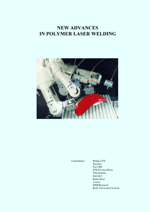
Some boundary conditions as to materials and product design have to be fulfilled. The most important condition to the materials is that one product part should be transparent for laser radiation, whereas the other part has to be absorbent. As regards product design, the most important aspect is the geometry of the weld region. A large number of shapes can be used to obtain an optimum welding result. This publication describes the potential of polymer laser welding and presents information on product design, materials, process parameters and equipment. Attention is also given to the latest developments in the area of diode-lasers. This new type of laser is particularly attractive because of its interesting price/performance ratio. Their optical beam quality is somewhat less compared to conventional laser systems, but this is usually no disadvantage at all in case of polymer welding. Finally, the usage of the process is illustrated by means of a number of (potential) applications. These involve varying industrial areas. Product sizes range from the very small to the very large: - Miniature components for optical information storage - Miniature products for biomedical applications - Encapsulation of electronic components - Housings of personal electronic products - Automotive components - Double-walled window systems.
TPS(奥地利福尼斯)焊机使用说明书
电击是非常严重的危害,触电会对人的生命构 成威胁。 强电流产生的磁场,将会削弱重要电子设备的 功 能( 例 如 :心 脏 起 博 器 )。因 此 使 用 心 脏 起 博 器的人去工作间前必须先征得医生的同意。 保证所有焊接连线都连接紧密、完好无损并且 绝对绝缘,立即替换所有松动的接头和烧焦的 电缆。 主电源线路和枝干线路必须定期由有资历的电 工检测,以确保半导体元件正常运行。 在折开焊机之前,要绝对保证焊机断电,并对 带电元件放电。 如果必须在通电情况下完成工作,则必须有第 二个人在现场,以保证紧急情况时切断焊机的 电源。
图 1 TS4000/5000,TPS4000/5000 和 TP2700 焊机
控制面板(Standard). 控制面板(Comfort)
“方法”参数 ……………………………42
普通/脉冲 MIG/MAG 焊 TIG 焊
2
手工电弧焊
参数“模式”-----------------------------------43
专为机器人设计的特殊 2 步模式 焊铝的特殊特殊四步 模式 1(点焊)
概述 正确地运用设备 所有者/操作者的责任 人为的责任 安全操作及保护 防止焊接烟尘的危害 防止 飞溅引起的危害 防止网路电压和焊接电流伤害 注意事项 一般性的安全防范措施 安装焊机的安全措施 焊接电流不稳定的防范措施 焊机正常工作安全防范措施 安全检测 改装焊机 备用和损耗件 焊机检修 CE 标记 版权声明
安全操作及保护
为了您和他人的安全,须遵守以下注意事项: 在潮湿的条件下采取绝缘措施,如穿绝缘鞋
焊接时带绝缘手套。 带焊接面罩来保护眼睛免受紫外线的伤害。 穿上劳保工作服。 在噪音大的地方,采取一定的保护措施。 焊接时,如其他人在附近,你必须: 告知他们危险。 向他们提供保护装置或其它措施。 竖立保护隔离物或拉上防护帘。
英文焊接手册Welding handbook

Document provided by IHS Licensee=Shell Services International B.V./5924979112, 08/26/2004 23:33:59 MDT Questions or comments about this message: please call 1the Document Policy Group at 303-397-2295.2NOTE:Although care was taken in choosing and presenting the data in this guide, AWS cannot guarantee that it iserror free. Further, this guide is not intended to be an exhaustive treatment of the topic and therefore may not include all available information, including with respect to safety and health issues. By publishing this guide, AWS does not insure anyone using the information it contains against any liability or injury to property or persons arising from that use.© 2004 by American Welding Society. All rights reserved.Printed in the United States of AmericaCopyright American Welding Society Provided by IHS under license with AWSDocument provided by IHS Licensee=Shell Services International B.V./5924979112,08/26/2004 23:33:59 MDT Questions or comments about this message: please call the Document Policy Group at 303-397-2295.--`````,`,,``,`,,```,,,`,``-`-`,,`,,`,`,,`---The inspection requirements for the fabrication and welding of steel structures are very extensive. This PocketHandbook has been developed to provide a useful tool for inspectors to carry in their pockets or tool kits so that selected pertinent portions of the AWS Structural Welding Code—Steel, D1.1/D1.1M:2004, can be easilyreferenced at the job site. Underlining is as shown in the code.This publication is not to be considered as a substitute for the D1.1 code book. Rather, the Handbook is providedas a supplemental aid for the “deckplate” inspector. Only the complete code should be considered as the officialdocument to ensure that all of the quality attributes required for structural fabrication are performed correctly and completely.To assist the inspector, or other user, in verifying conformance to D1.1, the paragraph references, the table num-bers, and the figure numbers contained in this book are directly from the D1.1/D1.1M:2004 code. In addition, page numbering in this handbook is cross-referenced to reflect both the current page and the corresponding page from the D1.1/D1.1M:2004 code, separated by a “/.” This will provide an easy cross reference for the user to ensure that the complete requirements are understood when questions develop during the course of any inspection.IntroductionCopyright American Welding Society Provided by IHS under license with AWSDocument provided by IHS Licensee=Shell Services International B.V./5924979112, 08/26/2004 23:33:59 MDT Questions or comments about this message: please call the Document Policy Group at 303-397-2295.--`````,`,,``,`,,```,,,`,``-`-`,,`,,`,`,,`---3Requirements for Transitions Between Materials of Unequal Thickness (5)Thermal Cutting and Access Hole Requirements (9)Tolerance of Joint Dimensions (13)Dimensional Tolerances of Welded Structural Members (19)Base Material Surface Requirements (25)Weld Profile Requirements (26)Acceptance Criteria for Visual Inspection of Welds (32)Index (37)Table of ContentsCopyright American Welding Society Provided by IHS under license with AWSDocument provided by IHS Licensee=Shell Services International B.V./5924979112, 08/26/2004 23:33:59 MDT Questions or comments about this message: please call the Document Policy Group at 303-397-2295.--`````,`,,``,`,,```,,,`,``-`-`,,`,,`,`,,`---45Figure 2.21—Transition of Thickness of Butt Joints in Parts ofUnequal Thickness (Tubular) (see 2.25 [pg. 22])Requirements for Transitions Between Materials of Unequal Thickness5/pg. 55Copyright American Welding Society Provided by IHS under license with AWSDocument provided by IHS Licensee=Shell Services International B.V./5924979112, 08/26/2004 23:33:59 MDT Questions or comments about this message: please callthe Document Policy Group at 303-397-2295.-6Figure 2.21 (Cont’d)—Transition of Thickness of Butt Joints in Parts ofUnequal Thickness (Tubular) (see 2.25 [pg. 22])Requirements for Transitions Between Materials of Unequal Thickness6/pg. 55Copyright American Welding Society Provided by IHS under license with AWS Document provided by IHS Licensee=Shell Services International B.V./5924979112,08/26/2004 23:33:59 MDT Questions or comments about this message: please call the Document Policy Group at 303-397-2295.--7(see 2.7.1 [pg. 10] and 2.16.1.1 [pg. 14])Requirements for Transitions Between Materials of Unequal Thickness7/pg. 42Copyright American Welding Society Provided by IHS under license with AWSDocument provided by IHS Licensee=Shell Services International B.V./5924979112,08/26/2004 23:33:59 MDT Questions or comments about this message: please callthe Document Policy Group at 303-397-2295.--`````,`,,``,`,,```,,,`,``-`-`,,`,,`,`,,`---8Figure 2.12—Transition of Width (Cyclically Loaded Nontubular) (see 2.16.1.2 [pg. 14])Requirements for Transitions Between Materials of Unequal Thickness8/pg. 48Copyright American Welding Society Provided by IHS under license with AWSDocument provided by IHS Licensee=Shell Services International B.V./5924979112,08/26/2004 23:33:59 MDT Questions or comments about this message: please call the Document Policy Group at 303-397-2295.--`````,`,,95.15.4.3Roughness Requirements. In thermal cutting, the equipment shall be so adjusted and manipulated as to avoid cutting beyond (inside) the prescribed lines. The roughness of all thermal cut surfaces shall be no greater than that defined by the American National Standards Institute surface rough-ness value of 1000 µin. [25µm] for material up to 4in. [100 mm] thick and 2000µin. [50 µm] for mate-rial 4 in. to 8 in. [200 mm] thick, with the following exception: the ends of members not subject to calcu-lated stress at the ends shall not exceed a surface roughness value of 2000 µin. ANSI/ASME B46.1,Surface Texture (Surface Roughness, Waviness, and Lay) is the reference standard. AWS Surface Rough-ness Guide for Oxygen Cutting (AWS C4.1-77) may be used as a guide for evaluating surface roughness of these edges. For materials up to and including 4 in.[100 mm] thick, Sample No. 3 shall be used, and for materials over 4 in. up to 8 in. [200 mm] thick,Sample No. 2 shall be used. 5.15.4.4Gouge or Notch Limitations. Rough-ness exceeding these values and notches or gougesnot more than 3/16 in. [5 mm] deep on other wise satisfactory surfaces shall be removed by machining or grinding. Notches or gouges exceeding 3/16 in.[5mm] deep may be repaired by grinding if the nominal cross-sectional area is not reduced by more than 2%. Ground or machined surfaces shall be fared to the original surface with a slope not exceeding one in ten. Cut surfaces and adjacent edges shall be left free of slag. In thermal-cut surfaces, occasional notches or gouges may, with approval of the Engi-neer, be repaired by welding.5.16Reentrant CornersReentrant corners of cut material shall be formed to provide a gradual transition with a radius of not less than 1 in. [25 mm]. Adjacent surfaces shall meet without offset or cutting past the point of tangency.Thermal Cutting and Access Hole Requirements9/pg. 185Copyright American Welding SocietyProvided by IHS under license with AWSDocument provided by IHS Licensee=Shell Services International B.V./5924979112,08/26/2004 23:33:59 MDT Questions or comments about this message: please callthe Document Policy Group at 303-397-2295.--`````,`,,``,`,,```,,,`,``-`-`,,`,,`,`,,`---10The reentrant corners may be formed by thermal cut-ting, followed by grinding, if necessary, to meet the surface requirements of 5.15.4.3.5.17Beam Copes and Weld AccessHolesRadii of beam copes and weld access holes shall provide a smooth transition free of notches or cutting past the points of tangency between adjacent surfaces and shall meet the surface requirements of 5.15.4.3.5.17.1Weld Access Hole Dimensions. All weld ac-cess holes required to facilitate welding operations shall have a length (A ) from the toe of the weld preparation not less than 1-1/2 times the thickness of the material in which the hole is made. The height (h)of the access hole shall be adequate for depo-sition of sound weld metal in the adjacent plates and provide clearance for weld tabs for the weld in thematerial in which the hole is made, but not less than the thickness of the material. In hot rolled shapes and built-up shapes, all beam copes and weld access holes shall be shaped free of notches or sharp re-entrant corners except that when fillet web-to-flange welds are used in built-up shapes, access holes may terminate perpendicular to the flange. Fillet welds shall not be returned through weld access holes (see Figure 5.2).5.17.2Group 4 and 5 Shapes. For ASTM A6Group 4 and 5 shapes and built-up shapes with web material thickness greater than 1-1/2 in. [40 mm], the thermally cut surfaces of beam copes and weld access holes shall be ground to bright metal and inspected by either MT or PT. If the curved transition portion of weld access holes and beam copes are formed by pre-drilled or sawed holes, that portion of the access hole or cope need not be ground. Weld access holes and beam copes in other shapes need not be ground nor inspected by MT or PT.10/pg. 185Copyright American Welding Society Provided by IHS under license with AWSDocument provided by IHS Licensee=Shell Services International B.V./5924979112, 08/26/2004 23:33:59 MDT Questions or comments about this message: please call the Document Policy Group at 303-397-2295.--`````,`,,``,`,,```,,,`,``-`-`,,`,,`,`,,`---11Figure 5.2—Weld Access Hole Geometry (see 5.17.1 [pg. 185])11/pg. 196Copyright American Welding Society Provided by IHS under license with AWS Document provided by IHS Licensee=Shell Services International B.V./5924979112, 08/26/2004 23:33:59 MDT Questions or comments about this message: please callthe Document Policy Group at 303-397-2295.--`````,`,,``,`,,```,,,`,``-`-`,,`,,`,`,,`---12General Notes:For ASTM A 6 Group 4 and 5 shapes and welded built-up shapes with web thickness more than 1-1/2 in. [40 mm], preheat to 150°F [65°C] prior to thermal cutting, grind and inspect thermally cut edges of access hole using MT or PT methods prior to making web and flange splice groove welds.These are typical details for joints welded from one side against steel backing. Alternative joint designs should be considered.Notes:1.Radius shall provide smooth notch-free transition; R ≥ 3/8 in. [10 mm] (Typical 1/2 in. [12 mm]).2.Access hole made after welding web to flange.3.Access hole made before welding web to flange. Weld not returned through hole.4.h min = 3/4 in. [20 mm] or t w (web thickness), whichever is greater.Figure 5.2 (Cont’d)—Weld Access Hole Geometry (see 5.17.1 [pg. 185])12/pg. 196Copyright American Welding Society Provided by IHS under license with AWSDocument provided by IHS Licensee=Shell Services International B.V./5924979112,08/26/2004 23:33:59 MDT Questions or comments about this message: please call the Document Policy Group at 303-397-2295.--`````,`,,``,`,,```,,,`,``-`-`,,`,,`,`,,`---135.22.1Fillet Weld Assembly. The parts to be joined by fillet welds shall be brought into as close contact as practicable. The root opening shall not exceed 3/16in.[5mm] except in cases involving either shapes or plates 3 in. [75 mm] or greater in thickness if, after straightening and in assembly, the root opening cannot be closed sufficiently to meet this tolerance. In such cases, a maximum root opening of 5/16 in. [8 mm]may be used, provided suitable backing is used. Back-materials, or welds using a low-hydrogen process compatible with the filler metal deposited. If the sepa-ration is greater than 1/16 in. [2 mm], the leg of the fillet weld shall be increased by the amount of the root opening, or the contractor shall demonstrate that the required effective throat has been obtained.5.22.1.1Faying Surface. The separation be-tween faying surfaces of plug and slot welds, andof butt joints landing on a backing, shall not exceed 1/16 in. [2 mm]. Where irregularities in rolled shapes occur after straightening do not allow contact within the above limits, the procedure necessary to bring the material within these limits shall be subject to the approval of the Engineer. The use of filler plates shall be prohibited except as specified on the drawings or as specially approved by the Engineer and made in accordance with 2.13.5.22.2PJP Groove Weld Assembly. The parts to be joined by PJP groove welds parallel to the length of the member shall be brought into as close contact as practicable. The root opening between parts shall not exceed 3/16 in. [5 mm] except in cases involving rolled shapes or plates 3 in. [75 mm] or greater in thickness if, after straightening and in assembly, the root opening cannot be closed sufficiently to meet this tolerance. In such cases, a maximum root opening of 5/16 in. [8 mm] may be used, provided suitable back-ing is used and the final weld meets the requirements Tolerance of Joint Dimensions13/pg. 187Copyright American Welding Society Provided by IHS under license with AWSDocument provided by IHS Licensee=Shell Services International B.V./5924979112, 08/26/2004 23:33:59 MDT Questions or comments about this message: please call the Document Policy Group at 303-397-2295.--`````,`,,``,`,,```,,,`,``-`-`,,`,,`,`,,`---14for weld size. Tolerances for bearing joints shall be in conformance with the applicable contract specifications.5.22.3Butt Joint Alignment. Parts to be joined at butt joints shall be carefully aligned. Where the parts are effectively restrained against bending due to eccentricity in alignment, the offset from the theoreti-cal alignment shall not exceed 10% of the thickness of the thinner part joined, or 1/8 in. [3 mm], which-ever is smaller. In correcting misalignment in such cases, the parts shall not be drawn in to a greater slope than 1/2 in. [12 mm] in 12 in. [300 mm]. Mea-surement of offset shall be based upon the centerline of parts unless otherwise shown on the drawings.5.22.3.1Girth Weld Alignment (Tubular).Abutting parts to be joined by girth welds shall be carefully aligned. No two girth welds shall be located closer than one pipe diameter or 3 ft [1 m], whichever is less. There shall be no more than two girth welds in any 10 ft [3 m] interval of pipe, except as may be agreed upon by the Owner and Contractor. Radial offset of abutting edges of girth seams shall not exceed 0.2t (where t is the thickness of the thinner member) and the maximum allowable shall be 1/4 in.[6 mm], provided that any offset exceeding 1/8 in.[3mm] is welded from both sides. However, with the approval of the Engineer, one localized area per girth seam may be offset up to 0.3t with a maximum of 3/8 in. [10 mm], provided the localized area is under 8t in length. Filler metal shall be added to this region to provide a 4 to 1 transition and may be added in conjunction with making the weld. Offsets in excess of this shall be corrected as provided in 5.22.3.Longitudinal weld seams of adjoining sections shall be staggered a minimum of 90°, unless closer spacing is agreed upon by the Owner and Fabricator.5.22.4Groove Dimensions5.22.4.1Nontubular Cross-Sectional Variations.With the exclusion of ESW and EGW, and with the exception of 5.22.4.3 for root openings in excess of those permitted in Figure 5.3, the dimensions of the cross section of the groove welded joints which vary from those shown on the detail drawings by more than these tolerances shall be referred to the Engineer for approval or correction.14/pg. 187Copyright American Welding SocietyProvided by IHS under license with AWSDocument provided by IHS Licensee=Shell Services International B.V./5924979112,08/26/2004 23:33:59 MDT Questions or comments about this message: please call the Document Policy Group at 303-397-2295.--`````,`,,``,`,,```,,,`,``-`-`,,`,,`,`,,`---155.22.4.2Tubular Cross-Sectional Variations.Variation in cross section dimension of groove welded joints, from those shown on the detailed drawings,shall be in accordance with 5.22.4.1 except:(1)Tolerances for T-, Y-, and K-connections are included in the ranges given in 3.13.4.(2)The tolerances shown in Table 5.5 apply to CJP tubular groove welds in butt joints, made from one side only, without backing.5.22.4.3Correction. Root openings greater than those permitted in 5.22.4.1, but not greater than twice the thickness of the thinner part or 3/4 in. [20 mm],whichever is less, may be corrected by welding to acceptable dimensions prior to joining the parts by welding.5.22.4.4Engineer’s Approval. Root openings greater than allowed by 5.22.4.3 may be corrected by welding only with the approval of the Engineer.5.22.5Gouged Grooves. Grooves produced by gouging shall be in substantial conformance with groove profile dimensions as specified in Figure 3.3and 3.4 and provisions of 3.12.3 and 3.13.1. Suitable access to the root shall be maintained.15/pgs. 187–188Copyright American Welding Society Provided by IHS under license with AWSDocument provided by IHS Licensee=Shell Services International B.V./5924979112, 08/26/2004 23:33:59 MDT Questions or comments about this message: please call the Document Policy Group at 303-397-2295.--`````,`,,``,`,,```,,,`,``-`-`,,`,,`,`,,`---16Figure 5.3—Workmanship Tolerances in Assembly of Groove Welded Joints (see 5.22.4.1 [pg. 187])16/pg. 197Copyright American Welding Society Provided by IHS under license with AWSDocument provided by IHS Licensee=Shell Services International B.V./5924979112,08/26/2004 23:33:59 MDT Questions or comments about this message: please call the Document Policy Group at 303-397-2295.--`````,`,,``,`,,```,,,`,``-`-`,,`,,`,`,,`---17Root Not BackgougedRoot Backgouged in.mm in.mm(1)Root face of joint ±1/162Not limited (2)Root opening ofjoints without backing±1/162+1/16–1/8023Root opening of joints with backing +1/40–1/1662Not applicable (3)Groove angle ofjoint+10°–5°0+10°–5°0General Note: See 5.22.4.2 for tolerances for CJP tubular groove welds made from one side without backing.Figure 5.3 (Cont’d)—Workmanship Tolerances in Assembly of Groove Welded Joints (see 5.22.4.1 [pg. 187])17/pg. 197Copyright American Welding Society Provided by IHS under license with AWSDocument provided by IHS Licensee=Shell Services International B.V./5924979112, 08/26/2004 23:33:59 MDT Questions or comments about this message: please call the Document Policy Group at 303-397-2295.18Table 5.5Tubular Root Opening Tolerances (see 5.22.4.2 [pg. 187])Root Face of Joint Root Opening of Joints without Steel Backing Groove Angle of Jointin.mm in.mm deg SMAW GMAW FCAW±1/16±1/32±1/16±2±1±2±1/16±1/16±1/16±2±2±2±5±5±5General Note: Root openings wider than allowed by the above tolerances, but not greater than the thickness of the thinner part,may be built up by welding to acceptable dimensions prior to the joining of the parts by welding.18/pg. 194Copyright American Welding Society Provided by IHS under license with AWSDocument provided by IHS Licensee=Shell Services International B.V./5924979112,08/26/2004 23:33:59 MDT Questions or comments about this message: please call the Document Policy Group at 303-397-2295.--`````,`,,``,`,,```,,,`,``-`-`,,`,,`,`,,`---5.23Dimensional Tolerances of WeldedStructural MembersThe dimensions of welded structural members shall conform to the tolerances of (1) the general specifications governing the work, and (2) the special dimensional tolerances in 5.23.1 to 5.23.11.3. (Note that a tubular column is interpreted as a compression tubular member.)5.23.1Straightness of Columns and Trusses. For welded columns and primary truss members, regard-less of cross section, the maximum variation in straightness shall beLengths of less than 30 ft [9 m]:1 mm × No. of meters of total lengthLengths of 30 ft [10 m] to 45 ft [14 m] = 3/8 in. [10 mm]Lengths over 45 ft [15 m]:5.23.2Beam and Girder Straightness (No Cam-ber Specified). For welded beams or girders, regard-less of cross section, where there is no specifiedcamber, the maximum variation in straightness shallbe1 mm × No. of meters of total length5.23.3Beam and Girder Camber (TypicalGirder). For welded beams or girders, other than those whose top flange is embedded in concrete with-out a designed concrete haunch, regardless of cross1/8 in.No. of ft of total length10-------------------------------------------------------×3/8 in. + 1/8 in.No. of ft of total length – 4510--------------------------------------------------------------------×10 mm + 3 mmNo. of meters of total length – 153-------------------------------------------------------------------------------×1/8 in.No. of ft of total length10-------------------------------------------------------×Dimensional Tolerances of Welded Structural Members19/pg. 188Copyright American Welding Society Provided by IHS under license with AWSDocument provided by IHS Licensee=Shell Services International B.V./5924979112,08/26/2004 23:33:59 MDT Questions or comments about this message: please callthe Document Policy Group at 303-397-2295.--`````,`,,``,`,,```,,,`,``-`-`,,`,,`,`,,`---1920section, the maximum variation from required cam-ber at shop assembly (for drilling holes for field splices or preparing field welded splices) shall be at midspan,–0, +1-1/2 in. [40mm] for spans ≥100ft[30 m]–0, +3/4 in. [20 mm] for spans < 100 ft [30 m]at supports,0 for end supports± 1/8 [3 mm] for interior supports at intermediate points, –0, + wherea =distance in feet [meters] from inspectionpoint to nearest support S =span length in feet [meters]b =1-1/2 in. [40 mm] for spans ≥ 100 ft [30 m]b =3/4 in. [20 mm] for spans < 100 ft [30 m]See Table 5.6 for tabulated values.5.23.4Beam and Girder Camber (without Designed Concrete Haunch). For members whose top flange is embedded in concrete without adesigned concrete haunch, the maximum variation from required camber at shop assembly (for drilling holes for field splices or preparing field welded splices) shall beat midspan,± 3/4 in. [20 mm] for spans ≥ 100 ft[30 m]± 3/8 in. [10 mm] for spans < 100 ft [30 m]at supports,0 for end supports± 1/8 in. [3 mm] for interior supports at intermediate points, ± where a and S are as defined aboveb =3/4 in. [20 mm] for spans ≥ 100 ft [30 m]b =3/8 in. [10 mm] for spans < 100 ft [30 m]See Table 5.7 for tabulated values.Regardless of how the camber is shown on the detail drawings, the sign convention for the allowable vari-ation is plus (+) above, and minus (–) below, the 4(a)b(1 – a/S)S --------------------------------4(a)b(1 – a/S)S--------------------------------20/pgs. 188–189Copyright American Welding SocietyProvided by IHS under license with AWSDocument provided by IHS Licensee=Shell Services International B.V./5924979112,08/26/2004 23:33:59 MDT Questions or comments about this message: please call the Document Policy Group at 303-397-2295.--`````,`,,``,`,,```,,,`,``-`-`,,`,,`,`,,`---21Table 5.6Camber Tolerance for Typical Girder (see 5.23.3 [pg. 188–189])Camber Tolerance (in inches)a/SSpan 0.10.20.30.40.5≥ 100 ft 9/1611-1/41-7/161-1/2< 100 ft1/41/25/83/43/4Camber Tolerance (in millimeters)a/SSpan 0.10.20.30.40.5≥ 30m 1425343840< 30 m713171920Table 5.7Camber Tolerance for Girderswithout a Designed Concrete Haunch(see 5.23.4 [pg. 188–189])Camber Tolerance (in inches)a/SSpan 0.10.20.30.40.5≥ 100 ft 1/41/25/83/43/4< 100 ft1/81/45/163/83/8Camber Tolerance (in millimeters)a/SSpan 0.10.20.30.40.5≥ 30 m713171920< 30 m468101021/pg. 194Copyright American Welding Society Provided by IHS under license with AWSDocument provided by IHS Licensee=Shell Services International B.V./5924979112, 08/26/2004 23:33:59 MDT Questions or comments about this message: please call the Document Policy Group at 303-397-2295.--`````,`,,``,`,,```,,,`,``-`-`,,`,,`,`,,`---22detailed camber shape. These provisions also apply to an individual member when no field splices or shop assembly is required. Camber measurements shall be made in the no-load condition.5.23.5Beam and Girder Sweep. The maximum variation in specified sweep at the midpoint shall be1 mm × No. of meters of total lengthprovided the member has sufficient lateral flexibility to permit the attachment of diaphragms, cross-frames, lateral bracing, etc., without damaging the structural member or its attachments.5.23.6Variation in Web Flatness5.23.6.1Measurements. Variations from flatness of girder webs shall be determined by measuring the offset from the actual web centerline to a straight edge whose length is greater than the least panel dimension and placed on a plane parallel to the nomi-nal web plane. Measurements shall be taken prior to erection (see Commentary).5.23.6.2Statically Loaded Nontubular Struc-tures. Variations from flatness of webs having a depth, D, and a thickness, t, in panels bounded by stiffeners or flanges, or both, whose least panel dimension is d shall not exceed the following:Intermediate stiffeners on both sides of webwhere D/t < 150, maximum variation = d/100where D/t ≥ 150, maximum variation = d/80Intermediate stiffeners on one side only of web where D/t < 100, maximum variation = d/100where D/t ≥ 100, maximum variation = d/67No intermediate stiffenerswhere D/t ≥ 100, maximum variation = D/150(See Annex VI for tabulation.)5.23.6.3 Cyclically Loaded Nontubular Struc-tures. Variation from flatness of webs having a depth, D, and a thickness, t, in panels bounded by stiffeners or flanges, or both, whose least panel dimension is d shall not exceed the following: 1/8 in.No. of feet of total length10------------------------------------------------------------×±22/pg. 189Copyright American Welding SocietyProvided by IHS under license with AWSDocument provided by IHS Licensee=Shell Services International B.V./5924979112,08/26/2004 23:33:59 MDT Questions or comments about this message: please call the Document Policy Group at 303-397-2295.--`````,`,,``,`,,```,,,`,``-`-`,,`,,`,`,,`---23Intermediate stiffeners on both sides of web Interior girders—where D/t < 150—maximum variation = d/115where D/t ≥ 150—maximum variation = d/92Fascia girders—where D/t < 150—maximum variation = d/130where D/t ≥ 150—maximum variation = d/105Intermediate stiffeners on one side only of web Interior girders—where D/t < 100—maximum variation = d/100where D/t ≥ 100—maximum variation = d/67Fascia girders—where D/t < 100—maximum variation = d/120where D/t ≥ 100—maximum variation = d/80No intermediate stiffeners—maximum variation = D/150(See Annex VII for tabulation.)5.23.6.4 Excessive Distortion. Web distortions of twice the allowable tolerances of 5.23.6.2 or 5.23.6.3shall be satisfactory when occurring at the end of a girder which has been drilled, or subpunched and reamed; either during assembly or to a template for afield bolted splice; provided, when the splice plates are bolted, the web assumes the proper dimensional tolerances.5.23.6.5Architectural Consideration. If archi-tectural considerations require tolerances more restrictive than described in 5.23.6.2 or 5.23.6.3, spe-cific reference must be included in the bid documents.5.23.7 Variation Between Web and Flange Center-lines. For built-up H or I members, the maximum variation between the centerline of the web and the centerline of the flange at contact surface is 1/4 in.[6mm].5.23.8Flange Warpage and Tilt. For welded beams or girders, the combined warpage and tilt of flange shall be determined by measuring the offset at the toe of the flange from a line normal to the plane of the web through the intersection of the centerline of the web with the outside surface of the flange plate. This offset shall not exceed 1% of the total flange width or 1/4 in. [6 mm], whichever is greater, except that 23/pg. 189Copyright American Welding SocietyProvided by IHS under license with AWSDocument provided by IHS Licensee=Shell Services International B.V./5924979112,08/26/2004 23:33:59 MDT Questions or comments about this message: please callthe Document Policy Group at 303-397-2295.--`````,`,,``,`,,```,,,`,``-`-`,,`,,`,`,,`---。
焊接手册

焊接工艺手册第一节焊接的原理一、焊接原理:1.焊锡目的(1)电的接续(使金属与金属相接合,从而形成良好的电的导通)(2)机器的接续(使金属与金属相接合,从而固定两者之间的位置,实现持久的机械连接。
)(3)密闭的效果(通过焊锡可防止没有焊锡的部位进入空气、油、水等杂质)(4)其它(根据金属表面的镀金,可防止氧化处理)2.焊接的原理焊锡借助于助焊剂的作用,经过加热熔化成液态,进入被焊金属的缝隙,在焊接物的表面,形成金属合金使两种金属体牢固地连接在一起,不过焊接并不是通过熔化的焊料将元气件的引脚与焊盘进行简单的粘合,而是焊料中的锡与铜发生了化学反应,形成的金属合金就是焊锡中锡铅的原子进入被焊金属的晶格中生成的一种新的物质,因锡铅两种金属原子的壳层相互扩散,依靠原子间的内聚力使两种金属永久地牢固结合在一起。
如下图是放大1000倍的焊点剖面,这使我们清楚的看到在焊盘与焊料之间确实形成了新的物质,经过研究证明这种新物质是由Cu3Sn和Cu5Sn6。
3.焊接的分类不加热超声波焊接加压焊(加热或不加热)加热到局部熔化接触焊对焊金属焊接手工烙铁焊(锡线)浸焊(锡条)锡焊(母材不熔化、焊料熔化)焊锡波峰焊(锡条)再流焊(锡膏)4.有关焊锡之名词(1)点焊:将导线或元件脚穿过线路板或其它焊锡孔位,单个焊接在铜片位上,一次只焊接一个焊点.(2)贴焊:将零件脚、导线或排梳、排线等表面焊接在线路板其它锡点面上,一次只焊接一个焊点。
(3)拖焊:将排梳或排线穿过线路板锁孔,沿排孔方向进行焊接,一次可焊接多个焊点。
(4)执锡:过锡炉后的机芯板,有少锡、短路等不户锡点,需将其修改成完好锡点,即机芯执锡。
5.焊接必须具备的条件(1)、焊件必须具有良好的可焊性(在焊接时,由于高温使金属表面产生氧化膜,影响材料的可焊性,为了提高可焊性,一般采用表面镀锡、镀铜等措施来防止表面的氧化)(2)、焊件表面必须保持清洁(即使可焊性良好的焊件,由于储存或被污染,都可能在焊件表面产生有害的氧化膜和油污)(3)、要使用合适的助焊剂(不同的焊接工艺,应选择不同的助焊剂)(4)、焊件要加热到适当的温度(不但焊锡要加热到熔化,而且应该同时将焊件加热到能够熔化焊锡的温度)二.焊接的主要方法1. 焊接顺序(1).将烙铁头在含水分的海绵上清理干净,准备焊接:左手拿锡丝,右手握烙铁,进入备焊状态。
焊接常见缺陷及处理书籍
焊接常见缺陷及处理书籍
以下是一些关于焊接常见缺陷及处理的书籍推荐:
1. "Welding Defects and Inspection" by R. S. Parmar
《焊接缺陷与检测》作者:R. S. Parmar
2. "Metallurgy of Welding" by H. K. D. H. Bhadeshia and R. W. K. Honeycombe
《焊接冶金学》作者:H. K. D. H. Bhadeshia和R. W. K. Honeycombe
3. "Welding Handbook, Volume 1: Fundamentals of Welding" by American Welding Society
《焊接手册,卷1:焊接基础》作者:美国焊接学会
4. "Welding Inspection Technology" by J. M. Biukovic
《焊接检测技术》作者:J. M. Biukovic
5. "Welding Metallurgy and Weldability" by John C. Lippold and Roger A. Buchanan
《焊接冶金学与可焊性》作者:John C. Lippold和Roger A. Buchanan
这些书籍将为您提供焊接缺陷和处理的详细知识,并介绍了如何进行焊接检测和质量控制。
请根据您的需求选择适合的书籍来进一步学习。
- 1、下载文档前请自行甄别文档内容的完整性,平台不提供额外的编辑、内容补充、找答案等附加服务。
- 2、"仅部分预览"的文档,不可在线预览部分如存在完整性等问题,可反馈申请退款(可完整预览的文档不适用该条件!)。
- 3、如文档侵犯您的权益,请联系客服反馈,我们会尽快为您处理(人工客服工作时间:9:00-18:30)。
焊接手册(第2版) 焊接方法及设备(第一卷)
本卷共分6篇、41章,特点是焊接工艺与设备兼顾,原理与工艺(或设备)密切联系。
目的是引导读者正确选择和使用焊接方法及设备,并提供解决焊接工艺问题的基本途径。
具体内容包括各种电弧焊、电阻焊、高能束焊、钎焊、焊接过程自动化技术以及其他焊接方法等。
增加了药芯汉斯电弧焊及SMT中的焊接技术两章。
【目录】
第1章焊接方法概述
第1篇电弧焊
第2章弧焊电源
第3章焊条电弧焊
第4章埋弧焊
第5章钨极气体保护焊
第6章等离子弧焊及切割
第7章熔化极气体保护焊
第8章药芯焊丝电弧焊
第9章水下电弧焊于切割
第10章螺柱焊
第11章碳弧气刨
第2篇电阻焊
第12章点焊
第13章缝焊
第14章凸焊
第15章对焊
第16章电阻焊设备
第17章电阻焊质量检验及监控
第3篇高能束焊
第18章电子束焊
第19章激光焊于切割
第4篇钎焊
第20章钎焊方法及工艺
第21章钎焊材料
第22章各种材料的钎焊
第5篇其他焊接方法
第23章电渣焊及电渣压力焊
第24章高频焊
第25章气焊气割及高压水射流切割
第26章气压焊
第27章热剂焊(铝热焊)
第28章爆炸焊
第29章摩擦焊
第30章变性焊
第31章超声波焊接
第32章扩散焊
第33章堆焊
第34章热喷涂
第35章SMT中的焊接技术
第36章胶接
第6篇焊接过程自动化技术
第37章焊接电弧控制技术
第38章焊接传感器及伺服装置
第39章计算机在焊接中的应用
第40章焊接机器人
第41章专用焊接设备设计概要
-------------------
焊接手册(第2版) 材料的焊接(第二卷)
本卷分5篇、23章。
内容包括:材料焊接性基础、铁与钢、有色金属、异种材料、新型材料的焊接。
按生产的需要提供母材性能及焊接特点、焊接材料、焊接工艺、缺欠及防止,特别强调给出并分析生产实例、使手册更为实用。
【目录】
第1篇材料的焊接性基础
第1章焊接热过程
第2章焊接冶金
第3章焊接热影响区组织转变及其性能变化
第4章焊接缺欠
第5章金属焊接性及其试验方法
第2篇铁与钢的焊接
第6章碳钢的焊接
第7章低合金钢的焊接
第8章耐热钢的焊接
第9章不锈钢的焊接
第10章其它高合金钢的焊接
第11章铸铁的焊接
第3篇有色金属的焊接
第12章铝、镁及其合金的焊接
第13章钛及其合金的焊接
第14章铜及铜合金的焊接
第15章高温合金的焊接
第16章镍基耐蚀合金的焊接
第17章难熔金属的焊接
第18章稀贵及其它有色金属的焊接
第4篇异种材料的焊接
第19章异种金属的焊接
第20章金属材料堆焊
第5篇新型材料的焊接
第21章塑料的焊接
第22章陶瓷与陶瓷陶瓷与金属的连接
第23章复合材料的焊接
--------------------
焊接手册(第2版) 焊接结构(第三卷)
本卷分为3篇、27章,介绍了焊接结构选材、设计、制造诸方面的问题,力求通过对典型结构的分析等介绍合理的焊接。
结构构造形式。
具体内容包括:焊接结构基础、原则与方法;机械零部件、压力容器、建筑结构、铁路车辆、船体、起重机、动力机械等焊接结构的设计、制造,以及焊接生产的机械化与自动化,生产中常用设备、焊接结构的无损检测,焊接车间设计,焊接生产组织与经济,安全与劳动保护。
【目录】
第1篇焊接结构基础
第1篇焊接结构基础
第1章常用焊接结构材料
第2章焊接接头及其设计
第3章焊接接头的力学性能
第4章焊接应力与变形
第5章焊接结构疲劳度
第6章焊接结构的断裂及安全评定
第7章焊接结构的环境效应
第8章标准与法规
第2篇典型结构设计
第9章焊接结构设计原则与方法
第10章焊接基本构件的设计与计算
第11章机械零部件焊接结构
第12章锅炉、压力容器与管道
第13章建筑焊接结构
第14章铁路机车车辆焊接结构
第15章船舶与海洋工程焊接结构
第16章起重机焊接结构
第17章动力机械焊接结构
第18章焊接钢桥
第19章工程机械焊接结构
第3篇焊接结构生产
第20章焊接结构制造工艺
第21章焊接结构生产用设备
第22章典型焊接结构的制造
第23章焊接结构生产的机械化和自动化第24章焊接结构生瓣质量管理及无损检测第25章焊接生产组织与经济
第26章焊接车间设计
第27章焊接安全与卫生防护。