建筑自力式流量平衡阀安装说明书
平衡阀安装使用完整版

平衡阀安装使用集团标准化办公室:[VV986T-J682P28-JP266L8-68PNN]平衡阀安装使用1、安装位置平衡阀可安装在供水管路上,也可安装在回水管路上(每个环路中只需安装一处)。
对于热力站的一次环路侧来说,为方便平衡调试,建议将平衡阀安装在水温较低的回水管路上。
总管上的平衡阀,宜安装在供水总管水泵后(水泵下游),以防止由于水泵前(阀门后)压力过低,可能发生水泵气蚀现象。
2、尽量安装在直管段上由于平衡阀具有流量计量功能,为使流经阀门前后水流稳定,保证测量精度,在条件允许的情况下应尽量将平衡阀安装在直管段处。
3、注意新系统与原有系统的平衡当安装有平衡阀的新系统连接于原有供热(冷)管网时,必须注意新系统与原有系统水量分配平衡问题,以免安装了平衡阀的新系统(或改造系统)的水阻力比原有系统高,而达不到应有的水流量。
如图5所示,(a)为新系统连接于原有系统的末端;(b)为新系统连接于原有系统的中间位置,应在原有系统的入口处加设平衡阀。
图5见附件4、不应随意变动平衡阀开度管网系统安装完毕,并具备测试条件后,使用专用智能仪表对全部平衡阀进行调试整定,并将各阀门开度锁定,使管网实现水力工况平衡。
在管网系统正常运行过程中,不应随意变动平衡阀的开度,特别是不应变动开度锁定装置。
5、不必再安装截止阀在检修某一环路时,可将该环路上的平衡阀关闭,此时平衡阀起到截止阀截断水流的作用,检修完毕后再回复到原来锁定的位置。
因此安装了平衡阀,就不必再安装截止阀。
6、系统增设(或取消)环路时应重新调试整定在管网系统中增设(或取消)环路时,除应增加(或关闭)相应的平衡阀之外,原则上所有新设的平衡阀及原有系统环路中的平衡阀均应重新调试整定(原环路中支管平衡阀不必重新调整)。
自力式流量控制阀安装说明
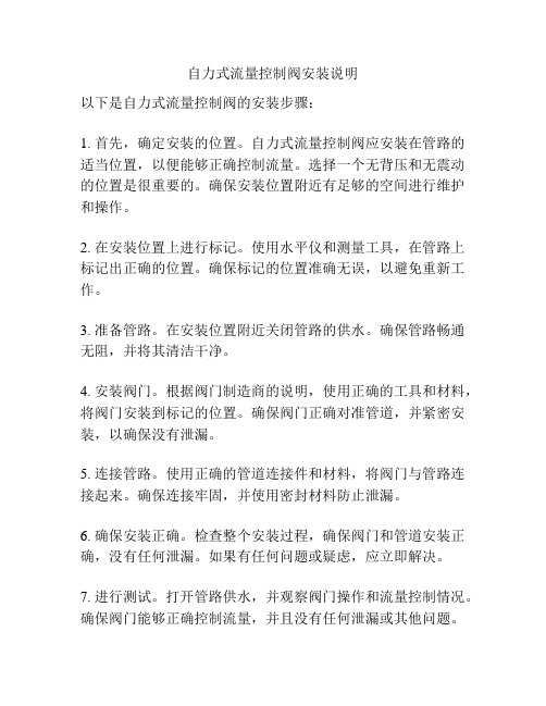
自力式流量控制阀安装说明以下是自力式流量控制阀的安装步骤:1. 首先,确定安装的位置。
自力式流量控制阀应安装在管路的适当位置,以便能够正确控制流量。
选择一个无背压和无震动的位置是很重要的。
确保安装位置附近有足够的空间进行维护和操作。
2. 在安装位置上进行标记。
使用水平仪和测量工具,在管路上标记出正确的位置。
确保标记的位置准确无误,以避免重新工作。
3. 准备管路。
在安装位置附近关闭管路的供水。
确保管路畅通无阻,并将其清洁干净。
4. 安装阀门。
根据阀门制造商的说明,使用正确的工具和材料,将阀门安装到标记的位置。
确保阀门正确对准管道,并紧密安装,以确保没有泄漏。
5. 连接管路。
使用正确的管道连接件和材料,将阀门与管路连接起来。
确保连接牢固,并使用密封材料防止泄漏。
6. 确保安装正确。
检查整个安装过程,确保阀门和管道安装正确,没有任何泄漏。
如果有任何问题或疑虑,应立即解决。
7. 进行测试。
打开管路供水,并观察阀门操作和流量控制情况。
确保阀门能够正确控制流量,并且没有任何泄漏或其他问题。
8. 进行维护。
定期检查阀门和管道的情况,确保其正常运行。
根据阀门制造商的说明执行必要的维护措施。
请注意,以上步骤仅为参考,具体的安装步骤可能因不同的阀门型号和厂家而有所不同。
因此,在安装之前,请务必查阅阀门制造商提供的具体安装说明,并按照其指示进行安装。
如果对安装过程有任何疑问或困惑,建议咨询专业人士或阀门制造商以获取更详细的指导。
自力式压力调节阀安装与维护
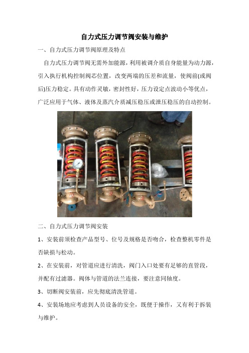
自力式压力调节阀安装与维护一、自力式压力调节阀原理及特点自力式压力调节阀无需外加能源,利用被调介质自身能量为动力源,引入执行机构控制阀芯位置,改变两端的压差和流量,使阀前(或阀后)压力稳定。
具有动作灵敏,密封性好,压力设定点波动小等优点,广泛应用于气体、液体及蒸汽介质减压稳压或泄压稳压的自动控制。
二、自力式压力调节阀安装1、安装前须检查产品型号、位号及规格是否吻合,检查整机零件是否缺损与松动。
2、在安装前,对管道应进行清洗,阀门入口处要有足够的直管段,并配有过滤器。
阀体与管道的法兰连接,要注意同轴度。
3、切断阀安装前,应先彻底清洗管道。
4、安装场地应考虑到人员设备的安全,既便于操作,又有利于拆装与维护。
5、阀门应正立垂直安装在水平管道上,不得已时可倾斜安装,尽量避免水平安装,阀自重量较大或有振动的场合,要用支撑架。
6、介质流动方向应与阀体上的箭头指向一致。
气源应干燥、无油。
阀门应在环境温度-20~55℃场所使用。
三、自力式压力调节阀维护1、清洗阀门:对清洗一般介质,只要用水洗净就可以。
但对清洗有害健康的介质,首先要了解其性质,再选用相应的清洗办法。
2、阀门的拆卸:将外露表面生锈的零件先除锈,但在除锈前,要保护好阀座、阀芯、阀杆与推杆等精密零件的加工表面。
拆装阀座时应使用工具。
3、阀座:密封面有较小的锈斑与磨损,可用机械加工的方法进行,如损坏严重必须换新。
但不管修理或更换后的硬密封面,都必须进行研磨。
4、阀杆:表面损坏,只能换新。
5、推杆、导向与密封表面的损坏:对反作用执行机构必须换新,而对正作用执行机构,可用适当的修理后使用。
6、压缩弹簧:如有裂纹等影响强度的缺陷,必须换新。
7、易损零件:填料、密封垫片与O型圈,每次检修时,全部换新。
阀芯、膜片必须检查是否有预示将来可能发生的裂纹、老化与腐蚀痕迹,根据检查结果,决定是否更换,但膜片使用期一般多2-3年。
8、阀门组装要注意对中,螺栓要在对角线上拧紧,滑动部分要加润滑油。
自力式压差控制阀和自力式流量平衡阀要点

自力式压差控制阀和自力式流量平衡阀在供热和空调系统中常出现冷热不均,部分用户室温不达标,主要原因是水力工况不平衡,即各个热用户的水流量分配不合理,解决这个问题只有靠平衡阀来完成。
供热系统在传统的供热体制下是一种平均分配的供热模式,这种供热模式一般采取定流量的质调节。
晋城市热网采取的就是这种供热模式,在这种供热模式指导下,在每个热用户的系统所有入口全部安装了自力式流量平衡阀,但在安装和使用中存在一些问题。
以河北同力自控阀门制造有限公司生产的自力式流量平衡阀和自力式压差控制阀为例,简要说明它的原理和应用。
1 自力式流量平衡阀1.1 工作原理当介质进入主阀时,进口压力为P1 ,手动节流阀的前后压力分别为P2 和P3 ,当节流阀开启到某一位置时,即人为确定了“定流量”,以及相对应的固定值(P2-P 3),当系统流量增大时,(P2-P3 )的实际值超过了允许的给定值,此时,主阀、阀芯自动关小,直至流量重新维持到设定流量,反之亦然。
1.2 缺点产品一般要求最小工作压差为20kPa 。
如果安装在最不利回路上,势必要求循环泵多增加2m 水拄的工作扬程。
晋城市普便安装自力式流量平衡阀的做法是错误的,应采取离换热站(或直供低温水的锅炉房)近的楼安装,如果用户离换热站距离大于供热半径的80% 时就不宜安装这种自力式流量平衡阀。
1.3 安装位置热网近端流量过大,远端流量过小,近端资用压头大于用户需压头,必须用阀门消耗富余压头,即阀门压头= 富余压头= 资用压头-需用压头。
图1(a)为热用户平衡阀门安装位置及各压力点,如果用户供水管安装平衡阀调网,则P3 近似等于P4,P2 压力线见图1(b ),近乎平行P4。
如果用户回水管安装平衡阀凋网,则P2 近似等于P1,P3 压力线近乎平行P1。
户内实际供水压力为P2,回水压力为P3,如果压力过低会倒空,压力过高会导致铸铁暖汽片超压。
因此,晋城市平衡阀全部装于回水管的做法是错误的。
自力式压力调节阀安全操作规程
自力式压力调节阀安全操作规程引言自力式压力调节阀(以下简称PRV)是一种常用的工业设备,用于调节气体或液体管道中的压力。
在正常情况下,它可以提供稳定、安全的工作条件,但如果不正确使用或维护,就会导致安全事故的发生。
为了确保PRV的安全运行,制定本规程,提示PRV的安全操作方法和注意事项。
操作准备在操作PRV之前,需要做好以下准备工作:1.了解PRV的工作原理和性能参数,确保选择合适的PRV,并按照要求安装。
2.了解管道系统的结构和性能参数,确定PRV的安装位置和调节参数。
3.检查PRV安装的现场环境,确认无渗漏、无损坏、无阻塞等情况。
4.根据PRV的安装位置和管道系统的特点,准备好相应的安全防护设施,以防操作或维护时发生事故。
操作步骤1. PRV的调节和设定1.检查PRV的初始状态,确定其调节范围、稳定性和故障指示器是否正常。
2.根据需要,进行调节和设定。
一般情况下,不能随意改变PRV的设置。
如果需要更改,必须经过责任人同意,并做好相应的记录,以备查阅。
2. PRV的手动测试在以下情况下,需要进行PRV的手动测试:1.PRV长期未使用或维护。
2.PRV在运行中出现问题,需要进行故障排除。
3.PRV更换或维修后,需要测试其稳定性和精度。
手动测试的步骤如下:1.在安全区域内,操作人员佩戴好相应的防护设施,关闭所有与PRV相关的设备。
2.手动调整PRV的调节参数,并观察其各项指标的变化,确保调节范围、稳定性和故障指示器正常。
3.手动模拟管道中产生压力峰值,比如关闭某个阀门,留意PRV的反应情况,确保其能够稳定调节、及时响应。
4.操作完成后,恢复PRV的原有设置,将所有与PRV有关的设备重新启动。
3. PRV的日常维护1.定期检查PRV的状态和性能,反应灵敏性、流量等参数是否正常,及时处理故障,避免损坏和安全事故。
2.每周或每月定时清洗PRV,并进行内部检查,确保其处于良好的状态。
3.检查周围环境,确保不会干扰到PRV的工作,例如是否有气体、液体或杂物。
平衡阀安装方法

平衡阀安装方法专家观点:中国现代国际关系研究院世界经济研究所所长陈凤英:经济走强助推人民币汇率上调一、使用范围:本阀门是一种本平衡阀,适用于各种液体管路系统,是一种较为理想的新型节能阀门。
该阀设有刻度的数字显示,可直观调到任一位置,并可锁定。
工洲牌WM105型动态流量平衡阀主要应用于工业和民用建筑采暖管路系统。
目前在一些管纲系统中存在着水力失调问题,平衡阀提供了解决这一问题的手段,用它可以准确的调节压降和流量,用以改善管纲系统中液体流动状况,达到管纲液体平衡和节约能源的目的。
在双管纲工程改造中,应用此阀门仍可节约能源,得到较好效果。
二、使用范围:型号SP15-SP45F-10 备注试验压力 1.5MPa(15kgf/cm2)工作压力1MPa(10≤℃kgf/cm2)工作温度≤120℃适用介质水、油和其他液体特性曲线等百分比安装使用范围管纲系统的主干、分支干、室内供水干管、分支立管以及多台锅炉三、工洲牌SP45平衡阀性能参数:D D D1 D N-d h L H 重量KGN 250 141190 4-14 16231951065 1613114-14 1627221380 19151284-18 1831231810 0 21171484-18 1835262312 5 24201788-18 184293415 0 2652252028-18 1848334020 0 32282548-18 22533425 0 37533530912-182462230 0 4439536312-2224698四、工洲牌SP15内螺纹数字锁定平衡阀尺寸参数:D N ZGL S H 重量KG1 5 1/2”931112 0 3/4”11536121.52 5 1”125461251.83 2 5/14451324”0 040 3/2” 160 601402.5曲线图左图为在种阀门的流量特性曲线,本厂生产的是其中等百分比特性阀门。
自力式压差平衡阀常见的安装问题 (1)

自力式压差平衡阀常见的安装问题
随着热计量政策的推进,越来越多的小区陆续开始关注热网的水力平衡了,自力式压差平衡阀做为一种常见的水力平衡元件,自然市场需求量大增。
但要把自力式压差平衡阀用好,正确选型、正确安装和正确调试确一不可。
自力式压差平衡阀属于仪表阀的一种,不像开关阀那样容易安装,稍不留心就可能会影响其控制压差的效果。
从现场来看,常见的不正确安装有:
1、调节阀安装方向,朝上或者侧90度内为正确的安装方向。
这是因为调节阀的上端会设有排气孔,如果方向朝下,则排气孔完全失效,影响供热初期的调试;
2、自力式压差平衡阀用在供水管和回水管的型号是有差别的,一般来说不能互用,除非供回水的引压管都是取自工艺管,而非阀本体,则阀通用;
3、引压管安装时从管道中心线的水平侧取压,切勿放在管道的上端或者下端;上端安装可能导致管道非满管流时取压不准,下端安装可能引起压压管被污垢堵塞;
4、引压管的走向,引压管从工艺管道引出来时,请先朝下弯曲,再朝上走,否则可能引起引压管积气,影响压力的传输;
5、压差平衡阀要控制的是用户两端(或者单元间)的压差恒定,因此其压力测点必须取于用户的两端,否则不起作用。
如果压差阀装在供水管上,则+端压差取自阀后,-端压差取自回水管;如果压差阀装在回水管上,则+端压差取自供水管,-端压差取自阀前。
上图中的压差平衡阀装在回水管上,而回水管的取压取在了阀后,正确的位置应该取在阀前。
正确的压差平衡阀安装步骤应该如下:
请安装时一定要注意阀的流向,取压点的位置,排气管以及压差调定点调整。
CIa-VaI Model 100-01 Hytrol Ваle 自动平衡阀说明书
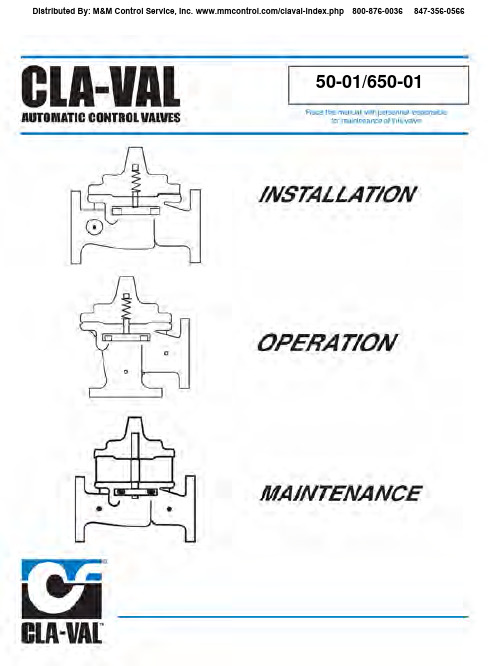
50-01/650-01installation with the cover UP is advisable. This makes internal parts readily accessible for periodic inspection.6. Caution must be taken in the installation of this valve to insure that galvanic and/or electrolytic action does not take place. The proper use of dielectric fittings and gaskets are required in all 100-01INSTALLATION / OPERATION / MAINTENANCE2458" - 24" SEAT DETAIL 1 1/4" - 6" SEAT DETAIL 16" COVER DETAILItem Description 1.Pipe Plug2.Drive Screws (for nameplate)3.Hex Nut (8” and larger)4.Stud (8” and larger)5.Cover Bearing6.Cover7.Stem Nut8.Diaphragm Washer 9.Diaphragm10.Spacer Washers 11.Disc Guide 12.Disc Retainer 13.Disc 14.Stem 15.Seat 16.Body 17.Spring22.Flat Head Screws (8” and larger)23.Seat O-Ring24.Hex head Bolt (1 1/4” thru 4”)plate26.Upper Spring Washer (Epoxy coated valves only)27.Lower Spring Washer (Epoxy coated valves only)28.Cover Bearing Housing (16” only)29.Cover O-Ring (16’” only)30.Hex Bolt (16” only)31.Pipe Cap (16” only)PARTS LIST6100-01I N S T A L L A T I O N / O P E R A T I O N / M A I N T E N A N C Ef o r e d ,g m n l y l o n s c ,i s c i e d l e d i n gN-100-01 (R-5/09)1. Tightens bolts/nuts in a “Star” or “Cross-Over” pattern following the numbers shown above to insure that cover seats evenly on the diaphragm material and body.2. Torque the bolt/nuts in three stages with a "Star" or "Cross-Over" pattern for each stage:A. To approximately 10% of final torque.B. To approximately 75% of final torque.C. To final required torque.3. Valves that are to be tested to 375 PSI or higher should be retorqued after 24 hours.600 Series Hytrol Valve100-20INSTALLATION / OPERATION / MAINTENANCE(Reduced Internal Port)When ordering parts,please specify:• All nameplate data • Item Number • DescriptionStrainer and Needle Valve AssemblyX42N-2PL- X42N-2 (R-4/09)PARTS LISTDESCRIPTIONThe CRL Pressure Relief Control is a direct acting, spring loaded, diaphragm type relief valve. It may be used as a self-contained valve or as a pilot control for a Cla-Val Main valve. It opens and closes within very close pressure limits.INSTALLATIONThe CRL Pressure Relief Control may be installed in any position. The control body (7) has one inlet and one outlet port with a side pipe plug (24) at each port. These plugs are used for control connections or gauge applications. The inlet in the power unit body (6) is the sensing line port.A flow arrow is marked on the body casting.OPERATIONThe CRL Pressure Relief Control is normally held closed by the force of the compression spring above the diaphragm; control pressure is applied under the diaphragm.When the controlling pressure exceeds the spring setting, the disc is lifted off its seat, permitting flow through the control.When controlling pressure drops below spring setting, the spring returns the control to its normally closed position.ADJUSTMENT PROCEDUREThe CRL Pressure Relief Control can be adjusted to provide a relief set-ting at any point within the range found on the nameplate.Pressure adjustment is made by turning the adjustment screw (9) to vary the spring pressure on the diaphragm. Turning the adjustment screw clockwise increases the pressure required to open the valve. Counterclockwise decreases the pressure required to open the valve. When pressure adjustments are complete the jam nut (10) should be tightened and the protective cap (1) replaced. If there is a problem of tampering, lock wire holes have been provided in cap and cover. Wire the cap to cover and secure with lead seal.DISASSEMBLYThe CRL Pressure Relief Control does not need to be removed from the line for disassembly. Make sure that pressure shut down is accompanied prior to disassembly. If the CRL is removed from the line for disassembly be sure to use a soft jawed vise to hold body during work.Refer to Parts List Drawing for Item Numbers.1.Remove cap (1), loosen jam nut (10) and turn adjustingscrew counterclockwise until spring tension is relieved.2.Remove the eight screws (4) holding the cover (3) andpowerunit body (6). Hold the cover and powerunit togetherand place on a suitable work surface.See NOTE under REASSEMBLY.3.Remove the cover (3) from powerunit body (6). The spring(12) and two spring guides (11).4.Remove nut (13) from stem (19) and slide off the belleville washer(14), the upper diaphragm washer (15) and the diaphragm (16).5.Pull the stem (19) with the disc retainer assembly (21) through thebottom of powerunit. The lower diaphragm washer (17) will slide off of stem top.6.Remove jam nut (23) and disc retainer assembly (21) from stem.Use soft jawed pliers or vise to hold stem. The polished surface of stem must not be scored or scratched.7. The seat (22) need not be removed unless it is damaged. If removalis necessary use proper size socket wrench and turn counterclockwise.Note: Some models have an integral seat in the body (7).INSPECTIONInspect all parts for damage, or evidence of cross threading. Check diaphragm and disc retainer assembly for tears, abrasions or other dam-age. Check all metal parts for damage, corrosion or excessive wear. REPAIR AND REPLACEMENTMinor nicks and scratches may be polished out using 400 grit wet or dry sandpaper fine emery or crocus cloth. Replace all O-rings and any dam-aged parts.When ordering replacement parts, be sure to specify parts list item num-ber and all nameplate data.REASSEMBLYIn general, reassembly is the reverse of disassembly. However, the fol-lowing steps should be observed:1.Lubricate the O-Ring (18) with a small amount of a good grade ofwaterproof grease, (Dow Corning 44 medium grade or equal).Use grease sparingly and install O-ring in powerunit body (6).2.Install stem (19) in powerunit body (6). Use a rotating motion withminimum pressure to let stem pass through O-ring.Do Not Cut O-Ring.3.Install O-ring (5) at top of stem (19). Place lower diaphragmwasher (17) on the stem with the serrated side up. Positiondiaphragm (16), upper diaphragm washer (15), with serration down, and belleville washer (14) with concave side down.4.Position powerunit body (6) as shown on parts list drawing (top view).5.Continue reassembly as outlined in disassembly steps 1 through 3.CRL Note:Item (4) Screw will have a quantity of 8 for the 0-75 and 20-200psi design and a quantity of 4 for the 100-300psi design. Item (25) Screw is used on the 100-300psi design only. Install item (25), before item (4) for preload of item (12) spring.INSTALLATION / OPERATION / MAINTENANCEN-CRL (R-4/09)CRLPL-CRL (R-4/09)PARTS LISTPL-CK2 (R-9/09)N-CV (R-1/09)DESCRIPTIONThe Cla-Val Model CV Flow Control is a simply-desig ned,spring-loaded check valve. Rate of flow is full flow in one direc-tion and restricted in other direction. Flow is adjustable in the restricted direction. It is intended for use in conjunction with a pilot control system on a Cla-Val Automatic Control Valve.OPERATIONThe CV Flow Control permits full flow from port A to B, and restricted flow in the reverse direction. Flow from port A to B lifts the disc from seat, permitting full flow. Flow in the reverse direction seats the disc, causing fluid to pass through the clear-ance between the stem and the disc. This clearance can be increased, thereby increasing the restricted flow, by screwing the stem out, or counter-clockwise. Turning the stem in, or clockwise reduces the clearance between the stem and the disc, thereby reducing the restricted flow.’INSTALLATIONInstall the CV Flow Control as shown in the valve schematic All connections must be tight to prevent leakage.DISASSEMBLYFollow the sequence of the item numbers assig ned to theparts in the cross sectional illustration for recommended order of disassembly.Use a scriber, or similar sharp-pointed tool to remove O-ring from the stem.INSPECTIONInspect all threads for damag e or evidence of cross-threading. Check mating surface of seat and valve disc for excessive scoring or embedded foreig n particles. Check spring for visible distortion, cracks and breaks. Inspect all parts for damage, corrosion and cleanliness.CLEANINGAfter disassembly and inspection, cleaning of the parts can beg in. Water service usually will produce mineral or lime deposits on metal parts in contact with water. These deposits can be cleaned by dipping the parts in a 5-percent muriatic acid solution just long enoug h for deposits to dis-solve. This will remove most of the common types of deposits. Caution: use e xtre me care whe n handling acid. If the deposit is not removed by acid, then a fine grit (400) wet or dry sandpaper can be used with water. Rinse parts in water before handling. An appropriate solvent can clean parts used in fueling service. Dry with compressed air or a clean, lint-free cloth. Protect from damag e and dust until reassembled.REPAIR AND REPLACEMENTMinor nicks and scratches may be polished out using a fine g rade of emery or crocus cloth; replace parts if scratches cannot be removed.Replace O-ring packing and g asket each time CV Flow Control is overhauled.Replace all parts which are defective. Replace any parts which create the slightest doubt that they will not afford com-pletely satisfactory operation. Use Inspection steps as a guide.REASSEMBLYReassembly is the reverse of disassembly; no special tools are required.TEST PROCEDURENo testing of the flow Control is required prior to reassembly to the pilot control system on Cla-Val Main Valve.3/8" Flow ControlCVPL-CV (R-1/09)PARTS LISTNOTES:Complete Replacement Diaphragm Assemblies for 100-01 and 100-20 Hytrol Main ValvesFor:Hytrol Main Valves with Ductile Iron, Bronze Trim Materials—125/150 Pressure Class Only.FACTORY ASSEMBLEDIncludes: Stem, Disc Guide, Disc, Disc Retainer, Spacer Washers, Diaphragm, Diaphragm Washer and Stem Nut.3/8"1/2" - 3/4"1"1 1/4"-1 1/2"2"2 1/2"3"4"(Also 81-01 )(Also 81-01 )N/A N/A N/A N/A N/A N/A C2524B C2525J 6"8"10"12"14"16"20"24"40456G 45276D 81752J 85533J 89067D 89068B N/A N/A 33273E 40456G 45276D 81752J N/A 85533J 89068B 89068BValve SizeValve Size49097K C2518D C2520K C2522 F C2524B C2523D C2525J 33273E 100-01 100-20Diaphragm AssemblyStock Number100-01 100-20Diaphragm AssemblyStock Number3/8"1/2" - 3/4" 1"1 1/4" - 1 1/2"2"2 1/2"3"4"6"8"10"12"14"16"20"24"(Also 81-01 )(Also 81-01 )N/A N/A N/A N/A N/A N/A 9169805A 9169812G 9169813E 9169815K 9817901D 9817902B N/A 9817903K 9817905E 9817905E3/8"1/2" - 3/4" 1"1 1/4” - 1 1/2"2"2 1/2"3"4"6"8"9169806J 9169807G9169808E9169809C 9169810A 9169817F 9169818D9169819B 9169820K 9169834A N/AN/A N/A N/A N/A N/A 9169810A 9169818D 9169819B 9169820KValve SizeValveSize9169801K9169802H 9169803F 9169804D 9169805A 9169811J 9169812G 9169813E 9169815K 9817901D 9817902B 9817903K 9817904H 9817905EN/A 9817906C 100-01100-20Repair Kit Stock Number100-01 100-20Repair Kit Stock Number Repair Kits for 100-01/100-20 Hytrol ValvesFor:Hytrol Main Valves—125/150 Pressure Class Only.Includes: Diaphragm, Disc (or Disc Assembly) and spare Spacer Washers.(Also 81-01 )(Also 81-01 ) REPAIR KITSWhen ordering, please give complete nameplate data of the valve and/or control being repaired.MINIMUM ORDER CHARGE APPLIES.Buna-N ®Standard MaterialViton (For KB Valves)INSTALLATION / OPERATION / MAINTENANCERepair Kits for 100-04/100-23 Hy-Check Main ValvesFor:Hy-Check Main Valves—125/150 Pressure Class OnlyIncludes: Diaphragm, Disc and O-Rings and full set of spare Spacer Washers.Larger Sizes: Consult Factory.Repair Kits for 100-02/100-21 Powertrol and 100-03/100-22 Powercheck Main Valves For:Powertrol and Powercheck Main Valves—125/150 Pressure Class OnlyIncludes: Diaphragm, Disc (or Disc Assembly) and O-rings and full set of spare Spacer Washers.Repair Kits for Pilot Control Valves (In Standard Materials Only)Includes: Diaphragm, Disc (or Disc Assembly), O-Rings, Gaskets or spare Screws as appropriate.Repair Assemblies (In Standard Materials Only)N-RK (R-4/09)When ordering, please give complete nameplate data of the valve and/or control being repaired. MINIMUM ORDER CHARGE APPLIESLarger Sizes: Consult Factory.。
- 1、下载文档前请自行甄别文档内容的完整性,平台不提供额外的编辑、内容补充、找答案等附加服务。
- 2、"仅部分预览"的文档,不可在线预览部分如存在完整性等问题,可反馈申请退款(可完整预览的文档不适用该条件!)。
- 3、如文档侵犯您的权益,请联系客服反馈,我们会尽快为您处理(人工客服工作时间:9:00-18:30)。
自力式流量平衡阀安装说明书
名称:自力式流量平衡阀/自力式流量控制阀/自力式流量调节阀
ZL47F-16自力式流量控制阀是一种自动恒定流量的水力工况平衡用阀。
可按需求设定流量,并将通过阀门的流量保持恒定。
应用于集中供热、中央空调等水系统中,使管网的流量调节一次完成,把调网工作变为简单的流量分配。
免除了热源切换时的流量重新分配工作,可有效地解决管网的水力失调。
详细介绍
产品概述:
ZL47F-16自力式流量控制阀是一种自动恒定流量的水力工况平衡用阀。
可按需求设定流量,并将通过阀门的流量保持恒定。
应用于集中供热、中央空调等水系统中,使管网的流量调节一次完成,把调网工作变为简单的流量分配。
免除了热源切换时的流量重新分配工作,可有效地解决管网的水力失调。
结构及特点:
ZL47F 16系列自力式流量控制阀是按被控管线需要设定流量,并可锁定设定状态。
可自动消除管线的富余压力。
能使分支管线间流量调节互不干扰,直接流量数字显示,公称压力为1.6Mpa,介质温度为O-120℃,阀体材质采用灰铸铁、碳素钢、锻压铜合金,内件材质采用铜合金、不锈钢。
安装说明:
应按阀体箭头所示的水流方向安装,切勿装反,在管道上可垂直安装亦可水平安装。
流量设定方法:用专用
扳手,打开保护盖,旋转阀杆,使刻度线调速到设定流量的对应值。
应另设关断阀门。
河北联科阀门有限公司
河北联科阀门有限公司(2)
河北联科阀门有限公司(3)。