管状胶带机设计计算实例
国内最大管状带式输送机系统设计与安装
第40卷第18期2009年9月人 民 长 江Yangtze RiverVol.40,No.18Sep.,2009收稿日期:2009-06-12作者简介:杨 宇,男,长江水利委员会工程建设监理中心锦屏工程监理部,高级工程师。
文章编号:1001-4179(2009)18-0028-03国内最大管状带式输送机系统设计与安装杨 宇 尚文勇 沈攀登(长江水利委员会工程建设监理中心锦屏工程监理部,四川西昌615000)摘要:锦屏一级水电站混凝土所需的粗骨料主要是通过6条带式输送机运输。
其中4条为普通带式输送机,2条为管状带式输送机(以下简称管带机)。
锦屏工程管带输送机是国内最大的,所使用的D500管径,强度2500N/mm2的管带在国内水电工程中是第1次使用。
管带的性能及其安装决定骨料输送的成败。
对管带机的设计、安装及管带的性能进行了详细的介绍。
2009年6月,管带机正式投入运行。
关 键 词:管带机;设计;横向刚度值;施工;锦屏一级水电站中图分类号:TV531 文献标识码:A1 概述1.1 成品骨料带式输送机系统锦屏一级成品骨料带式输送机系统将印把子沟人工骨料加工系统(位于左岸印把子沟1710m高程(地面高程))生产的成品砂岩骨料,由带式输送机经跨江桥分别运输至右岸大坝坝肩处的高线混凝土系统1975.0m高程处的粗骨料竖井和从棉纱沟将部分粗料、所有细骨料分流至低线混凝土系统地面料仓中,运输距离分别为5.5km和2.8km。
运输物料为砂岩碎石及人工砂,最大粒度150mm,平均容重1.6g/cm3,带式输送系统设计输送能力2500t/h。
该系统由101、102、104、105号4条普通带式输送机和103、106号两条管带机组成。
101、102、105号输送机沿地面安装,总水平长度为1.21km;104号输送机吊挂在隧洞顶部,水平长度1.56km;103、106号管带机布置在专用隧洞里,总水平长度2.74km。
管状胶带机设计计算实例
管状胶带机设计计算实例➢管带机的发展及其优势管状带式输送机是在普通带式输送机基础上发展起来的一种新型带式输送机。
它是通过呈六边形布置托辊,将胶带强制裹成边缘互相搭接的圆管来对物料进行密闭输送的。
由于管状带式输送机是从普通带式输送机发展而来的,由于它的传动原理与普通带式输送机完全相同,是一项成熟技术,因此得到用户的普遍认可。
目前,管状带式输送机技术日趋标准化,它的结构特点决定了未来它将是一种应该优先选取的散料输送方法。
管状带式输送机的应用基本没有限制,只要物料粒度均匀,基本上任何散状物料都可采用。
常用来输送的典型物料有矿石、煤、焦炭、石灰石、沙石、水泥烧结料、化工粉料和石油焦等。
一些非常难处理的物料,如钢浓缩物、粘土、废渣、碎混凝土、金属碎渣、加湿粉煤灰、尾渣和铝土等也可用管状带式输送机输送。
➢管带机的特点:1. 可广泛应用于各种粒度均匀的散状物料的连续输送;2. 输送物料被包裹在圆管状胶带内输送,因此,物料不会散落及飞扬;反之,物料也不会因刮风、下雨而受外部环境的影响。
这样即避免了因物料的撒落而污染环境,也避免了外部环境对物料的污染;3. 胶带被六只托辊强制卷成圆管状,无输送带跑偏的情况,管带机可实现立体螺旋状弯曲布置。
一条管状带式输送机可取代一个由多条普通胶带机组成的输送系统,从而节省土建(转运站)、设备投资(减少驱动装置数量),并减少了故障点,及设备维护和运行费用;4. 管状带式输送机自带走廊和防止了雨水对物料的影响,因此,选用管状带式输送机后,可不再建栈桥,节省了栈桥费用;5. 输送带形成圆管状而增大了物料与胶带间的磨擦系数,故管状带式输送机的输送倾角可达30度(普通带式输送机的最大输送倾角为17°),从而减少了胶带机的输送长度,节省了空间位置和降低了设备成本,可实现大倾角(提升)输送;6. 管带机的上、下分支包裹形成圆管形,故可用下分支反向输送与上分支不同的物料(但要设置特殊的加料装置);7.由于输送带形成管状,桁架宽度较相同输送量的普通带式输送机栈桥窄,从而减少占地和费用。
胶带输送机计算实例
胶带输送机计算实例例题一,验算在所给条件,是否能使用SPJ-800型吊挂式胶带输送机。
在倾角为70的采区下山向上运煤,下山巷道长为200m,设计运输生产率为300t/h;巷道内空气潮湿;煤的松散密度约为1t/m3,煤的堆积角为300,煤的最大块度为300mm,解:SPJ-800型胶带输送机的有关技术数据如下:带宽B=0.8m;带速v=1.63m/s;输送能力m=350t/h;帆布层数i=6;总围包角a=4730;胶带拉断力p=560N/(cm层)上托辊间距Lg’=1.5m;下托辊间距Lg”=2.5m;电动机功率(17+30)KW。
一、计算胶带宽度,选定胶带速度因为输送能力m=350t/h,大于设计运输生产率A=300t/h,所以胶带宽度一定满足要求。
选定胶带速度v=1.63m/s。
对带宽进行块度校核B≥2amax+200=2x300+200=800mm 故胶带宽度能满足要求。
二、运行阻力与胶带张力计算 1.运行阻力计算重段运行阻力Wzh=g(q+ qd + qg’).L.ω’.cosβ+g(q+ qd ).L.sinβ00=[(51+10.1+7.33)x200x0.04cos7+(51+10.1)x200sin7 〕x10 =20300N 其中q=A/3.6v=300/3.6x1.63=51kg/m qd=1.1B(δ.i+δ1+δ2) =1.1x0.8x(1.25x6+3+1)=10.1 kg/mqg’=Gg’/Lg’=11/1.5=7.33 kg/m(采用冲压压座槽形托辊)qg”=Gg”/Lg”=11/2.5=4.4 kg/m(采用冲压座平行托辊) 空段运行阻力Wk=g[(qd + qg”).Lω” cosβ- qd L.sinβ]00=[(10.1+4.4)X200X0.035 cos7-10.1X200 sin7]X10 =-1450N2.胶带张力计算 1)用逐点计算法求胶带各点张力(SPJ-800型胶带输送机计算示意图见图)S2≈S1 S3=1.04S2S4=1.04 S3=1.04 2S2=1.04 2S1 S5=S4+Wk=1.04 2S1+ Wk3S6=1.04 S5=1.04S1=1.04 Wk3S7=S6+WZH=1.04S1+1.04 Wk+ WZH S8≈S9=1.04S742=1.04S1+1.04 Wk+1.04 WZH2=1.17 S1-1.04*1450+1.04*20300 =1.17 S1+195402)按摩擦传动条件考虑摩擦力备用系数列方程,得μaS9=S1(1+(e-1)/m’)0.2x8.25= S1(1+(e-1)/1.15) =4.66 S1 即S9=4.66 S13)方程(1)和(2)联立解得 S1=5600N S2=5600N S3=5820NS4=6060N S5=4610N S6=4790NS7=25090N S8≈S9=26090N 三、胶带悬垂度与强度的验算 1、悬垂度验算重段最小张力点张力S6=4790N按悬垂度要求重段允许的最小张力为 [Smax]=5(q+ qd). Lg’.cosβ.g=5x(51+10.1)x1.5 cos7x10 =4550N<S6故胶带悬垂度满足要不求 2、胶带强度验算胶带允许承受的最大张力为[Smax]=B.p.i/n’=80x560x6/9 =29870>s9故胶带强度满足要求。
圆管带式输送机设计算例
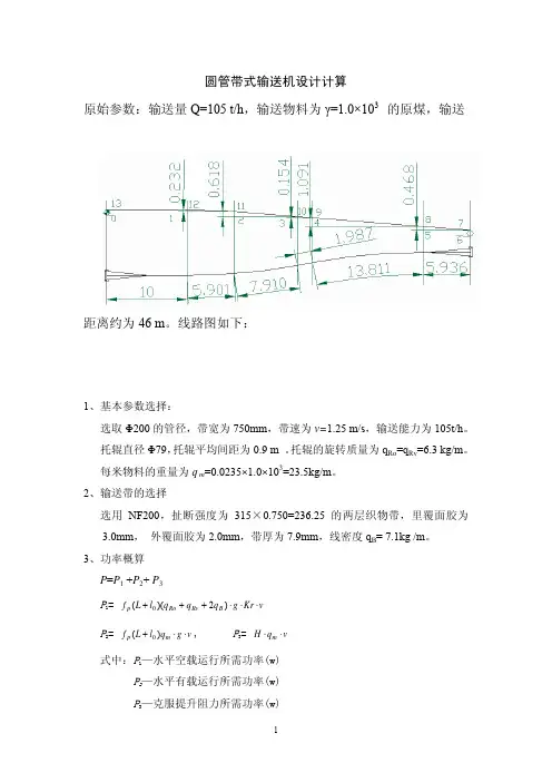
圆管带式输送机设计计算原始参数:输送量Q=105 t/h,输送物料为γ=1.0×103的原煤,输送距离约为46 m。
线路图如下:1、基本参数选择:选取Φ200的管径,带宽为750mm,带速为v=1.25 m/s,输送能力为105t/h。
托辊直径Φ79,托辊平均间距为0.9 m 。
托辊的旋转质量为q Ro=q Rv=6.3 kg/m。
每米物料的重量为q m=0.0235×1.0×103=23.5kg/m。
2、输送带的选择选用NF200,扯断强度为315×0.750=236.25的两层织物带,里覆面胶为3.0mm,外覆面胶为2.0mm,带厚为7.9mm,线密度q B= 7.1kg /m。
3、功率概算P=P1 +P2+ P3P1=vKrgqqqlLfBRvRop⋅⋅⋅+++)2)((0P2=vgqlLfmp⋅⋅+)(0, P3=vqHm⋅⋅式中:P1—水平空载运行所需功率(w) P2—水平有载运行所需功率(w)P3—克服提升阻力所需功率(w)K—考虑托辊及弯曲等的附加阻力系数,取Kr=2.5rL—水平机长l—长度修正系数,取l0=39(m)P1=0.04×(44.76+39)×(6.3+6.3+2×7.1)×9.8×2.5×1.25=2806 WP2=0.04×(44.76+39)×23.5×9.8×1.25=984.18 WP3=23.5×2.65×9.8=622.75 WP=P1+P2 +P3 =2806+984.18+622.75=4413 W4、逐点张力计算取S0=3200 N0—1段为直线路段,水平长度L=10 m ,提升高度h=0 m,加上清扫器阻力。
S1= S0+ f p·L(q Ro+q B)·g+q B·g·h +F r=3200+0.04×10×(6.3+7.1)×9.8+300=3353.6 N1—2段为组合弧段,水平长度L=5.901 m ,提升高度h=-0.232 m。
管状带式输送机的参数计算和结构设计 毕业论文翻译
英文原文Parameters Calculation and Structure Design of Pipe BeltConveyerZaimei Zhang1, Fang Zhou2, Jianheng Ji21School of Mechanical Engineering, University ofJinan, Jinan 250022, Shandong Province,China2Departments ofInformation Engineering, Shandong Water Vocational College, Rizhao 276826,Shandong Province, ChinaAbstract: Pipe belt conveyor is a new type of special belt conveyor and it is wildly used in conveying powder material. In the paper, the advantages of pipe belt conveyor are introduced. Calculation of pipe belt conveyor s main parameters is different from that of conventional belt conveyor s. The parameters such as throughput, belt speed, belt width, resistance, tension in belt and power are described. The length of transition section is analyzed because it is important to the belt life. Hexagon supporting rollers and tipping device are necessary parts ofpipe belt conveyor. The structures of them are also discussed.keywords:Pipe Belt Conveyor, Transition Section,Hexagon Supporting Rollers, Tipping Device1. IntroductionPipe belt conveyor is a new type of special belt conveyor which developed from the conventional belt conveyor. In this conveyor, flat belt is forced to be tubular by supporting roller groups and material conveyed is enveloped in it. Therefore airproof convey is realized in whole conveyance line. Pipe belt conveyor was proposed in 1964 by Japan Pipe Conveyor (JPC), and it went into real use in 1979[1] .After that, it was rapidly developed in Gennany and America and widely used abroad. But it is not deeply studied and its' use is much limited in China.2. The characteristics of pipe belt conveyorFigurel is for the structure of pipe belt conveyor. The load is putted on by the feeder at the end of conveyor.The belt is flat when it runs through the driven roller and it is conducted by a series of supporting rollers to be tubular gradually. Thus airproof conveyance is realized. In order to discharge, the pipe is also conducted by a series of supporting rollers to be flat near the driving roller. The conveyor discharges at its head. Two-way conveyance can be realized. But tipping device for belt must be added. Characteristics are obvious due to its special structure comparing with other belt conveyor[1].(1) Unpolluted conveyanceIn pipe belt conveyor, material doesn't come out and isn't influenced by environment because the belt is tubular and the two sides lap over each other. When itconveys powder, food and chemical material etc., this advantage is obvious.(2) Big obliquity of conveyanceObliquity can reach about 18 in the conventional belt conveyor. But in pipe belt conveyor, material is enveloped in pipe and friction between material and belt is greater than before. So obliquity can be increased to 30 The bigger obliquity is, the shorter conveyance length will be. This can result in lower cost.(3) Two-way conveyance is convenientBelt can be tubular in return of pipe belt conveyor and material can be conveyed in the reverse direction by special device such as special feeder and tipping device.(4) Conveyor bed is narrowIn conveyance, bed is narrow because the cross section is a circle. The required building space and building steel are reduced. The bed cost is low and it can be used when space is limited.3 .Main parameters calculation of pipe belt conveyorMain parameters in pipe belt conveyor are throughput, belt width, belt speed and power. But production throughput is always given.3.1 Calculation throughputThroughput of conveyor can be fonnulated as follows[2]:=Q VFγφ3600Where V is belt speed, F is the pipe area, γis density of material conveyed and φis coefficient of material filling, φ= 0.44~0.8. If material size is less than one third of pipe diameter, φ=0.8. If material size is one third of pipe diameter, φ=0.75. If material size is half of pipe diameter, φ=0.58. If material size is two thirds of pipe diameter, φ=0.44.3.2 Belt speedBelt speed is determined by characteristic of material, throughput, belt width and the installation method of conveyor. Generally speaking, quick belt speed is beneficial because it can reduce belt width and tension in belt when throughput is constant. This will economize on investment in belt and power consumption. Belt speed usually used is 2~5m/s [3].3.3 Belt widthBelt width can be calculated according throughput. The belt diameter can be expressed [2]:d =Where d is pipe diameter.The lap of two sides is about one third or half of pipe diameter. When belt is tubular, the relationship between belt width and pipe diameter is as follow: ((1/31/2))B d π=+3.4 Running resistance calculationThe method has no difference in resistance calculation between pipe belt conveyor and conventional belt conveyor. Generally, Coefficient of resistance is usually used in resistance calculation. Tension in belt is calculated point by point. Extrusion force is increased because material is enveloped in pipe. Therefore coefficient of resistance in pipe belt conveyor is greater than that in conventional belt conveyor.(1)Resistance in tangentResistance in belt with load [2]:01201()cos ()W q q q gl q q Hg ωβ=++±+Resistance in belt without load:030()cos W q q gl q Hg ωβ=+Where W is resistance in running, 0q is the unit mass of belt per meter, 2q is the average unit mass of the upper supporting rollers per meter along the belt, 1q is the unit mass of material per meter along the belt, 3q is the average unit mass of the below supporting rollers per meter along the belt, l is the length of conveyance, β is obliquity of conveyance and ω is coefficient of resistance in supporting rollers, showed in table 1.Table 1.Coefficient of resistance in supporting rollers(2) Resistance in curvatureResistance in curvature is caused by belt ossification and friction in roller bearings. It is proportional to the tension at curvature entrance. That is [2] :1i i S CS -=Where i S is the tension in belt at curvature exit, 1i S - is the tension in belt at curvature entrance and C is coefficient of resistance.3.5 Tension calculation in beltAfter resistance in each section has been calculated, we can calculate the tension at every point. We can divide whole path into several tangents and curvatures and number every joint before we calculate. Tension at any point is calculated by the formula as followed [2]:1(1)i i i i S S W --=+Where i S and 1i S - are tension in belt at point i and point 1i -, (1)i i W - is resistance between point i and point 1i - .The tension at driving roller entrance and driving roller exit can be obtained. Circumferential force on driving roller can be described by following expression:1n P S S =-Where P is circumferential force on driving roller, n S is the tension in belt at driving roller entrance and 1S is the tension in belt at driving roller exit.The following condition must be satisfied because the belt do not permitted to slide on driving roller [2].1n S S e μα≤Where μ is the coefficient of friction between the belt and driving roller, α is angle of the belt enveloping on the roller.3.6 Power calculationPower is mainly consumed in overcoming running resistance. And some power is used in elevating material in sloping conveyor. Power on driving roller shaft can be calculated by the follower expression [2]:01000PV N = So the motor power is:KN N η=Where K is a factor of safety and η is transmission device efficiency.4 Structure design of pipe belt conveyor 4.1 The length of transition sectionFigure 2 Length of transition sectionTransition section is shown in figure 2. The belt is flat at driving roller and driven roller. The belt is turned from flat belt into tubular one at transition section. The length of transition depends on the permissible extension of belt. If transition section is too short, additional deformation and stress will be great in both sides of belt. This will result damage to belt. If transition section is too long, distance of airproof conveyance in whole line will be shortened. Generally speaking, the length of transition section equals to 25 diameters in nylon belt while 50 diameters in wire rope belt [3].4.2 Design of supporting rollersParallel supporting rollers must be used near driving roller and driven roller so that the angle of the belt enveloping on the roller is big enough. But at other position in transition section trough supporting rollers are used. Thus the flat belt can become tubular one gradually and additional stress at edge of belt can be reduced. So trough angle is usually 20°,30° ,45° ,60° and 90°. Since impact load at material entrance is inevitable, three groups of cushioning supporting rollers can sever to reduce the intensity of shock loads and its' spacing is about 300~500mm [4].Hexagon supporting rollers are widely used after the flat belt becomes tubular onel5J • Rollers can be equipped on the same side or two sides of the supporting board. is easy to positioning rollers precisely and the force in belt is uniform when the six rollers are equipped on the same side of supporting board. Generally speaking, the adjacent rollers spacing should not exceed the belt thickness, usually 4~8mm. If thespacing were too big, the edge of belt would jam in it. There are three rollers on each side of the supporting board when rollers are equipped on two sides of it. The length of roller can be longer than the length of hexagon side and the belt can not jam in the space of adjacent rollers. On the other hand, the force in supporting board is uniform. Rollers on supporting board are shown in fig.3 and fig.4.Figure 3 .Rollers on same side of suppporting boardFigure 4. Rollers on two side of suppporting boardRigidity is greatly increased after flat belt becomes tubular. So supporting rollers spacing can also be increased. Supporting roller groups spacing with load is about 1.2m or 1.0m and it is 3.0m in return in conventional conveyor, while it varies with the pipe diameter in pipe belt conveyor. The greater pipe b diameter is, the greater the spacing is[5]. The relationship etween pipe diameter and the spacing is shown in table 2[5].Table 2. The relationship between pipe diameter and supporting roller groups spacing4.3 Belt tipping deviceRemnant material on belt will pollute environment and adhere to rollers and supporting rollers after discharge. This will result to belt wear. So the same side of belt is always used when conveying material. Belt tipping device severs to overturn the belt [6]. It consists of several rollers. The belt is hold by two horizontal rollers and two vertical rollers and tum 90° Then another two horizontal rollers hold the belt and tum it 90° at the same direction. Thus belt overturn is realized. The spacing between horizontal rollers and vertical rollers depends on belt width and operation conditions.5. ConclusionCompared with conventional belt conveyor, pipe belt conveyor has so many advantages that it will be widely used in the future. When calculating parameters, some formals in convention belt conveyor can be used in pipe belt conveyor, but some coefficients must be modified. The power is greater in pipe belt conveyor than in conventional belt conveyor because friction is great in pipe belt conveyor. The transition section length depends on the belt type and pipe diameter. Parallel supporting rollers and trough supporting rollers in conventional belt conveyor can also be used in pipe belt conveyor, but trough angle varies with the poison where trough supporting rollers are installed. Hexagon supporting rollers and tipping device exist only in pipe belt conveyor and their structure is described in this paper. Supporting roller groups spacing also varies with pipe diameter.References[1] Kai Liu, "Application and Development of Pipe Belt Conveyor", Coal Technology, 2006,25(09): 19-21[2] Maton A E, "Power and Capacity Review of Tubular Pipe and Trough Conveyor", Bulk Solids Handing, 1997,17(1):47-50[3] Zhiping Li, "Application of Pipe Belt Conveyor in Bulk Handling", Electric Power Survey &Design,2003,1:48-52[4] Weigang Song, Ye Yu, "The Development and Critical Techniques of the Pipe Belt Conveyor", Cement, 2005,04:42-46[5] Yuefeng An, "Pipe belt conveyor", S P & BMH Related engineering. 2006,2:39-42[6] Gregory A Vaka, "Pipe Conveyor---Development and Advantages", Bulk Solids Handling, 1998,18(3):451-455中文译文管状带式输送机的参数计算和结构设计张在美1,周芳2,纪健恒21.济南大学机械工程学院,中国,山东济南2500222. 山东水利职业学院信息工程系,中国,山东日照276826摘要:管状带式输送机是一种新型的专用带式输送机,它可广泛应用于粉状物料的运输。
JIS8805胶带机计算-LDH
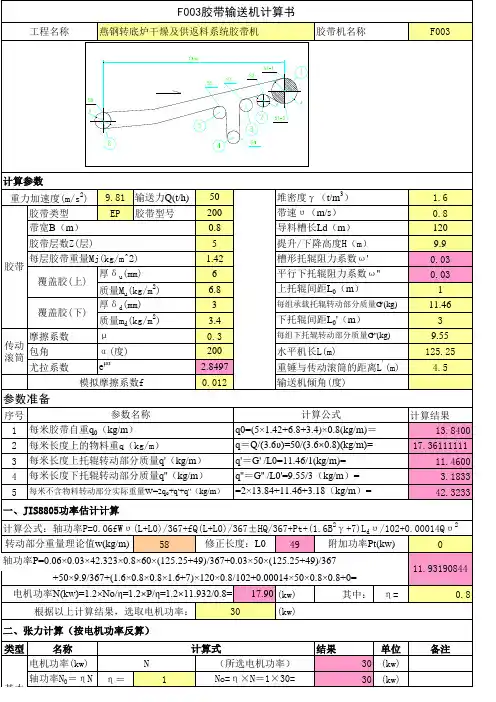
工程名称 燕钢转底炉干燥及供返料系统胶带机 胶带机名称 F003
计算参数 重力加速度(m/s2) 胶带类型 带宽B(m) 胶带层数Z(层) 胶带 每层胶带重量Mj(kg/m^2) 厚δ u(mm) 覆盖胶(上) 质量Mu(kg/m2) 厚δ d(mm) 覆盖胶(下) 质量md(kg/m2) μ 摩擦系数 α (度) e
=5× (13.84+17.36)× 1× 9.81=
37523.125 0.540641682 57809.69041 20286.56541 1344.12696 1530.4145
(N) (N) (N) (N) (N)
基本 倾斜张力 力参 松垂张力 T4=5(q0+ q )L 0.g 数 回程胶带运行 T5=f(q0+ q'')(L+L0).g 阻力 f 0.03 S1-1 各点 张力 (重 锤拉 紧) S1-2 S2 S3 S4 S5 S6 增加配重重量(kg): 滚筒名称 传动滚筒 滚筒 头部增面轮 合张 拉紧改向轮1 力 拉紧改向滚筒 拉紧改向轮1 尾部滚筒 155 90 0 80 0 P(1+K2)或T4+T3+P-T5 P*K2或T4+T3-T5=S1-1-P P*K2或T4+T3-T5=S1-2
参数说明:Fmin:【张力表】中计算出的承载(回程)分支最小张力;L0、L0':承载分支最小张力处托辊间距;q:单位长度上物 料重;q0:单位长度上胶带重;[(h/a)]:输送带许用最大垂度。Fmin':按照选择的电机功率计算的最小张力(kg)。
参数
承载 回程
L0(L0')
q 1 17.361 3 17.361
胶带机计算书
(八) 、电机功率
PM
PA
、 、、
37.84 45.26KW 0.88 0.95 1
( ——传动效率取: = 1 2 一般在 0.85~0.95 之间选取; 1——联轴器效率,机械式联轴器: 1=0.98,液力耦合器: 1=0.96; 2——减速器传 动效率,二级减速机: 1=0.98×0.98=0.96, 三级减速机: 1=0.98×0.98×0.98=0.94; = 1 2=0.96×0.98×0.94=0.88;
满足要求。 【 E ff ——接头强度保持率(一般去 90%) ;
FS ——启动制动时的过负荷张力,其值应小于等于 0.4 Fmax ;
FB ——在滚筒上的弯曲附加里。
】 3、核算传动滚筒直径
D 1000 222 >145,满足要求 。 d 4.5
【d——钢丝绳直径,ST1250 d=4.5mm】 (七) 、计算各滚筒合张力,确定各滚筒直径 头部驱 180 ̊驱动滚筒已确定 φ 110×105 尾部 180 ̊ 改向滚筒: 合张力:F=F0=63.25KN 设计选用手册(TK 型滚筒) :初选滚筒 D=800mm,代号 D7B2P512(许用合力 98KN) 头部 45 ̊ 改向滚筒 合张力:F =6731.6=6.7KN 由设计选用手册(TK 型滚筒) :初选滚筒 D=500mm,代号 D7B2P36(许用合力 21KN) (八)、凹弧段曲率半径计算
1、加料段物料加速和输送带间的惯性阻力及摩擦阻力(4 个加料段) FbA=Ivρ (V-V0)=SVkρ (V-V0)=Q/3.6*(V-V0)=555.56*(3.15-0)=1750.014N/4 四个受料点:FbA=1750.014/4*4=1750.14N 2、加料段加速物料和导料槽两侧栏板间的摩擦阻力(4 个加料段)
胶带机功率及能力计算
154.7m 注:本程序只适用于非水平且长度50米以上的功率1.25m/s 当胶带机为水平或者长度小于170t/h 计手册下册286页中K3系数的取值,环境按少量2.6m 正常湿度的情况考虑 N1= 2.39785 N2= 2.148628 N3= 1.20666N0= 6.903766胶带机电动机的功率为N=10.98389KW135.1m1.6m/s 300t/h 12mN1= 3.56664 N2= 3.311301 N3=9.828N0=20.04713胶带机电动机的功率为N=31.89498KW107m 1.6m/s 900t/h 0mN1= 3.92048 N2=7.86771 N3=N0=14.14583胶带机电动机的功率为N=22.50601KW0.65m 注:1本程序计算的是皮带机的大概能力,仅供参1.25m/s 若所输送物料水份较大,则在计算出来的能力0.9t/m 3 校正系数1.08;若输送物料水份较少,则在计171.1125t/h的能力上乘以校正系数0.920.8m 注:2本程序是以胶带机倾斜角度˚时取倾角系1.6m/s 计算所得,若胶带机倾角≤6˚,则倾角系数取0.9t/m 3≤6˚8˚10˚368.64t/h10.960.94当带宽为500和650时:胶带机的带宽B= 胶带机的带速V=输送物料的容重γ= 胶带机的带速V=输送物料的容重γ=当带宽为800和1000时:胶带机的能力G=胶带机的能力G= 胶带机的带宽B=1.胶带机带宽为650mm时:2.胶带机带宽为800mm时: 胶带机的水平投影长度L= 胶带机的带速S= 胶带机的水平投影长度L= 胶带机的带速S= 胶带机的输送能力G= 胶带机的垂直提升高度H=胶带机能力的计算: 胶带机的带速S= 胶带机的输送能力G= 胶带机的垂直提升高度H= 胶带机的输送能力G= 胶带机的垂直提升高度H=3.胶带机带宽为1000mm时: 胶带机的水平投影长度L=非水平且长度50米以上的功率计算度小于50米时请查阅水泥设页中K3系数的取值,环境按少量尘埃、是皮带机的大概能力,仅供参考选型用水份较大,则在计算出来的能力上乘以;若输送物料水份较少,则在计算出的校正系数0.92斜角度为12˚时取倾角系数0.92角≤6˚,则倾角系数取1.012˚14˚16˚0.920.90.88。
胶带输送机选型计算2[1]
胶带输送机选型计算胶带输送机选型主要确定以下问题: 1. 确定胶带输送机带速v :根据国家带速标准化和井下煤炭等材料的运输情况,通过参考相关资料,初步确定带速为v =2m/s.2. 确定胶带宽度B :已知Q =400t/h, γ=960kg/m ³,v =2m/s 查得输送带倾斜系数k =0.94(β=10.5°) 煤炭断面积A =kv Q..6.3γ=94.029606.3400⨯⨯⨯=0.0616 m ³ 式(2-1) 槽角取30°,动态堆积角θ=10°,查表B =1000mm3. 求圆周力U F =H F +N F +1S F +2S F +St F =C.f.L[(2q B +q G )cos β+q RO +q RU ]+ q G .H.g+1S F +2S F 其中:C ——附加阻力折算系数,查得C=1.17;H F ——运行主要阻力;H F = f.L.g[(2q B +q G )cos β+q RO +q RU ] 式(3-1) =0.025×600×9.81[(2×25.44+83.33)cos10.5°=23084N 式(3-1)中:f ——模拟摩擦系数,取f=0.025; L ——输送机长度;g ——重力加速度,取g=9.81m/s ²; β——输送带工作倾角;q B ——输送带每米质量,查得25.33kg/m ; q G ——物料每米质量;q G =v Q 6.3=26.3600⨯=83.33kg/s ; q RO ——承载分支托辊每米旋转质量;q RO =RO RO l m =2.122=18.33kg/s ; 其中:RO m ——承载部分托辊质量,kg; RO l ——承载托辊间距,m ; q RU ——回程分支托辊每米旋转质量;q RU =RURU l m =5.217=6.8kg/s; 其中:RU m ——回程部分托辊质量,kg; RU l ——回程托辊间距,m ;F N ——附加阻力当输送带长度大于80m 时,采用折算系数法计算主要阻力和附加阻力,即:H F +N F =C H F =1.17H F =1.17×23084=27008N ;1S F ——特种阻力1S F =Sa F +Sb F =εC .0μ.εL .g[(q B +q G )cos βsin ε+0=0.4×0.35×600×9.81×(25.33+83.33)cos10.5°×sin2° =3123N式中:Sa F ——托辊前倾阻力,Sa F =εC .0μ.εL .g[(q B +q G )cos βsin εεC ——槽形系数,εC =0(30°槽角)0μ——托辊与输送带之间摩擦系数,取0.35; εL ——装有前倾托辊区段长,近似取600; ε——托辊前倾角; 不设挡煤裙板Sb F =02S F ——特种阻力;2S F =Sc F +Sd F =700B+a K .B=700+1000=1700N式中:Sc F ——清扫器摩擦阻力,Sc F =700B; Sd F ——卸料器摩擦阻力,Sd F =a K .B ; B ——带宽,m ;a K ——阻力系数,1500N/m ; St F ——倾斜阻力St F = q G .H.g=83.33×600×sin10.5°=9112N 将以上相关数据回代U F =27008+9112+3123+1700=40943N4. 各点张力计算:考虑井下潮湿条件,摩擦储备系数n 取1.5,围抱角α=1α+2α=180°+180°=360°1F =max F =U F (1+μαe n )=12714×(15.1225.0+∏⨯e )=17030N2F =max F /μαe =17030/4.8=35450Nk F = q B . f.L.g.cos β+ q RU f.L.g.sin β=-22504N zh F =(q B +q G ).(f.cos β+sin β).L.g+ q RO f.L.g=129577N3F ≈2F =35450N4F =3F +k F =35450-22594=12946N5F =6F -zh F =1F -zh F =170340-129577=40763N 5. 校核垂度重段垂度所需最小张力:min F ≥ROmax RO G B l f 8. l ).g. q + (q =02.081.29.81) 83.33+ (25.33⨯⨯⨯=7995N5F >min F 通过min /F ≥RUmax RU B l f 8. l g. q =02.081.29.81 25.33⨯⨯⨯=1864N4F >min /F 通过 6. 校核胶带安全系数:m=max.F B b σ=12151410012500⨯=10.2>10 通过7. 电动机功率确定:N=mU vF η1000.=(40943N*2) /(0.85*1000)=96.4Kw功率储备:1N =1.3N=1.3×96.4=125.4kW考虑采取供电电压及环境要求预选两台YB 系列100kW 电动机8. 拉紧力计算h F =4F +5F =12946+40763=53709N。
胶带输送机设计计算书120 3X315
胶带输送机设计计算书DSJ120/150/3X315山西潞安甲义晟矿山设备有限公司一、原始参数1.运输物料:原煤;松散密度:γ= 900 kg/m32.运输能力:第一个给料点Q1=1500.00 t/h(自尾部起)第二个给料点Q2=0.00 t/h 第三个给料点Q3=0.00 t/h 第四个给料点Q4=0.00 t/h3.水平运输距离:L= 2200.000 m1).第一、二给料点距离:L21= 0.000 m2).第二、三给料点距离:L32= 0.000 m3).第三、四给料点距离:L43= 0.000 m4.胶带倾角:第一段β1= 0.00 ° = 0 弧度(自尾部起)第二段β2= 0.00 ° = 0 弧度第三段β3= 0.00 ° = 0 弧度平均角度= 0.00 ° = 0 弧度5. 胶带速度:ν= 3.15 m/s6. 提升高度:H= L'×tgβ= 0.00 m二、自定义参数1. 胶带种类:钢丝绳芯胶带,上覆盖胶厚度8mm,下覆盖胶厚度8mm2. 胶带宽度:B= 1200 mm = 1.20 m3. 胶带强度:σ= 2000 N/mm4. 输送机理论运量: Q= 3.6Sνkγ式中:S—输送带上物料最大截面积;S= 0.26400 m2k—倾斜输送机面积折减系数;k= 0.92Q= 2478.833 t/h大于Q1= 1500.000 t/h根据实际带速,计算实际运量Q=3.6SνkγQ实际= 2472.217 t/h大于Q1= 1500.000 t/h5.每米机长胶带质量: q0= 32.340 kg/m6.每米机长物料质量: q= Q/3.6ν= 132.275 kg/m7.滚筒组:(1)头部传动滚筒D≥Cod 式中:钢丝绳d= 0.0040 m= 0.600 m Co= 150.0000传动滚筒直径D= 1000.0000 mm(2)尾部及主要改向滚筒直径= Φ630 mm8.托辊组:⑴重载段:采用35°槽角托辊组,辊子直径=Φ133 mm辊子轴承型号:6306/C4 , 辊子轴径Φ30 mm,查表单个上辊转动部分质量q r0'= 10.53 kg n= 3 a0--上托辊组间距;a0 = 1.50q r0= nq r0'/a0= 21.060 kg/m每米机长上辊子旋转部分质量: q1= 21.060 kg/m⑵空载段:采用V型下托辊组辊子直径=Φ133 mm辊子轴承型号:6306/C4 , 辊子轴径Φ30 mm,查表单个下辊转动部分质量q r0'= 14.00 kg n= 2 a0--上托辊组间距;a u = 3.00q r0= nq r0'/a u= 9.333 kg/m每米机长下辊子旋转部分质量: q2= 9.333 kg/m⑶辊子旋转转速: n= 30×ν/(3.14×r)= 452.34 rpm⒑上下胶带模拟阻力系数:ω= 0.0230⒒胶带与传动滚筒之间的摩擦系数:μ= 0.3500⒓拉紧方式:液压拉紧,拉紧位置在头部,至头部距离: L1= 45.0000 m⒔清扫方式:头部布置H型合金橡胶清扫器,尾部布置角型硬质合金清扫器⒕导料板长度: l= 4.5000 m⒖头部设置2组过渡托辊组,给料点下设置10组缓冲托辊组三、输送机布置型式(下运)头部为双滚筒三电机驱动四.辊子载荷校核⑴净载荷校核①重载段辊子校核P0= ea0g(Im/v+q0)= 1937.85 N 式中: e--辊子载荷系数;e= 0.80Im--输送能力;Im= Q/3.6= 416.67 kg/s 辊子额定载荷P0e= 2920.00 N 故满足要求。
- 1、下载文档前请自行甄别文档内容的完整性,平台不提供额外的编辑、内容补充、找答案等附加服务。
- 2、"仅部分预览"的文档,不可在线预览部分如存在完整性等问题,可反馈申请退款(可完整预览的文档不适用该条件!)。
- 3、如文档侵犯您的权益,请联系客服反馈,我们会尽快为您处理(人工客服工作时间:9:00-18:30)。
管状胶带机设计计算实例➢管带机的发展及其优势管状带式输送机是在普通带式输送机基础上发展起来的一种新型带式输送机。
它是通过呈六边形布置托辊,将胶带强制裹成边缘互相搭接的圆管来对物料进行密闭输送的。
由于管状带式输送机是从普通带式输送机发展而来的,由于它的传动原理与普通带式输送机完全相同,是一项成熟技术,因此得到用户的普遍认可。
目前,管状带式输送机技术日趋标准化,它的结构特点决定了未来它将是一种应该优先选取的散料输送方法。
管状带式输送机的应用基本没有限制,只要物料粒度均匀,基本上任何散状物料都可采用。
常用来输送的典型物料有矿石、煤、焦炭、石灰石、沙石、水泥烧结料、化工粉料和石油焦等。
一些非常难处理的物料,如钢浓缩物、粘土、废渣、碎混凝土、金属碎渣、加湿粉煤灰、尾渣和铝土等也可用管状带式输送机输送。
➢管带机的特点:1. 可广泛应用于各种粒度均匀的散状物料的连续输送;2. 输送物料被包裹在圆管状胶带内输送,因此,物料不会散落及飞扬;反之,物料也不会因刮风、下雨而受外部环境的影响。
这样即避免了因物料的撒落而污染环境,也避免了外部环境对物料的污染;3. 胶带被六只托辊强制卷成圆管状,无输送带跑偏的情况,管带机可实现立体螺旋状弯曲布置。
一条管状带式输送机可取代一个由多条普通胶带机组成的输送系统,从而节省土建(转运站)、设备投资(减少驱动装置数量),并减少了故障点,及设备维护和运行费用;4. 管状带式输送机自带走廊和防止了雨水对物料的影响,因此,选用管状带式输送机后,可不再建栈桥,节省了栈桥费用;5. 输送带形成圆管状而增大了物料与胶带间的磨擦系数,故管状带式输送机的输送倾角可达30度(普通带式输送机的最大输送倾角为17°),从而减少了胶带机的输送长度,节省了空间位置和降低了设备成本,可实现大倾角(提升)输送;6. 管带机的上、下分支包裹形成圆管形,故可用下分支反向输送与上分支不同的物料(但要设置特殊的加料装置);7.由于输送带形成管状,桁架宽度较相同输送量的普通带式输送机栈桥窄,从而减少占地和费用。
➢管带机的结构特征管带机是在普通带式输送机的基础上发展起来的一种新型带式输送机,它和普通带式输送机的工作原理基本相同,它是利用按一定间距布置的多边形(正六边形最好)托辊组强制使胶带卷成圆管状, 如图1所示。
其工作过程是:物料从尾部加料漏斗处进入加料段,输送带由平形变为u形,再经过过渡段逐渐变为圆管状,把物料包住密闭运行,输送到头部过渡段时,圆管状输送带由u形渐渐展开成平形,把物料卸掉。
承载回程分支输送带也可形成圆管状运行,或回程分支以平形运行。
胶带是管带机承载物料的承载件和牵引件,管带机使用的胶带主要有:尼龙、聚酯织物芯和钢丝绳芯胶带。
如图2所示结构,管带机要有良好的弹性、纵向柔性、适当的横向刚性和抗疲劳性能;对带芯要求严格,带芯必须具有一定的强度和牢度;两边搭节部分要有良好的可挠曲性,以保证胶带在成管后的密封性和稳定性能。
胶带两边搭接的长度推荐为管径的1/2,则带宽与管径的关系为:B=(π+1/2) d 管(式中:B-胶带的宽度,m ,d 管-管带机的管径,m )管带机与其它输送带不同技术指标是横向刚性,这是管带机胶带独特技术指标。
而且每条胶带的宽度不同,厚度不同,它的刚性就不同。
胶带刚性通常的测量方法时:取75 mm 长的胶带,用105g →400g 的力垂直作用在胶带上,测得的弹力值为胶带的刚性强度。
胶带型号的选择要考虑胶带的最大张力值、输送距离、使用条件及安全系数。
胶带的安全系数是一个经验值,应考虑安全、可靠、寿命、制造质量、经济成本、启动系数、现场条件等多方面的因素。
依据DT Ⅱ安全系数n 的推荐,对钢丝绳芯输送带:n=7~9;对织物绳芯输送带:n=12~16。
运行条件好,倾角小,强度低,取最小值,反之,则取最大值。
当输送距离在2km 以内时,宜适用织物芯胶带,安全系数最小取12,其使用伸长率不得大于2%;当输送距离大于2km 时,宜适用用钢丝绳芯胶带,安全系数最小取7,其使用伸长率不得大于0.2%。
管带机托辊主要有六边形托辊组、槽形过渡托辊组。
槽形过渡托辊组用于头部和尾部的过渡段,其结构和布置间距与普通带式输送机相同,根据过渡段长度可选用10°、20°、30°、45°、60°几种。
六边形托辊组的布置间距随管带机圆管直径的增大而增大,在确定间距时,还应考虑到输送物料的松散密度转弯半径和弧段类型等。
由于管带机为桁架结构,中间段一般不设栈桥,因此对管带机辊子的防水性能要求较高。
4. 桁架和支架由于管带机可以沿着地平线和架空等多种布置形式,根据现场的需要而定。
为了安装管带机托辊架,因此管带机一般选用如图3形式的框架(即桁架),支撑选用圆钢管人字形支架,由于管带机桁架已有足够刚度,则可在两边另加人行通道和检修通道,从而取代输送机栈桥。
2.5其他部件:驱动装置、传动滚筒、改向滚筒、拉紧装置、头尾架、导料槽、头部护罩、漏斗、尾部护罩、头部清扫器、空段清扫器等部件结构与普通带式输送机结构完全一致。
➢线路布置1.布置线路应注意的问题:管带机可以实现空间曲线输送线路布置,当具有较多的弯曲段时,最好使弯曲段的数量和方向在输送机两侧对称布置,以保证胶带在运行时张力在其横断面上均匀分布,减少扭曲;管带机的过渡段长度主要由胶带的伸长率和横向刚度决定的。
在过渡段,胶带由平形变成圆形,此时胶带的边缘将被拉伸,并由此产生附加应力。
如果过渡段太短,则胶带边缘将产生很大的附加应力,使其过早地疲劳破坏,严重时甚至使胶带边缘撕裂;如果过渡段太长,x25;钢丝绳又将缩短整个输送线路的密封长度。
对尼龙帆布胶带:过渡段长度通常取Lg=d管芯胶带:过渡段长度通常取Lg=dx50。
管管带机不适用于中间设有加料点和卸料点。
如果必须在输送段中间设加料点或卸料点,一般采用增加过渡段将胶带展成平形的方式,在加料点安装加料装置加料,或在卸料点采用电动或手动犁式卸料器直接卸料。
2.输送路线空间弯曲布置时的曲率半径管带机的输送路线可以绕过建筑物、跨过河流和公路等,在空间任意方向按曲线布置,省去了中间转载,能实现一机长距离复杂线路输送物料。
但值得注意的是:曲率半径的大小直接影响到胶带和托辊的使用寿命,因此在现场布置允许的情况下要尽量增大曲率半径。
曲率半径应满足下列要求:x300尼龙布胶带:转弯半径R≥d管x600钢丝绳芯胶带:转弯半径R≥d管➢管带机安全保护措施1.关于扭曲问题:胶带调试好以后运行可靠性很高,输送带在发生正负20度范围内的偏转属于正常偏转,当发生20到90度范围内的偏转时属于轻度偏转,按调整方法大约在2小时以内能完成,当发生90到180度范围内的偏转时属于重度偏转,按调整方法要多调整几组托辊,大约在4小时以内能完成。
业主应每天进行巡回检查一次。
供方保证一周内不会发生大于180度扭转。
当胶带扭转45度时,须及时进行调整。
轻度扭转可不调整;中度扭转可不停机加调整垫片进行调整,调整周期一般为2-8小时即可完成;重度扭转可不停机加调整垫片进行调整,调整周期一般为4-16小时即可完成;严重扭转应停机,人工纠正后,加调整垫片后再空载和重载进行调试,调整周期一般为2-4天。
破坏性扭转的调整方式与严重扭转的调整方式相同,调整周期一般为3-5天,如果调整还达不到要求,可增加托辊,并将托辊安装位置旋转30°安装后再进行调试。
在使用中胶带发生扭转时应及时调整,以免发生严重扭转和破坏性扭转。
2.关于正常运行情况下的物料最大充满度在管带机尾部过渡段设置限料装置以控制物料充满度。
当充满系数在小于75%状态下,可保证长时间安全运行。
3.关于六边形托辊之间的间隙:管状胶带机PSK托辊安装架采用模具加工,制造精度高,保证六边形托辊之间的间隙在0.5~5.0mm之间,能有效防止胶带嵌入托辊间隙引起损坏。
4.管带机其它的安全保护措施与普通胶带机相同,如在管状胶带机头尾过渡槽形段设有调心托辊以防止胶带跑偏,设有拉绳开关、防撕裂、防堵等保护设施。
➢设计计算管带机功率计算方法和普通胶带机功率计算方法基本相同,不同的地方主要体现在:运的选取及管带机各种附加阻力的计算方法。
行阻力系数fP1.运行阻力系数fp的选取管带机的运行阻力系数与普通胶带机的模拟摩擦系数f相似,但由于管带机在运行时被迫卷成管状,与普通胶带机又有区别。
根据业主提供的参考资料,管带机的运行阻力系数fP 可按下表选用:2.胶带的附加阻力管带机与普通胶带机不同的还体现在各种附加阻力上,如成形阻力、弯曲阻力、刚性阻力等附加阻力。
胶带的弯曲阻力可以按DT75来计算,即F=T*(π/180)*θ*fp,其中T为弯曲点胶带的受力;胶带的刚性阻力可以用g/75mm来表示,F=71*fp*D/75,其中D为管胶直径;胶带局部阻力主要包括加料阻力和清扫器阻力,可按DTⅡ型带式输送机中的有关计算方法计算;胶带的成形阻力比较小,计算中可以忽略。
➢管带机设计选型计算实例1.布置参数某厂除灰用管状胶带机的用途是将灰库下的调湿灰从厂区内送至灰场,管带机展开长度为988m,除365m在厂区内外,其余623m布置在野外,沿线共跨过一条马路、一座桥、四个山头、穿过村庄和村沟,最后伸进灰场。
其中水平弧段1个,垂直弧段5个,在设计时避开了立体弯。
凹弧段和平面处转弯半径为200m,凸弧段转弯半径为175m,管状段直线段托辊间距为1600mm,曲线段托辊间距为1100mm,过渡段长度为10.50 m,最大水平转弯角为27.02°,最大倾角为6.37°。
整条胶带机采用桁架结构,管带机窗式框架宽620mm,运行通道静宽为1m,检修通道净空为0.7m,桁架合计宽2320mm。
桁架间距一般为12m,最大跨距为21.5m,在管带机沿途设了7个防震支架和3个中间出口,在管带机头尾部还设置有维护检修用的出入口。
桁架挠度按L/800计算。
2.输送参数:计算图如下:(0)-(1)段阻力L1=343m,H1=0承载分支=(qB+qru+qg)*f*L1+( qB+qg)*H1+L1*f*D/75=(18.4+7.3+33)*0.039*343+(18.4+33)*0+34 C013*0.039*250/75=833kg回程分支R=(qB+qr0)*f*L1+qg*H+71*f*D/75=(18.4+7.3)*0.039*343+33*0+343*0.039*250/75=388kg 01(1)-(2)段阻力L2=71m,H2=7.9m承载分支C=(qB+qru+qg)*f*L2+( qB+qg)*H2+L2*f*D/75=582kg12回程分支R=(qB+qr0)*f*L2+qg*H2+L2*f*D/75=-63kg12(2)-(3)段阻力L3=225m,H3=16.3m=(qB+qru+qg)*f*L3+( qB+qg)*H3+L3*f*D/75=1390kg承载分支C23=(qB+qr0)*f*L3+qg*H3+L3*f*D/75=-45kg回程分支R23(3)-(4)段阻力L4=100m,H4=-8.1m=(qB+qru+qg)*f*L4+( qB+qg)*H4+L4*f*D/75=-176kg承载分支C34回程分支R=(qB+qr0)*f*L3+qg*H3+L4*f*D/75=262kg34(4)-(5)段阻力L5=249m,H5=22m=(qB+qru+qg)*f*L5+( qB+qg)*H5+L5*f*D/75=1743kg承载分支C45回程分支R=(qB+qr0)*f*L5+qg*H5+L5*f*D/75=-123kg45转弯阻力:=T*(π /180)*θ*f=4668*3.14/180*6.4*0.039=20.3kgC(1)C=5250*3.14/180*27*0.039=96.4 kg(2)=6640*3.14/180*9*0.039=40.7kgC(3)C=6464*3.14/180*11*0.039=48.4kg(4)=3220*3.14/180*6.4*0.039=14kgR(1)R=3283*3.14/180*27*0.039=60.3kg(2)=3328*3.14/180*9*0.039=20.4kgR(3)R=3066*3.14/180*11*0.039=22.9kg(4)传动滚筒轴所需功率P A:ΣP A=100.37Kw,Fu=ΣP A*102/v=100.37*102/2=5119kg 驱动电机轴所需功率P M:P M=P A/η=100.37/0.838=119.8Kw,功率系数K :1.2电动机功率P=K* P M =1.2*119.8=143.8 Kw,选160kW的电机。