
《网络规划与设计》课程设计指导书(成)
《网络规划与设计》课程设计指导书(成)《计算机网络规划与设计》课程设计说明书(黑体2号)一、课程的性质、目的和任务 (黑体小三)《网络规划与设计》课程是计算机网络工程专业的一门专业实践课,其主要内容是规划和设计一个中小型网络,课程设计所涉及的工作过程主要包括网络工程招标文件的写作、网络工程标书的写作、网络方案的设计、网络方案的推广、网络方案的实现。
通过本课程设计,使学生全面了解和掌握网络工程规划和设计的方法,了解计算机网络工程规划与设计的一般过程,具体包括在自顶向下的网络设计方法中需求分析、逻辑设计、物理设计、优化测试及文档编写,从而可以完成一些类似于校园网或者中小型企业的网络的规划和设计,形成一个详细的设计方案。
要求根据对中小型网络分析,设计与构建的基本技术,基本原理,并且最后形成一个详细的网络规划与设计的文档。
从而提高学生网络工程的应用能力,使学生可以提高学生分析问题和解决问题的能力和团队协作的能力。
14课程目标设计1、能力目标(1)能理解并熟悉常见中小型企业的网络系统集成方案;(2)能独立完成中小型网络设计前需求分析方案的设计,并正确分析需求分析结果;(3)能根据需求分析结构,独立完成中小型网络的设计方案;(4)能根据中小型网络设计方案,独立完成方案的组网与实施;(5)能根据项目需求,依据国家相关规定,协助完成网络标书的写作;2、知识目标(1)掌握网络规划需求分析的方法与技巧;(2)掌握逻辑网络设计的方法;(3)掌握物理网络设计的方法;(4)理解网络标书的格式及书写方法;15应用级的安全性、网络级的安全性、数据级的安全性。
由于办公网络用户离不开与外界进行交流,在享受Internet的服务的同时,防范网络病毒、木马等系统和数据的破坏,防止黑客入侵造成数据丢失或泄密等。
统一性:规划设计办公网络,应统一进行规划,统一设计,分步实施,以方便办公网络的后期管理。
完整性:保证整个办公网络的系统功能、数据安全、网络管理等方面应有充分的保证。
经济实用性:每个公司在组建自己内外计算机网络的时候,都需要考虑如何最有效的利用网络资源,使有限的硬件设施获得最优的可用带宽,保证建成的网络安全和规范,并且易于维护、扩展和高效使用。
因此,在设计中要采用先进的、成熟的、实用性强的技术和性价比高网络产品,不盲目的追求设备的高档、技术的超前,以免造成不必要的资金浪费,从而使系统具有较强的实用性。
可靠性与有效性:规划设计时必须从系统结构、设计方案、设备选型、厂商的技术服务与维修响应能力、设备备件供应能力等多方面考虑,尽可能减少故障发生的可能性,缩小影响面。
同时还须考虑与现有办公设备和事务处理的整合。
扩展性与先进性:进行网络规划设计时应具有较好的扩展性,以降低系统扩展的投入成本,并能充分满足信息技术高速发展的需要。
能适应近3-5年内的业务增长和突发性事件的需要,确保各级系统的可扩充性和先进性,并注意设备的冗余设计以及网络的负载均衡。
(3)网络应用Web、FTP、E-Mail、VOD。
2、逻辑设计(1)整体结构设计根据需求分析,以层次化的网络设计方法,选择合适的网络技术,设计一个性能价格比相对优化的网络解决方案,该网络要实现各种资源的兼容性,网络整体安全性、先进性、可靠性,后续网络的可扩展性、易管理性、高有效带宽等。
主要包括:组网技术的选择,子网的划分与隔离,共享资源的配置,应用服务器的设置,IP地址规划等,综合布线系统的规划(工作区子系统,水平子系统,主干子系统,设备间子系统,建筑群子系统,管理子系统,需要考虑机房的安全、布局等等) 。
(2)局部网络结构设计3、物理设计主要是:布线、交换机与路由器配置(1)网络中心的设计(2)每栋楼设计4.网络设计方案的编写以通用的网络方案编制规范撰写一个相应的书面文档,在该文档中要包括需求分析(网络建设的目标与原则)、主干技术的选择、工程总体设计(拓朴结构、功能设计、硬件与软件选择、结构化布线等)、网络管理与安全、投资预算和设备清单。
5、测试(1)确定测试范围(对哪个网段测试)(2)确定测试内容(连通性、性能、故障)三、设计(或上机)内容和基本要求编号能力训练项目名称拟实现的能力目标相关支撑知识及目标训练方式手段及步骤结果(可展示)网络需求调查掌握需求调查的目标、方法和技巧电子表格等统计工具的使用现场调查,实地讲解写出需求调查报告,用图表的方式绘出调查量化结果,指出敏感点。
调查结果分析根据需求调查量化结构,分析网络技术需求知道网络各种常见技术的功能承接上一模块,现场分析写出需求分析报告网络招标能正确反应需求得写出招标书,知道招标的步骤知道招投标规范和要求承接上一模块,模拟招标招标文件一整套逻辑网络拓扑能设计符合需求的网络各种拓扑结构的优缺承接上一项逻辑网络拓扑图及其说明设计拓扑图,能画出拓扑图点,拓扑图的绘制工具目,理实结合逻辑网络地址规划能设计符合需求的网络地址规划方案IP地址的相关知识承接上一模块,理实结合逻辑网络地址规划说明书网络可靠性设计能在现有拓扑结构及地址规划方案基础上进行可靠性优化保障网络可靠性的各种方法承接上一模块,理实结合可靠性设计说明书网络安全性设计能在现有拓扑结构及地址规划方案基础上进行安全性优化保障网络安全性的各种方法承接上一模块,理实结合安全性设计说明书物理网络设计将逻辑网络设计方案具体实现到真实环境综合布线、了解各种主流设备得功能及技术承接上一模块,理实结合物理网络设计说明书网络实现在路由交换设备上实现在现有实验室设备上将方案实现交换路由设备的配置理实一体,实际操作四、参考设计题目:1.规划设计一个拥有200个机位的网吧。
要求从以下几个方面进行设计:1).需求分析(目的,特点,策略).2).网络规划设计①结构选型(拓朴结构) .②Internet接入.③硬件选择(型号,配置).④软件选择(系统软件,管理软件,应用软件).⑤传输介质.3).可行性论证.①传输速度.②用户接口(客户机,操作系统,应用软件,协议).③管理能力(技术, 安全)④投资费用(软件,硬件,安装,布线,培训,维护等).⑤成本回收等.----------------------------------------------------------------------------------------------------------------------------------------2.某中学校园网规划方案的设计设计要求如下:1. 建立办公自动化系统办公楼共有40个信息点。
要求通过校园网连至INTERNET,达到100M到桌面,并对财务科,人事科等科室进行单独子网管理。
2. 建立考试监控系统共有教学楼3座,120个信息点。
(1)综合教学楼一个,60个信息点。
其中有10个实验室,每个实验室配置1台PC和1个投影仪(此处无须上网);20个教室,其中一个教室2个摄像机。
(2)普通教学楼1:40个信息点,共20个教室,其中一个教室2个摄像机。
(3)普通教学楼2:20个信息点,共10个教室,其中一个教室2个摄像机。
3. 建立综合多媒体教室信教中心:共120个信息点。
有两个多媒体教室,每个教室60台PC。
要求可网管,通过校园网上连至INTERNET,达到100M到桌面。
4. 为了满足教职工的需要,提高教职工教学条件和水平,大力发展网上教学,优秀科目科件制作等。
将教职工宿舍区的PC通过校园网上连至INTERNET,达到10M到桌面,以后可扩展到100M 。
5. 学校校园网建设所需PC和投影仪由校方自行选择和安装。
学生宿舍由于高中阶段学习生活的特殊性,不进行任何布置。
----------------------------------------------------------------------------------------------------------------------------------------3.企业网(园区网)设计每一个企业网(园区网)都有自己的特殊性,包括企业网(园区网)的环境和功能需求,这就要求必须针对这些特殊性进行专门的规划与设计。
1). 规划和设计企业网(园区网)的主要步骤:首先,在规划和设计企业网(园区网)前必须进行详细的需求调研,搞清楚用户现有的网络状况以及建网目标。
限于网络方面的专业技术水平,用户往往无法清楚地对需求进行描述,这就需要设计人员揣摩用户的意图,通过各种方式了解用户的需求。
有了需求以后,下一步就是对系统进行分析,对企业网(园区网)中的主要技术进行选型,根据先进性和实用性相结合,经济性和可扩展性相结合,按可靠性、安全性、可管理性、可维护性的原则进行设计。
具体包括主干网技术选型、主干网拓扑结构、Internet接入方式、广域网互连方式、一些组网关键技术等。
接着是进行详细的设计。
首先是设备的选型,设备选型必须在满足功能的前提下,遵循相关的设计原则;然后是VLAN的规划、IP的规划、路由的规划;接着是进行可靠性、安全性的具体规划以及网络的管理规划等。
最后,需要进行综合布线系统设计和机房设计。
2). 企业网(园区网)在规划过程中应遵循的原则。
(1)标准化及规范化:采用开放的标准网络通信协议,选择符合工业标准的网络设备、通信介质、网络布线连接件及其相关器件器材。
工程实施遵照国家电信工程实施标准进行。
(2)先进性与成熟性:按照生命周期的原则,系统设计的基本思想,符合技术发展的基本潮流,使布线系统在其整个生命周期内保持一定的先进性。
选择合理的网络拓扑结构,网络工程中所用的设备、器材、材料以及软件平台应选择与网络技术发展潮流相吻合的、先进的、有技术保证的、得到广大用户认可的厂家产品。
(3)安全性与可靠性:为了保证整个网络系统安全、可靠地运行,首先必须在总体设计中从整体考虑系统的安全性和可靠性。
在网络设计阶段以及在工程实施各个阶段都必须考虑到所有影响系统安全、可靠性的各种因素。
工程实施完成后,必须按照标准进行严格的测试。
----------------------------------------------------------------------------------------------------------------------------------------4.高校校园网的网络规划与设计.高校校园网络的规划设计有多种解决方案,依学校的类型规模和性质的不同,以使网络的设计方案有所不同,体现在技术、应用上更是不同。
学校教师的教学、科研工作和学生的学习生活对一个高速的、资源丰富的和应用多方面的校园网络的需求是迫切的、必需的,也是网络规划与设计者的目标。
设计与规划高校校园网要求:1.设计的校园网方案的设计应符合近、中和长期发展规划依据学校规模大小,结合学校教学科研的内容及其发展的需要,制定一个在未来十年中的近期、中期及长期的建设规划,以保持网络建设的延续性,并保护先前的投资(含各种硬件、软件及信息资源),能融入不断涌现的新技术和新应用。
网络规划与设计实验指导书

实验三 Linux操作系统下TCP/IP协议的配置一、实验目的自选实验。
Linux操作系统的应用逐渐普及,网络中很多服务器都采用Linux 操作系统。
因此在Linux下配置主机信息是网络工程中的重要技能,本实验要求学生能掌握Linux操作系统下TCP/IP协议的配置。
二、实验要求能够在Linux操作系统下熟练地完成TCP/IP协议配置。
三、实验设备装有网卡和Linux操作系统的计算机1台。
四、实验过程和步骤1)修改配置文件法设置IP地址:使用Linux自带的vi编辑器,打开/etc/sysconfig/network-scripts/目录下的网卡对应的配置文件,通常该文件名为ifcfg-eth0。
2)按照如下格式设置文件内容(如图2.1所示):图2.1 Linux主机TCP/IP协议配置信息3)IP地址设置:IPADDR后面为IP地址。
4)子网掩码设置:NETMASK后面为子网掩码。
5)网关设置:GATEWAY后面为网关的IP地址。
6)DNS设置:NAMESERVER后面为DNS服务器的IP地址。
终端配置:1.进入终端,sudo ifconfig eth0 xxx.xxx.xxx.xxx netmask 255.255.255.0 up ,输入管理员密码2.gateway 192.168.0.1server 192.168.2.6五、实验报告要求1. 根据操作过程,自己画出在Linux操作系统上配置TCP/IP协议的流程图。
实验四基本网络测试命令的使用一、实验目的基本型实验。
二、实验要求1)熟悉掌握ping命令、tracert命令、netstat命令、ipconfig命令、arp命令,熟悉命令参数和输出结果含义。
2)能够灵活应用各种命令来检测网络连通性、可到达性和名称解析等问题。
三、实验过程和步骤1)Ping命令使用:进入Dos运行窗口,键入Ping/?命令熟悉ping命令的各种参数,组合不同参数使用ping命令。
网络规划与设计课程设计教学大纲

网络规划与设计课程设计教学大纲计算机科学与技术系2015.5网络规划与设计课程设计教学大纲一、课程基本信息课程名称:网络规划与设计课程编码: 1112107D课程总学时: 2周课程总学分: 2适用专业:网络工程开课系部: 计算机科学与技术系二、实验课程的目的与要求该课程为实践类课程。
通过本课程,学生可以了解计算机网络工程设计的一般任务,明确计算机网络设计与建设的基本原则,熟悉计算机网络需求分析的目标、任务与方法,掌握计算机网络设计的通用方法,并学会撰写规范的计算机网络方案书。
三、先修课程计算机网络基础、网络工程与系统集成四、课程内容和基本要求1、需求分析选择一家中小规模的企事业单位,该单位在近期具有组网或升级网络的需求。
通过实地调查、现场访谈、书面调查等形式了解企业的组织结构、网络建设的背景,明确网络需求和网络性能的评价标准。
具体地,包括网络建设的目的与原则、投资规模、现有网络的问题与不足等;网络系统中所包含的信息点的数量、分布及信息流量、应用程序的类型及对QoS 的要求、是否需要提供广域网接入和网络安全上的考虑因素等。
需求分析完成后需要提交需求分析调研报告。
2、方案设计根据需求分析,以层次化的网络设计方法,选择合适的网络技术,设计一个性能价格比相对优化的网络解决方案,既所设计的网络要提供尽可能高的先进性、可靠性、有效性、可扩展性和可管理性。
设计内容包括(但不限于)主干技术的选择、拓扑设计、IP寻址模式、路由规划、安全设计、网络管理等。
3、方案文档的撰写以通用的网络方案编制规范撰写一个网络设计方案的书面文档,在该文档中要包括(但不限于)需求分析概述、网络建设的目标与原则、技术选择与技术设计、网络管理与安全、投资预算和设备清单等。
五、内容分解和学时分配六、教材及学生参考书教材:1、《网络工程实践指导教程》徐元超关桂霞清华大学出版社2009年5月2、《H3CNE网络工程师教程》H3C七、课外学习要求与建议本课程设计的绝大部分内容都需要在课堂以外的地方完成,包括参观、需求调研、技术调研等主要内容,因此建议学生严格按照教学大纲的要求合理分配课程设计的时间,制订每个阶段的具体工作计划。
(完整word版)网络规划与方案设计书

广东松山职业技术学院计算机系课程设计报告、目录第一章概述3矚慫润厲钐瘗睞枥庑赖。
一.研究简况及发展趋势综述3二.研究校园网的目的和意义4三.研究内容及实验方案4第二章用户需求调查与分析5一、应用背景需求分析5二、业务需求分析6三、管理需求分析6四、网络安全需求分析7五、网络环境需求分析7第三章网络拓扑结构规划与设计8一、校园网设计原则81.实用性与先进性82.开放性与标准化83.可靠性与安全性84.经济性与可扩充性8二、网络协议选择8三、主干网络的选择9四、系统安全性的实现9五、网络拓扑结构91、建筑内部拓扑图92、校园网拓扑图9第四章综合布线系统规划与设计10一、综合布线的特点10二、综合布线设计11第五章设备选型12一、设备选型分析121.核心层设备选型122.汇聚层设备选型123.接入层设备选型13二、设备清单13第六章安全子系统设计15一、网络系统安全需求:二、网络系统安全风险分析:15三、网络系统安全设计:16第七章小结18第一章概述一.研究简况及发展趋势综述在网络信息时代的今天,面向新的需求和挑战,为了提高学校的科研、教案、管理等各方面的技术水平,为研究开发和培养高层次人才建立现代化平台,建立Intranet技术的高速多媒体校园网是非常必要的。
校园网建设的目标主要是建立以校园网络为基础的行政、教案及师生之间交互式管理系统,逐步建立校园信息网络,实现办公自动化;为开展网上远程教案、多媒体交互式立体教案模式的探索提供高速、稳定的支持平台;逐步建立计算机辅助教案、计算机辅助考试等系统,为实现多媒体课件制作网络化,教师备课电子化、多媒体化打好基础;保证网络系统的开放性、可持续性发展,便于以后集成视频会议、视频点播等高层次教案功能。
聞創沟燴鐺險爱氇谴净。
二.研究校园网的目的和意义校园网是各种类型网络中的一大分支,有着非常广泛的应用。
作为新技术的发祥地,学校、尤其是高等学校,和网络的关系十分密切,网络最初是在校园里进行实验并获得成功的,许多网络新技术也是首先在校园网中获得成功,进而才推向社会的。
网络规划与设计课程设计指导书
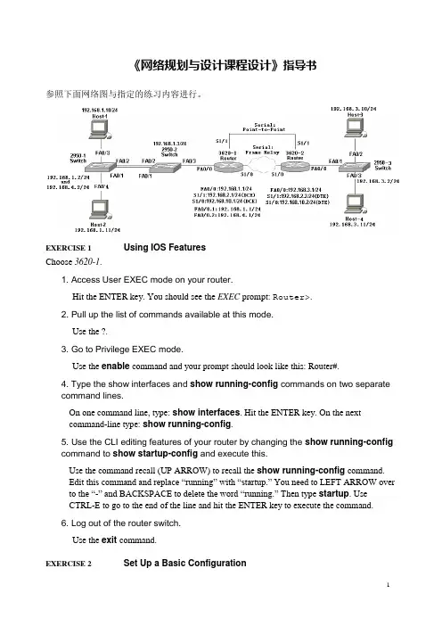
《网络规划与设计课程设计》指导书参照下面网络图与指定的练习内容进行。
EXERCISE 1 Using IOS FeaturesChoose 3620-1.1. Access User EXEC mode on your router.Hit the ENTER key. You should see the EXEC prompt: Router>.2. Pull up the list of commands available at this mode.Use the ?.3. Go to Privilege EXEC mode.Use the enable command and your prompt should look like this: Router#.4. Type the show interfaces and show running-config commands on two separatecommand lines.On one command line, type: show interfaces. Hit the ENTER key. On the nextcommand-line type: show running-config.5. Use the CLI editing features of your router by changing the show running-configcommand to show startup-config and execute this.Use the command recall (UP ARROW) to recall the show running-config command.Edit this command and replace “running” with “startup.” You need to LEFT ARROW over to the “-” and BACKSPACE to delete the word “running.” Then type startup. UseCTRL-E to go to the end of the line and hit the ENTER key to execute the command.6. Log out of the router switch.Use the exit command.EXERCISE 2 Set Up a Basic Configuration1. Starting with the 3620-1 router, go to Privilege EXEC mode and then enter Configuration mode.On 3620-1 router, access User EXEC mode and use enable to go to Privilege EXEC mode and then configure terminal to access Configuration mode.2. Assign a hostname of 3620-1.Use the hostname 3620-1 command and examine the prompt.3. Set a User EXEC password of cisco for telnet access.Enter the line vty 0 4 command and follow it with the login and password cisco commands.4. Exit this subcommand mode: exit.5. Assign an encrypted Privilege EXEC password of cisco.Enter enable secret cisco.6. Check whether or not the serial 1/0 interface is DTE or DCE.If it is DCE, assign a clock rate of 64000. Check the controller: show controller serial 1/0.7.if it’s the DCE, e nter the interface with configure terminal and interface serial 1/0. Configure the clock rate: clock rate 64000.8.Enable the fastethernet 0/0 interface: interface fastethernet 0/0,no shutdown, and exit.9.Enable the Serial 1/0 interface: interface Serial 1/0,no shutdown, and exit.10. Use a command to display all of the interfaces, their IP addresses, and their statuses on one screen and then show the details of fastethernet0 and serial 1/0 separately.Use the show interfaces command followed by show interface Fa0/0 and show interface s1/1.11. Save your configuration to NVRAM and view the active configuration.Save it with copy running-config startup-config and view it with showrunning-config.12.Configure the 3620-2 router.13. Assign a hostname of e the hostname 3620-2.Enter the line vty 0 4 command and follow it with the login and password cisco commands. Exit the subcommand mode: exit.14. Enter enable secret cisco.15. Enable the fastethernet 0/0 interface: interface fastethernet 0/0,no shutdown, and end. Check the serial 1/1 controller: show controller serial 1/1. if it’s the DCE, e nter the interface with configure terminal and interface serial 1/1. Configure the clock rate: clock rate 64000.ing: show interface. Make sure fa0/0 and s1/1 are “up and up”.17.Save your configuration to NVRAM and view the active configuration.Save it with copy running-config startup-config and view it with showrunning-config.18. Go to Configuration mode on your 2950-1 switch.Access User EXEC mode. Use enable to go to Privilege EXEC mode and then configure terminal to access Configuration mode. Assign a hostname of 2950 to the switch of e the hostname2950-1 command and examine the prompt. Enter the line vty 0 4 command and follow it with the login and password cisco commands.. Enter enable secret cisco. Exit the subcommand mode: end.19.View the switch’s interface status by using the show interface commands.20. Save your configuration to NVRAM and view the active configuration.Save it with copy running-config startup-config.21.Repeat this process(step 18 to 20)for the 2950-2 switch (with a hostname of 2950-2) and the 2950-3 switch (with a hostname of 2950-3).EXERCISE 3 Configuring the Switches1. Go to Configuration mode on your 2950-1 switch.2. Assign an IP address of 192.168.1.2/24 to the 2950-1 in VLAN 1, with a default gateway of 192.168.1.1.3.Enter the VLAN interface with interface vlan1. Next, enter the addressing information: ip address192.168.1.2 255.255.255.0.Enabled the interface: no shutdown. Exit the interface with the exit command and configure the default gateway: ip default-gateway 192.168.1.1.5. Save your configuration to NVRAM and view the configuration in NVRAM.Return to Privilege EXEC mode with the end command. Save it with copyrunning-config startup-config and view it with show startup-config.Host-1. On the CLI, type ipconfig /ip 192.168.1.10 255.255.255.0. Then, typeipconfig/dg 192.168.1.1(or winipcfg).Host-2. On the CLI, type ipconfig /ip 192.168.1.11 255.255.255.0. Then, typeipconfig/dg 192.168.1.1(or winipcfg).Test connectivity to Host-1: ping192.168.1.10. The ping should be successful6.Test connectivity to Host-2: ping192.168.1.11. The ping should be successful.7. Like above step, configure the 2950-2 switch ,parameter shows as topology .enter: enable, configure terminal, interface vlan1,ip address192.168.1.3255.255.255.0, no shutdown, exit, ip default-gateway192.168.1.1, end, copy running-config startup-config, and show startup-config. Make sure you configured the right hostname and IP address.8. Configure the 2950-3 switch ,parameter shows as topology .9. Test connectivity by pinging the Host-3 and Host-4 PCs: ping 192.168.3.10 and ping 192.168.3.11.The pings should be successful.EXERCISE 4 Configuring Trunks on Your Switches1. On the 2950-1 switch, set the trunk mode to on for the connection between the two 2950 switches and examine the status. Does the trunk come up?Choose 2950-1. Access Configuration mode: enable and configure terminal. Go into the interface: interface fa0/1. Set the trunk mode to trunk: switchport mode trunk. Exit configuration mode: end. Use the show interfaces trunk command to verify the status.You might have to wait a few seconds, but the trunk should come up. If one side is set to on, or desirable, and the other is set to on, desirable, or auto (default), then the trunk should come up.2. Save your configuration to NVRAM:copy running-config startup-config.3. On the 2950-2 switch, set the trunk mode to on for the connection between the two 2950 switches and verify the trunking status of the interface.Choose 2950-2. Access Configuration mode: enable and configure terminal. Go into the interface: interface fa0/1. Set the trunk mode to trunk: switchport mode trunk. Exit configuration mode: end. Use the show interfaces trunk command to verify the status.4. Save your configuration to NVRAM:copy running-config startup-config.EXERCISE 5 Configuring VLANs on Your Switches1. From the 2950-1, verify that you can ping Host-1 connected to fa0/3. Also ping Host-2 connected to 2950-1’s fa0/4 interface.Choose 2950-1. Access the CLI of the 2950-1. Execute ping 192.168.1.10and ping 192.168.1.11. Both should be successful.2. On the 2950-1, create VLAN 2. Then assign fa0/3 to VLAN 2 as an access-link port.Examine your VLANs.Access Configuration mode: enable and configure terminal. Use the vlan2 command to create your VLAN. Go into the interface: interface fa0/3. Assign the VLAN: switchport mode access, switchport access vlan2. Exit out of Configuration mode: exit and exit.3.View your VLANs on the 2950-1:show vlan. Make sure that all interfaces are inVLAN 1 except for fa0/3, which should be in VLAN 2.4. From Host-1, ping Host -2 (192.168.1.11) connected to the 2950-1 switch. Is theping successful?Choose Host-1. Execute ping192.168.1.11. The ping should fail, since the Host-2 is in VLAN 1, while Host-1 is in VLAN 2.5. On the 2950-1 switch, move Host-2 to VLAN 2 and verify your configuration.Choose 2950-1.: configure terminal and interface fa0/4. Assign the VLAN: switchport mode access, switchport access vlan2. Exit and Exit.6. View your VLANs: show vlan. Make sure that fa0/3 and fa0/4 are in VLAN 2..7. From Host-1, ping Host-2 (192.168.1.11), which is connected to the 2950-1 switch.Is the ping successful? Can Host-1 ping either the 2950-1 or the 2950-2 switch?Choose Host-1. Execute ping192.168.1.11. The ping should be successful, since all connections from Host-1 to Host-2 are in VLAN 2.Execute ping192.168.1.2and ping 192.168.1.3. Both should fail, since both of these switches, by default, are in VLAN 1 and the hosts are in VLAN 2.EXERCISE 6 Manipulating Your Ro uter’s Configuration Files1. Access the 2600 router’s Privilege EXEC mode and save your router’s activeconfiguration to NVRAM. Verify the copy.Access Privilege EXEC mode: enable. Use the copy running-config startup-configcommand. Verify the copy: show startup-config.2. Change the hostname on the router to different and then reload the savedconfiguration from the NVRAM into RAM. What is the hostname?Access Configuration mode (configure terminal) and use the hostname differentcommand to change the rou ter’s name to different. Exit Configuration mode: end. Restore your configuration with copy startup-config running-config. Your prompt shouldchange back to the previous name of the router (you might have to wait a few seconds forthis to complete).3. Era se your router’s configuration in NVRAM. Examine the configuration file inNVRAM. Save the active configuration file to NVRAM. Examine the configuration file in NVRAM.Use the erase startup-config command to erase your configuration in NVRAM. Use the show startup-config command to verify the configuration file was deleted. Use the copy running-config startup-config command to save your configuration to NVRAM. Use the show startup-config command to verify that your router’s configuration was backed up from RAM to NVRAM.EXERCISE 7 Using the Router’s Troubleshooting Tools1. Access the 3620-1 router in the simulator. See what neighbors are directly connected to the router. What is the IP address of the 3620-2 router?Choose 3620-1. Use show cdp neighbors command to view the 3620-1’sneighbors—you may have to wait 60 seconds to see neighbors from this interface. You should see one of the 2950 switches and the 3620-2 router. Use the show cdp neighbors detail command to view the 3620-2’s address: it is 192.168.2.2.2. Access the 2950-2 switch in the simulator. See what neighbors are directly connected to the router. Which neighbors do you see? What are their IP addresses?At the top of the simulator in the menu bar, click on the eSwitches icon and choose 2950-2.Use the show cdp neighbors command to view your neighbors. You should see the 2950-1 switch and 3620-1 router. Add the detail parameter to the preceding command to see their IP addresses.EXERCISE 8 Static Route Configuration1. On the 3620-1, verify that the fa0/0 and s1/1 interfaces are up. If not, bring them up. Examine the IP addresses configured on the 3620-1.Use the show interfaces command to verify your configuration. If fa0/0 and s1/1 are not up, go into the interfaces (fa0/0 and s1/1) and enable them: no shutdown. Use the show interfaces command to verify that the IP addresses you configured are still there.2.Examine the routing table on the 3620-1.Use the show ip route command. You should have two connected networks: 192.168.1.0 connected to fa0/0 and 192.168.2.0 connected to s1/1.3. On the 3620-2, verify that the fa0/0 and s1/1 interfaces are up. If not, bring them up. Examine the IP addresses configured on the 3620-2 and look at its routing table.Use the show interfaces command to verify your configuration. If fa0/0 and s1/1 are not up, go into the interfaces (fa0/0 and s1/1) and enable them: no shutdown. Use the show interfaces command to verify that the IP addresses you configured are still there.4.Examine the routing table on the 3620-2.Use the show ip route command. You should have two connected networks: 192.168.3.0 connected to fa0/0 and 192.168.2.0 connected to s1/1.3. Test connectivity between Host-1 and the 3620-1.From Host-1,ping the 3620-1:ping192.168.1.1. The ping should be successful.If it is not, then you may have used the configuration from the VLAN lab and have a VLANconfiguration problem.4. Test connectivity between Host-3 and the 3620-2.From Host-3,ping the 3620-2:ping192.168.3.1. The ping should be successful.5. Test connectivity between Host-3 and the Host-1.From Host-3,ping the Host-1:ping192.168.1.10. The ping should fail: there is no route from the 3620-2 to this destination.6.Look at the 3620-2’s routing table: show ip route. I t doesn’t list 192.168.1.0/24.7. On the 3620-2, configure a static route to 192.168.1.0/24, which is connected to the 3620-1.Choose 3620-2. Configure the static route:ip route 192.168.1.0 255.255.255.0 192.168.2.1. View the static route: show ip route. Make sure that 192.168.1.0/24 shows up in the routing table as a static route (S).8. On the 3620-1, configure a static route to 192.168.3.0/24, which is connected to the 3620-2. View the routing table.Choose 3620-1. Configure the static route:ip route 192.168.3.0 255.255.255.0 192.168.2.2 and end.View the static route: show ip route. Make sure that 192.168.3.0/24 shows up in the routing table as a static route (S).9. From Host-3, ping the fa0/0 interface of the 3620-1.Choose Host-3. Access Host-3 and ping the fa0/0 interface of the 3620-1 router:ping 192.168.1.1. The ping should be successful. Ping Host-1 ping 192.168.1.10. The ping should be successful.10. From Host-3, ping Host-1.Choose Host-3: ping 192.168.1.10. The ping should be successful.EXERCISE 9 Basic IP and Routing Troubleshooting1. Test connectivity from Host-1 to Host-3.On Host-1, ping Host-3: ping 192.168.3.10. Note that the ping fails.2. Examine the IP configuration on Host-1.Execute winipcfg. Make sure the IP addressing information is correct: IP address of 192.168.1.10,subnet mask of 255.255.255.0, and default gateway address of 192.168.1.1. 3. Test connectivity from Host-1 to its default gateway.Ping the default gateway address: ping192.168.1.1. The ping should be successful, indicating that at least layer 3 is functioning between Host-1 and the 2600.4. Verify Host-3’s IP configuration.Execute winipcfg. Make sure the IP addressing information is correct: IP address of 192.168.3.10,subnet mask of 255.255.255.0, and default gateway address of 192.168.3.1. 5. Test connectivity from Host-3 to its default gateway.At the Host-3. ping192.168.3.1. The ping should still fail, indicating that there is a problem between Host-3 and the 3620-2. In this sample, assume layer 2 is functioning correctly; therefore, it must be a problem with the 3620-2.6. Check the 3620-2’s IP configuration.From the 3620-2,ping Host-3: ping192.168.3.10. The ping should still fail. Examine the interface on the 3620-2:show interface fa0/0.The interface is disabled, but it has the correct IP address: 192.168.3.1.7.Access Host-1 and retry pinging Host-3.From the Host-1,ping Host-3: ping192.168.3.10. The ping should still fail. So far,there is connectivity within 192.168.1.0 and 192.168.3.0,but there is still a problem between these two networks.8. Check the interface statuses on the 3620-1 and verify connectivity to the 3620-2. On 3620-1:show ip interface brief. Notice that the fa0/0 and s1/1 are both up.Try pinging the 3620-2’s s1/1 interface: ping192.168.2.2. The ping fails. Examine CDP information that the 3620-1 has learned about the 3620-2:show cdp entry 3620-2.Notice that the 3620-2 has no IP address.9. Fix the IP addressing problem on the 3620-2 and retest connectivity across the serial connection.At 3620-2. Fix the IP address: configure terminal, interface serial 1/1, ip address 192.168.2.2 255.255.255.0, end. Retest the connection to the 3620-1: ping192.168.2.1. The ping should be successful.10. Examine the routing table on the 3620-2 and verify that 192.1681.0/24 shows up as a static route.Examine the routing table: show ip route. As you can see, 192.168.1.0 shows up as a static route and points to 192.168.2.1.11. Access Host-3 and try connectivity between its default gateway and the 3620-1 router.At the Host-3. Test the connection to the 3620-2: ping192.168.3.1.The ping should be successful, considering that we already tested it.Test connectivity to the 3620-1: ping 192.168.2.1. The ping should fail. This presents an interesting problem. Host-1 can ping the 3620-1. The 3620-1 can ping the 3620-2. Host-3 can ping the 3620-2.So, on a hop-by-hop basis, you have IP connectivity. The 3620-2 can even ping Host-1, indicating that some routing functioning is working.12. Access the 3620-1 router and examine its routing table. Fix the problem.Choose 3620-1. Examine the routing table: show ip route. Does the 3620-1 know how to reach 192.168.3.0/24?It does not. The 3620-2 router could ping Host-1 since the 3620-1 router is directly connected to these segments; but any traffic from the 3620-1 to 192.168.3.0/24 will fail since the router doesn’t have a path. Add a static route to 192.168.3.0/24: ip route192.168.3.0 255.255.255.0192.168.2.2. Test connectivity to Host-3: ping 192.168.3.10. The ping should be successful.13. Now test connectivity between Host-1 and Host-3.At Host-1. Test connectivity to Host-3: ping192.168.3.10. The ping should be successful.EXERCISE 13 Configuring RIP1. On the 3620-1, verify that the fa0/0 and s1/1 interfaces are up. If not, bring them up. Examine the IP addresses configured on the 3620-1 and look at its routing table.At the 3620-1, use the show interfaces command to verify your configuration. If fa0/0 and s1/1 are not up, go into the interfaces (fa0/0 and s1/1) and enable them: configure terminal, interface type [slot_#/]port_#, no shutdown, and end.2. Use the show ip interfaces brief command to verify that the IP addresses you configured are still there.3. Use the show ip route command. You should have two connected networks: 192.168.1.0 connected to fa0/0 and 192.168.2.0 connected to s1/1.4. On the 3620-2, verify that the fa0/0 and s1/1 interfaces are up. If not, bring them up.5. Examine the IP addresses configured on the 3620-2. Use the show ip interfaces brief command to verify that the IP addresses you configured before are still there.6. On the 3620-2, use the show ip route command. You should have two connected networks: 192.168.3.0 connected to fa0/0 and 192.168.2.0 connected to s1/1.7. Test connectivity between Host-1 and the 3620-1.From Host-1, ping the 3620-1 router (the default gateway): ping 192.168.1.1. The ping should be successful.8. Test connectivity between Host-3 and the 3620-2. Test connectivity between Host-3 and Host-1.From the Host-3,ping the 3620-2 router (the default gateway): ping192.168.3.1. The ping should be successful.9. From the Host-3, ping Host-1: ping192.168.1.10.The ping should fail. Why? there is no route from the 3620-2 to this destination.(Look at the 3620-2’s routing table: it doesn’t list 192.168.1.0/24.)10. Access the 3620-2 and examine the routing table to see why the ping failed.At the 3620-2. Examine the routing table: show ip route. Notice that it doesn’t list 192.168.1.0/24, which explains why Host-3 can’t reach Host-1.11. Enable RIPv1 on the 3620-1 router.On the 3620-1, execute the following: router rip, network192.168.1.0, and network 192.168.2.0.12. Enable RIPv1 on the 3620-2 router.On the 3620-2, execute the following: router rip, network192.168.2.0, and network 192.168.3.0.13. On the 3620-1, verify the operation of RIP.At the top of the simulator in the menu bar, click on the eRouters icon and choose 3620-1. Use the show ip protocols command to make sure that RIP is configured—check for the neighbo ring router’s IP address. Use the show ip route command and look for the remote LAN network number as a RIP (R) entry in the routing table. On the 3620-1, you should see 192.168.3.0, which was learned from the 3620-2.14. On the 3620-2, verify the operation of RIP.At the top of the simulator in the menu bar, click on the eRouters icon and choose 3620-2. Use the show ip protocols command to make sure that RIP is configured—check for the neighboring router’s IP address. Use the show ip route command and look for the remote LAN network number as a RIP (R) entry in the routing table. On the 3620-2, you should see 192.168.1.0, which was learned from the 3620-1.15. On Host-1, test connectivity to Host-3.At the top of the simulator in the menu bar, click on the eStations icon and choose Host-1. On Host-1, test connectivity: ping192.168.3.10. The ping should be successful.EXERCISE 14 Basic RIP Troubleshooting1. Test connectivity from Host-1 to Host-3 with ping as well as from Host-1 to its default gateway.At the top of the simulator in the menu bar, click on the eStations icon and choose Host-1.On Host-1, ping Host-3: ping192.168.3.10. Note that the ping fails.2. Examine the IP configuration on Host-1 by executing: winipcfg.Make sure the IP addressing information is correct: IP address of 192.168.1.10,subnet mask of 255.255.255.0, and default gateway address of 192.168.1.1.3. On Host-1, ping the default gateway address: ping192.168.1.1. The ping should fail, indicating that at least layer-3 is not functioning between Host-1 and the 3620-1.4. Check the 3620-1’s IP configuration.At the top of the simulator in the menu bar, click on the eRouters icon and choose 3620-1.From the 3620-1, ping Host-1: ping192.168.1.10. The ping should fail. Examine the interface on the 3620-1: show inte r face fa0/0.The interface is enabled, but has an incorrect IP address: 192.168.11.1. Fix the IP address: configure terminal, interface fa0/0, ip address192.168.1.1255.255.255.0, end. Verify the IP address: show interface fa0/0.5. Retry the ping test: ping192.168.1.10. The ping should be successful. Save the configuration on the router: copy running-config startup-config.6. Test connectivity from Host-1 to Host-3 with ping.At the top of the simulator in the menu bar, click on the eStations icon and choose Host-1.On Host-1, ping Host-3: ping192.168.3.2. Note that the ping still fails.7. Examine Host-3’s IP configration.At the top of the simulator in the menu bar, click on the eStations icon and choose Host-3.Examine the IP configuration on Host-3 by executing: winipcfg. Make sure the IP addressing information is correct: IP address of 192.168.3.10,subnet mask of 255.255.255.0, and default gateway address of 192.168.3.1.8. On Host-3 ping the default gateway address: ping192.168.3.1. The ping should be fail, indicating that there is a problem between Host-3 and the 3620-2. In this example, assume layer-2 is functioning correctly; therefore, it must be a problem with the 3620-2.9. Check the interface statuses and IP configuration on the 3620-2 and verify connectivity to the 3620-1. Also verify RIP’s configuration.At the top of the simulator in the menu bar, click on the eRouters icon and choose 3620-2.Check the status of the interfaces: show interfaces. Notice that the fa0/0 is disabled, but s1/0 is enabled (up and up). Go into fa0/0 and enable it: configure terminal, interface fa0/0, no shutdown, end. Verify the status of the fa0/0 interface: show interface fa0/0.10. Test connectivity from 3620-2 to 3620-1 with ping.Try pinging Host-3:ping192.168.3.10. The ping should succeed. Try pinging the 3620-1’sserial 1/1 interface: ping192.168.2.1. The ping succeeds.11. Verify RIP’s configuration on 3620-2.Examine the 3620-2’s RIP configuration: show ip protocol. You should see RIP as the routing protocol and networks 192.168.2.0 and 192.168.3.0 included. From this output, it looks like RIP is configured correctly on the 3620-2. Save the configuration on the router: copy running-config startup-config.12. Test connectivity from the 3620-2 to Host-1. Examine the routing table.Test the connection to Host-1: ping192.168.1.10. The ping should fail. This indicates a layer-3 problem between the 3620-2 and Host-1.13. Examine the 3620-2’s routing table: show ip route. Notice that there are only two connected routes (192.168.2.0/24 and 192.168.1.0/24), but no RIP routes.14. Access the 3620-1 router and examine RIP’s configuration.Choose 3620-1, examine the routing table: show ip protocol. What networks are advertised by the 3620-1? You should see 192.168.1.0 and 192.168.11.0. Obviously, serial 1/1’s interface isn’t included since 192.168.2.0 is not configured.15. Fix the problem with the 3620-1’s RIP configuration.Fix this configuration problem:: configure terminal, router rip, no network 192.168.11.0, network192.168.1.0, end. examine the routing table: show ip protocol.16. Test connectivity to Host-3: ping192.168.3.10.The ping should be successful. Save the configuration on the router: copy running-config startup-config.17. Now test connectivity between Host-1 and Host-3.At the top of the simulator in the menu bar, click on the eStations icon and choose Host-1.Test connectivity to Host-3: ping192.168.3.10. The ping should be successful.EXERCISE 15 Configuring OSPF1. On the 3620-1, verify that the fa0/0 and s1/1 interfaces are up. If not, bring them up. Examine the IP addresses configured on the 3620-1 and look at its routing table.At the top of the simulator in the menu bar, click on the eRouters icon and choose 3620-1.On the 3620-1, use the show interfaces command to verify your configuration. If fa0/0 and s1/1 are not up, go into the interfaces (fa0/0 and s1/1) and enable them: configure terminal, interface type port, no shutdown, end, show interfaces. Use the show ip route command. You should have two connected networks: 192.168.1.0 connected to fa0/0 and 192.168.2.0 connected to s1/1.2. On the 3620-2, verify that the fa0/0 and s1/1 interfaces are up. If not, bring them up. Examine the IP addresses configured on the 3620-2 and look at its routing table.At the top of the simulator in the menu bar, click on the eRouters icon and choose 3620-2. On the 3620-2, verify that the fa0/0 and s1/1 interfaces are up. If not, bring them up: configure terminal, interface type port, no shutdown, end, show interfaces. Use the show interfaces command to verify that the IP addresses you configured are still there. Use the show ip route command. You should have two connected networks: 192.168.3.0 connected to fa0/0 and 192.168.2.0 connected to s1/1.3. Test connectivity between Host-1 and the 3620-1.At the top of the simulator in the menu bar, click on the eStations icon and choose Host-1. From Host-1, ping the 3620-1: ping192.168.1.1. The ping should be successful.4. Test connectivity between Host-3 and the 3620-2.At the top of the simulator in the menu bar, click on the eStations icon and choose Host-3. From Host-3, ping the 3620-2 router: ping192.168.3.1. The ping should be successful. 5. From Host-3, ping Host 1:ping192.168.1.10. The ping should fail: there is no route from the 3620-2 to this destination (look at the 3620-2’s routing table: it doesn’t list 192.168.1.0/24).6. Enable OSPF on the 3620-1 and 3620-2 routers, using a process ID of 1, and put all interfaces in area 0.At the top of the simulator in the menu bar, click on the eRouters icon and choose 3620-1. On the 3620-1 router, configure the following: configure terminal, router ospf1, network0.0.0.0 255.255.255.255 area 0, end. At the top of the simulator in the menu bar, click on the eRouters icon and choose 3620-1.7.On the 3620-2 router, configure the following: configure terminal, router ospf 1,network 0.0.0.0 255.255.255.255 area 0, end.8. On the 3620-2, verify the operation of OSPF. Is either router a DR or BDR on the WAN link?At the top of the simulator in the menu bar, click on the eRouters icon and choose 3620-2. Use the show ip protocols command to make sure that OSPF is configured—check for the neighboring router’s update. Use the show ip route command and look for the remote LAN network number as a RIP (O) entry in the routing table. Use the show ip ospf neighbor command to view your neighboring router. Neither should be a DR or BDR on the serial link, since point-to-point connectio ns don’t use DRs and BDRs.9. On the 3620-1, verify the operation of OSPF.At the top of the simulator in the menu bar, click on the eRouters icon and choose 3620-1. Use the show ip protocols command to make sure that OSPF is configured—check for the neig hboring router’s update. Use the show ip route command and look for the remote。
网络规划与设计第二版课程设计 (2)

网络规划与设计第二版课程设计一、课程简介《网络规划与设计第二版》是一门旨在教授学生网络规划、设计、实施和维护的专业课程。
本课程注重理论与实践相结合,旨在为学生提供全面的网络知识和技能,使其能够设计、实现、管理和维护企业网络,以满足企业对网络技术的要求。
二、课程目标本课程的主要目的是培养学生以下几方面的能力: 1. 掌握企业网络规划、设计、实施和维护的基本原理和方法。
2. 熟悉企业网络中主要的硬件设备及其功能,并能够熟练地选择和配置这些设备。
3. 熟悉企业网络中主要的软件应用及其功能,并能够熟练地配置和运行这些应用。
4. 掌握网络安全的基本知识和技能,并能够及时识别和处理网络安全问题。
三、课程内容1. 企业网络规划和设计基础•企业网络规划和设计的基本概念和原则•企业网络规划和设计的流程和步骤•企业网络中的拓扑结构•企业网络中的网络协议2. 企业网络硬件设备•企业网络中的路由器和交换机•企业网络中的集线器和网桥•企业网络中的防火墙和入侵检测设备3. 企业网络软件应用•企业网络中的网络操作系统•企业网络中的数据库管理系统•企业网络中的应用软件4. 网络安全•网络安全的概念和原则•网络安全的威胁和攻击方式•网络安全的防御措施四、课程方法本课程以理论为基础,实践为重点。
除了传授理论知识之外,还将通过实验、案例分析和课程设计等方式加强学生的实践能力。
具体的教学方法包括: 1. 讲解理论知识,培养学生的网络思维和理解能力。
2. 演示操作过程和结果,帮助学生熟悉网络工具的操作方法和实际应用。
3. 设计功能完善的课程实验,让学生动手操作并解决实际问题。
4. 开展课程设计,使学生通过实际操作设计出符合企业实际需求的网络方案。
五、课程评估课程评估主要包括两个方面的内容: 1. 日常表现:包括参与度、课堂表现、作业完成情况等。
2. 课程设计:学生将通过课程设计,设计一个符合实际企业需求的网络方案,并通过评审得出成绩。
《网络规划与设计》课件

IP地址的分类与分配
B类地址
最高两位为10,用 于中等规模的网络 。
D类地址
最高位为1110,用 于组播。
A类地址
最高位为0,用于大 型网络和机构。
C类地址
最高三位为110,用 于小型网络和主机 。
E类地址
最高位为11110, 用于实验和研究。
子网划分与CIDR表示法
子网划分
通过将IP地址的主机部分划分为更小 的网络段,实现更精细的网络控制和 管理。
防火墙配置
配置防火墙的访问控制列表、安全策略等参数,实现网络安全防护和流量过滤。
06
网络性能优化
QoS技术及应用
QoS技术
QoS,即服务质量,是一种网络服务性能的综合评价指标。它涉及到数据传输的可靠性、速度以及数 据包丢失率等多个方面。
应用场景
在实时音视频传输、大型多人在线游戏、金融交易等对网络服务质量要求较高的场景中,QoS技术显 得尤为重要。
网络规划的基本原则
01
02
03
04
需求导向
根据实际需求进行规划,确保 网络能够满足用户和企业的发
展需要。
先进性
采用先进的技术和设备,确保 网络具有较高的性能和可靠性
。
经济性
合理控制成本,实现经济效益 最大化。
可扩展性
考虑未来的扩展需求,确保网 络具有良好的扩展性和灵活性
。
网络规划的步骤
网络拓扑设计
性能优化规划
根据网络流量特点,优化网络 设备参数,提高网络性能和响 应速度。
02
网络需求分析
用户需求分析
01
02
03
用户数量
分析目标网络的用户数量 ,包括员工、客户和合作 伙伴等。
《网络规划与设计》课件
线性拓扑结构的设计
线性拓扑结构是一种简单的网络布局,适用于小型组织或分支机构。
环形拓扑结构的设计
环形拓扑结构是一种将各个设备连接成环状的网络布局,适用于相对较小的 网络。
树形拓扑结构的设计
树形拓扑结构是一种层次化的网络布局,适用于大型企业或组织。
网状拓扑结构的设计
网状拓扑结构是一种将各个设备直接相连形成密集连接的网络布局,适用于高度可靠性要求的网络。
网络规划与设计的步骤
1
拓扑设计
2
选择适合的网络拓扑结构,如线性、环
形、树形或网状。
3
IP地址规划
4
规划和分配IP地址,确保网络中的每个设
备都能正常通信。
5
需求分析
了解业务需求,确定网络设计的目标和 范围。
硬件选型
选择合适的网络设备和技术,如交换机、 路由器、防火墙等。
安全设计
确定安全策略、防火墙规则以及其他安 全措施,保护网络免受外部威胁。
网络规划与设计是指设计和规划企业或组织中网络的架构、拓扑结构、协议 选择等,以满足业务需求并提供可靠的网络连接。
网络规划与设计的重要性
1 提高效率
一个合理规划和设计的网络可以提高数据传输的速度,提升员工工作效率。
2 增强安全性
通过规划合适的网络安全措施,可以降低网络遭受攻击的风险。
3 节约成本
通过网络规划和设计,可以避免不必要的硬件和软件浪费,从而节约成本。
《网络规划与设计》PPT 课件
这个PPT课件将介绍网络规划与设计的重要性、步骤以及各种拓扑结构的设计, 并探讨局域网、城域网、广域网、云计算网络和无线网络等的设计,以及IPv4、 IPv6、网络协议、网络安全、网络负载均衡等。还将讲解流量监测与分析、防 火墙、数据中心网络,最后讲解故障排除与优化。
网络规划与设计课程设计报告
网络规划与设计课程设计课程名称网络规划与设计题目名称企业(园区)网络规划设计专业班级 17网工6班学号 08、24、26、32、40、51学生姓名指导老师易辉艳设计时间 2020/10/26-2020/10/30一、设计背景概述在今天竞争激烈的市场环境下,许多中小型企业都在追求高效的管理与沟通方法,发展跨地区、跨国业务,促进客户服务,增强企业的市场竞争力。
特别在当今信息化的现代社会,企业的运作模式也发生了根本性变化。
建设企业网络来提高企业运作效率的做法越来越普及。
所以近年来,许多中小型企业都建立了自己的网络,但是,由于许多中小企业的决策者对网络的应用和管理,在认识上存有一定的局限,以及受到现有企业条件和信息技术力量的局限,往往会在用网,尤其是在如可管理好企业的网络、挖掘和整合企业网络资源优势、为企业发展核心业务服等诸多方面,还存有许多不尽如入意的地方,致使不少中小企业的网络系统,从建立网络,到应用网络,直至管理网络,都缺乏一个科学性、有序化和规范化的发展态势,甚至直接影响乃至制约着企业核心业务的持续发展。
所以一个良好的中小型网络成为了企业发展好坏的决定因素。
二、需求分析2.1 设计需求根据中小型企业网络的含义、特点,按照标准的网络规划和组网技术来设计一个功能完善的企业园区网络,使用Cisco模拟器对网络进行比较完善的模拟,以实现各个部门之间的互联和控制,需用各种成熟的路由技术对各层进行设计配置。
2.2 需求表设备需求表:技术需求:三、逻辑设计3.1 拓扑设计3.2 IP地址规划Vlan规划(表格)一、物理设计实现具体配置过程四、测试1.PC机ip地址自动获取2.PC0pingdhcp服务器:3.PC0pingWeb服务器4.PC0pingDNS服务器5.PC2pingDHCP服务器6.PC2pingWeb服务器7.PC2pingDNS服务器8.PC0浏览web9.PC0浏览DNS服务器web10.PC0浏览DNS域名11.PC0ping外网Route012.网络设备信息的获取和修改1.在PC桌面使用管理软件MIB Browser.2.设置被管理设备的IP及读写团体密码。
16级《网络工程与设计课程设计》实验指导书(2018-2019-2)
分为4个大实验,也就是每个小组交4份实验报告实验1设备管理配置(包含下面目录中的1和2的实验内容)实验2网络管理协议的使用(包含下面目录中的3和4的实验内容)实验3小型网络的组建和管理(包含下面目录中的5的实验内容)实验4 简单企业网络的组建和管理(包含下面目录中的6的实验内容)目录1 管理设备配置 (1)2 策略路由配置 (3)3 PPP协议的使用 (3)4 Cisco VTP协议的使用 (3)5 小型网络综合配置 (6)6 企业网络综合配置 (8)1 管理设备配置一、实验设备1台交换机,1台路由器,一台服务器,两根直连线。
(在Packet Tracer中完成)二、实验要求本实验将在 Cisco 路由器上配置常用设置,将配置保存到 TFTP 服务器,然后从 TFTP 服务器恢复配置。
地址表:Router1 fa0/0 192.168.1.1 255.255.255.0Server-PT fa 192.168.1.2 255.255.255.0三、实验步骤步骤 1:配置 ROUTER1的端口fa0/0的IP地址步骤 2:配置 TFTP 服务器的IP地址IP 地址:192.168.1.2子网掩码:255.255.255.0默认网关:192.168.1.1步骤 3:验证连通性从 ROUTER1 Ping TFTP 服务器,看它们是否能正常通信。
步骤 4:备份启动配置到 TFTP 服务器在 ROUTER1 上使用 copy running-config tftp 命令。
输入 TFTP IP 地址作为远程主机的地址;保留所有其它问题为默认值(按 Enter)步骤 5:验证步骤 4成功。
单击 TFTP 服务器。
接着单击 Config(配置)选项卡。
然后单击 TFTP 选项卡。
确认列出了 ROUTER-confg 文件(应位于列表底部)步骤 6:把步骤 4备份的配置文件恢复到路由器的startup-config 中在 ROUTER1 上使用 copy tftp startup-config命令。
网络规划与设计课程设计
• 网络规划
– 通过了解用户建设网络应用的目的,从网 络工程建设的可行性、可靠性、可管理性 和扩展性等方面给出需求分析计划书。 – 包括:应用背景、业务需求、网络管理、 网络安全以及升级与扩展等方面。
• 网络设计
– 逻辑设计:给出网络的拓扑图、地址分配以 及路由算法的选择等。 – 物理设计:选定物理设备和传输介质,设计 综合布线系统。
网络规划与设计课程设计
课程目的
• 结合网络工程经典案例进行规划和设计, 达到学以致用 • 针对网络规划设计师考试真题进行讲解
课程安排
• 网络工程经典案例
– 涉及的网络基础知识讲解 – 网络实践案例分析
• 网络规划设计师考试题目讲解
为什么要进行网络规划与设计
• 网络工程是研究网络系统的规划、设 计与管理的工程科学。 • 网络工程建设的过程
ቤተ መጻሕፍቲ ባይዱ
• 网络实施
– 制定工程实施计划,按计划进行施工,并进 行测试验收。 – 注意:对于大型的网络,在施工之前需要 注意:对于大型的网络, 进行仿真测试。 进行仿真测试。
• 网络的运行和维护