PASAN太阳模拟器测试仪
太阳模拟器下的温度系数测试_

背板的温度极差分布情况。
“四点测温”代表样品温度是由图 2 所示的 4 个热电
偶所测温度的平均值来表示的,即按新版温度系数
5
4.5
第 1 次测试
测试对温度的要求进行处理。
4
第 2 次测试
比较表 2 中“单点测温”和“四点测温”所得
第 3 次测试
3.5
到的两组温度系数,可以看出,两组数据的一致性
温度极差 /℃
10
10
8
8
6
6
电流 /A 电流 /A
4
4
2
2
0 0 10 20 30 40
电压 /V
0 0 10 20 30 40
电压 /V
(a) 位置调整前 (b) 位置调整后 图 3 测组件在稳态模拟器下的 I-V 曲线
从表 1 中相对标准差来看,电流温度系数 α 的 波动很大,为 33.875%,β 和 γ 相对较小。这一方面 是由于电流温度系数 α 本身的绝对值较小,容易导 致较大的相对误差。另一方面,硅太阳能电池的短 路电流与光强呈线性关系。测试过程中虽然对样品 的位置进行了调整,但不可能大幅改变样品表面光 的辐照不均匀性和不稳定度(整个测试期间,监测 点光强在 1 049 ~ 1 115 W/m2 之间波动),加上样品
第3次
0.063%
0.052%
52%
0.053%
-0.336%
-0.340%
-0.336%
-0.326%
-0.342%
-0.334%
-0.438%
-0.444%
-0.439%
-0.425%
-0.448%
-0.436%
平均值 0.056% 0.056% -0.337% -0.334% -0.440% -0.436%
大辐照面AM0太阳模拟器检测

i r r a di a n c e s ur f a c e c omb i ne d wi t h ma t ur e d t e s t i n g e xp e r i e nc e s t h e s e y e a r s . The s t ud y a c hi e v e me nt s ha v e
D 0 I : 1 0 . 3 9 6 9 / j . i s s n . 1 0 0 1 —2 3 2 】 【 . 2 0 1 3 . 0 4 . 1 9
T h e t e s t i n g o f AMO s o l a r s i mu l a t o r w i t h l a r g e i r r a d i a n c e s u r f a c e . G u Li s h a n ( C h a n c h u n I n s t i t u t e o f O p — t i c s ,F i n e Me c h a n i c s a n d P h y s i c s , C h i n e s e Ac a d e my o f S c i e n c e s Po s t c o d e , C h a n g c h u n 1 3 0 0 3 3 , C h i n a )
c a n s o l a r s i mu l a t i o n s t a n d a r d t o d e v e l o p t h e s t u d y a b o u t t h e t e s t i n g me t h o d o f s o l a r s i mu l a t o r wi t h l a r g e
太阳模拟器介绍

太阳模拟器这里主要解释光伏产业用太阳模拟器.太阳模拟器是用来模拟太阳光的设备,在光伏领域里,再配以电子负载,数据采集和计算等设备,可以用来测试光伏器件(包括太阳电池片,太阳电池组件等)的电性能,如Pmax, Imax, Vmax,Isc,Voc,FF,Eff, Rs, Rsh以及I-V曲线等.这些参数不仅能够从一定程度上反应出电池的性能,也关系到电池最后出厂的等级和价格.因此,一台可靠的太阳模拟器,不仅对生产工艺有参考意义,更关系到产品的品质和制造厂商的利润和信誉.对于光伏性能测试,可用的商业化太阳模拟器有两类,一类是稳态模拟器(例如滤光氙灯,双色滤光钨灯-ELH灯或改进的汞灯),这类模拟器适用于单体电池和小尺寸组件的测试.另一类是脉冲模拟器,由一个或者两个长弧氙灯组成,这类模拟器由于在大面积范围内辐射度均匀性好,能够更好地适应于大尺寸组件的测试.这类模拟器的另外一个优点是,被测电池热输入可以忽略,这样在测试时被测点出与环境测试温度保持一致,而环境温度是可以很容易精确测量的.脉冲发生网络,数据采集和处理系统通常做为模拟器的部件提供.一.模拟器要求1.总辐照度模拟器必须能够在测试平面上达到1000W/平方米的标准辐照度(用标准电池测量),并根据需要可对辐照度在标准辐照度值上下进行一定的调节.2.光谱匹配模拟器光谱辐照度分布应与标准光谱辐照度分布匹配.等级A的匹配度在0.75~1.25,等级B的匹配度在0.6~1.4,等级C的匹配度在0.4~2.03.均匀度在测试平面上,指定测试区域内的辐照度应该达到一定的均匀度,辐照度用合适的探测器量测.等级A的辐照均匀度<=+/-2%,等级B的辐照均匀度<=+/-5%,等级C的辐照均匀度<=+/-10%.对于单体电池和电池串的测试,探测器最大尺寸应小于电池最小尺寸的一半.对于组件,探测器尺寸应不大于组件中单体电池的尺寸.不均匀度=+/-((最大幅照度-最小辐照度)/(最大幅照度+最小辐照度))*100%其中,最大辐照度和最小辐照度是指在指定范围内探测器在任意指定点的测量值.4.辐照稳定度数据采集期间,辐照度应该具有一定的稳定度.等级A的稳定度在<=+/-2%,等级B 的稳定度在<=+/-5%,等级C的稳定度在<=+/-10%,辐照不稳定度=+/-((最大幅照度-最小辐照度)/(最大幅照度+最小辐照度))*100% 其中,最大辐照度和最小辐照度是数据采集期间在测试平面内探测器在任意指定点的测量值.具体的测试方法请参考IEC 60904-9.二.市场概况PASAN,SPIRE和BERGE的大面积太阳模拟器目前是国际上被广泛认可的.在稳定性和一致性上有较强的优势.但是百万级的价格却是国内用户很难接受的.再加上昂贵的售后服务费用,他们的设备并没有成为国内电池制造厂商的主力.鉴于国内的状况,国内的不少科研单位和大学也一直致力于太阳模拟器的研究开发.主要代表是西安交通大学的陕西众森电能科技有限公司和上海交通大学太阳能研究所的上海赫爽太阳能科技有限公司。
太阳能系统测试仪 CE CAT II 1000V CAT III 300V说明书
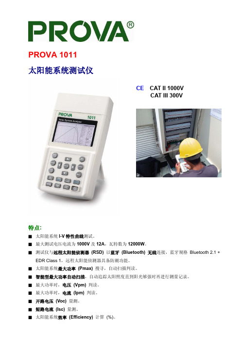
PROVA 1011太阳能系统测试仪CE CAT II 1000VCAT III 300V特点:■ 太阳能系统I-V特性曲线测试。
■ 最大测试电压电流为1000V及12A,瓦特数为12000W。
■ 测试仪与远程太阳能侦测器 (RSD)以蓝牙 (Bluetooth) 无线连接,蓝牙规格Bluetooth 2.1 + EDR Class 1,远程太阳能侦测器具备防潮功能。
■ 太阳能系统最大功率 (Pmax)搜寻,自动扫描判读。
■ 智能型最大功率自动扫描,自动追踪太阳照度直到阳光够强时再进行测量记录。
■ 最大功率时,电压 (Vpm)判读。
■ 最大功率时,电流 (Ipm) 判读。
■ 开路电压 (Voc)量测。
■ 短路电流 (Isc) 量测。
■ 太阳能系统效率 (Efficiency)计算 (%)。
■ 太阳能板温度、照度 (Irradiance) 及串联电阻 (Rs)量测。
■ I-V特性曲线具光标功能(能移动光标,以判读所在位置的电压、电流、瓦特等读值)。
■ 具有数据记录/开启功能,可定时分析记录太阳能系统特性曲线。
■ 根据IEC规定转换标准环境 (STC) I-V曲线及参数显示。
■ 标准环境 (STC) 测试报告与工作环境 (OPC) 测试报告,判断太阳能板OK/NO OK。
■ 太阳能板参数数据库设定。
■ 设定太阳能板串联数量 (Nms),一次测量多个太阳能板参数。
■ 可连续量测、监控及记录太阳能板照度及温度。
■ 内建万年历与时钟。
■ 附变压器与可充电式锂电池,电池低电压警示。
■ Optical (光学式) USB通讯线与计算机通讯联机。
■ 选配(另购)直流电流转换器(型号:Solar 15) 及交流电力转换器(型号:Solar 21) 可连续量测、监控及记录太阳能系统直流输出,逆变器(单相或平衡三相) 交流输出,显示直流转交流效率,太阳能系统最大输出功率效率。
电器规格:(23℃±5℃, 照度≥ 800 W/m2, 四线式量测, 最大功率限制为12000W)DC (直流) 电压量测范围分辨率准确度1 ~ 1000 V 0.01V / 0.1V / 1V ±1% ± (1% of Voc ± 0.1V)Voc:太阳能板或单芯片的开路电压。
高效太阳电池测试实验及结果分析

HIT组件在计量院稳态模拟器下,Pasan频闪脉冲模拟器、德雷射科长脉冲模拟 器下测试的数据汇总 (实验地点:计量院昌平院区,测试设备:台湾乐利士、瑞士pasan) (实验地点:德雷射科实验室,测试设备:长脉冲模拟器(200ms))
1、HIT组件在脉冲宽度达到170ms以上,长脉冲模拟器与短脉冲频闪 模拟器V-I方向测试数据与稳态模拟器测试结果基本一致(偏差 ≤0.3%)
北京德雷射科光电科技有限公司
曲健 总工程师
2016年08月24日 江苏.南京
国际电工委员会第82个技术委员会第2个工作组(IEC TC82/WG2)也专门成 立一个小组来负责起草双面电池组件的I-V测试方法即IEC/TS 60904-1-2 Ed.1.0,目前状态是处于ANW(ApprovedNew Work)阶段。草稿版中提出 了一种双面电池组件的I-V性能测测试方法,该方法主要还是基于IEC 60904-1单面电池测试的方法,介绍如下:
电子负载及数据采集频率的变化对高效电池I-V测试结果 【尤其是FF】具有很大的影响,测试高效容性电池,变 阻曲线在足够脉冲宽度的前提下要尽量平缓,在功率点附 近要有足够多的点数。
V-I扫描过程
取样测试过程 光强曲线 100ms
整个过程中负载变阻要可控,短 路和开路两头可以变化很快,而 功率点附近尽量变阻要缓慢,要 有足够的时间去抵消电容效应
I-V扫描过程
取样测试过程
负载变阻曲线
在中国计量院实验室稳态光源条件下,德雷射科智能负 载与计量院EKO 负载同时对各种高效电池进行量测,比 较短路电流(Isc)和开路电压(Voc)的线性。
1、同一规格型号高效太阳电池,电池单片和组件对脉冲宽度要求有差 异,结合等效电路(C=C1+C2+…..+Cj),电池组件电容效应要强于电 池单片
光谱失配误差对光伏组件测试的影响研究
光谱失配误差对光伏组件测试的影响研究刘胡炜;孟赟;曹寅【摘要】光伏组件测试中,太阳模拟器的光谱辐照度分布、光伏组件的光谱响应度、PN结温度等是影响测试结果的主要因素.本文从太阳模拟器光谱失配误差产生的原因出发,研究了光谱失配误差的理论处理方法,并使用脉冲模拟器对单晶硅、非晶硅光伏组件进行了实验分析,给出了减小或修正光谱失配误差对光伏组件测试结果影响的措施建议.【期刊名称】《质量与标准化》【年(卷),期】2014(000)001【总页数】4页(P46-49)【关键词】光谱失配误差;光谱辐照度分布;光谱响应度【作者】刘胡炜;孟赟;曹寅【作者单位】上海市质量监督检验技术研究院;上海市质量监督检验技术研究院;上海市质量监督检验技术研究院【正文语种】中文光伏组件的电性能测试结果体现为电流-电压特性曲线,通过曲线可获得光伏组件的重要性能参数:开路电压、短路电流、最大功率、最大功率时的电流和电压、填充因子、转换效率、短路电流密度等。
目前,测量光伏性能的通用方法是将光伏组件放在稳定的自然或模拟太阳光下保持一定的温度,描绘其特性曲线,并且采用与测试样品光谱响应类似的标准组件测量入射光的辐照度,最后将测得的电流和电压数据修正到标准测试条件下(STC)(电池温度:25℃,辐照度:1 000 W·m-2,太阳光谱辐照度分布符合GB/T 6495.3-1996《光伏器件第3部分:地面用光伏器件的测量原理及标准光谱辐照度数据》规定)。
电池温度可通过水温或电子冷却的方式进行控制,而辐照度和光谱辐照度分布的确定较为复杂。
目前,通常的做法是利用与测试组件光谱响应度类似的参考标准组件对太阳模拟器进行标定辐照度,然后在该辐照度下测量光伏组件的性能参数。
光伏组件性能测试中,模拟光源与标准光源的光谱不匹配、光伏组件之间的光谱响应度不匹配等因素都可能导致光谱失配误差,影响测试结果。
太阳的辐射光谱具有很宽的频域,由于大气中的气体分子、水蒸气、灰尘等对某些波长的太阳辐射具有散射或吸收,致使太阳辐射透过大气层后到达地球表面的辐射分布出现较大的变化。
AAA级太阳模拟器的设计与研制

AAA级太阳模拟器的设计与研制高雁;刘洪波;王丽;顾国超【摘要】完成了一种光谱匹配、辐照不均匀度和辐照不稳定度均能达到A级标准的AAA级太阳模拟器的设计与研制.介绍了太阳模拟器的光源选择和滤光片的设计,给出了太阳模拟器的光机结构,测量了太阳模拟器的各项技术指标.结果表明,太阳模拟器的光谱匹配在波长400~1 100nm处满足ASTM E927-10中AM1.5G A级要求.在有效辐照面55 mm×55 mm内,其平均辐照度达到1 000 W/m2,辐照不均匀度达到1.35%,辐照不稳定度达到1.27%.测量数据显示设计的太阳模拟器满足ASTM E927-10的AAA级标准.【期刊名称】《中国光学》【年(卷),期】2013(006)004【总页数】7页(P570-576)【关键词】太阳模拟器;氙灯;光谱匹配;辐照均匀度;辐照稳定性【作者】高雁;刘洪波;王丽;顾国超【作者单位】中国科学院长春光学精密机械与物理研究所,吉林长春130033;中国科学院长春光学精密机械与物理研究所,吉林长春130033;中国科学院长春光学精密机械与物理研究所,吉林长春130033;中国科学院长春光学精密机械与物理研究所,吉林长春130033【正文语种】中文【中图分类】TH703;TM923.32随着世界经济的发展,能源的消耗越来越大,常规能源终将耗尽,而随之带来的环境污染问题将日益严重,因此,最重要的清洁能源之一—太阳能越来越引起人们的重视,而获取太阳能的重要途径就是使用太阳能电池。
现在全球50%以上的太阳能电池片产自中国,这意味着众多的太阳能电池厂家对太阳模拟器设备的需求会越来越多,因此,太阳能电池的功效检测和I-V曲线测试都对模拟器与太阳光的逼近程度要求增高,即要求AAA级太阳模拟器[1-2]。
所谓AAA级太阳模拟器是指光谱匹配、辐照不均匀度和辐照不稳定度都能达到A级标准[3]。
目前AAA 级太阳模拟器生产厂家主要是来自国外,且价格较高,而国内的厂家多是以脉冲式太阳光模拟器为主。
应用于光伏组件测试的3A级太阳模拟器的设计
d e s i g n . De s i g n e d t o t h e t h e 3 A c l a s s s o l a r s i mu l a t o r a n d a u t o ma t i c t e s t i n g a g e n c y me e t i n t e ma t i o n a l
,
电 字 工 业 鲁 用 设 吝
电子专用设备研 制
应 用 于 光伏 组件测 试 的 3 A级 太 阳 模 拟器 的设 计
何纪 法, 赖其 涛
( 绍 兴 宏 邦 电子 科 技 有 限公 司 , 浙 江 绍兴 3 1 2 0 0 0 )
摘 要 : 主要 对 光 伏 组件 在 生 产过 程 中进行 电性 能 参数 全 自动 测试 , 进 行 了原 因 的研 究 、 理 论 计 算和 结构 设 计 。设 计 了符合 国际标 准 的 3 A 级 太 阳模 拟 器 和全 自动 测 试机 构 , 大 大提 高 了测试 的 效率 , 降低 测 试 的 劳动 强度 , 并 保证 了测试 精 度 。 关 键词 :光伏 组 件测 试 ; 太 阳模 拟器 ; 标准 测试 条 件 中图分 类 号 : T M9 1 4 文 献 标识 码 : B 文 章编 号 : 1 0 0 4 — 4 5 0 7 ( 2 0 1 3 ) 0 2 — 0 3 - 0 0 5 1 — 0 4
( S h a o x i n g Ho n g b a n g E l e c t r o n i c s T e c h n o l o g y C o . , L t d . S h a o x i n g 3 1 2 0 0 0 , C h i n a )
Ab s t r a c t :M a i n l y i n t h e p r o d u c t i o n p r o c e s s f o r p h o t o v o l t a i c c o mp o n e n t s ,a u t o ma t i c t e s t o f e l e c t r i c a l p e r f o r ma n c e p a r a me t e r s ,c o n d u c t e d a s t u d y o f t h e c a u s e s ,t h e o r e t i c a l c a l c u l a t i o n s a n d s t r u c t u r a l
- 1、下载文档前请自行甄别文档内容的完整性,平台不提供额外的编辑、内容补充、找答案等附加服务。
- 2、"仅部分预览"的文档,不可在线预览部分如存在完整性等问题,可反馈申请退款(可完整预览的文档不适用该条件!)。
- 3、如文档侵犯您的权益,请联系客服反馈,我们会尽快为您处理(人工客服工作时间:9:00-18:30)。
Factory Acceptance Test (FAT) reportCustomer:Jinneng (tianjin) Coal Sales Co.,Ltd.Customer address:Economic and Technological Development Zone in the fist street No.79 MSD Block C1,No903 000000 Tianjin City P.R. ChinaEquipment:SunSim3BOrder Number:ORD.1046159This report complies with the IEC 62381:2006(E) standard for the factory acceptance tests.ORD.1046159 Page 1 / 15Summary1. FAT checklist 2. FAT measurement procedures 3. FAT measurement conditions 4. FAT measurement results 5. Equipment traceability 6. Appendix - FAT punch list - FAT certificate - EC certificateORD.1046159 Page 2 / 151. FAT checklist1.1. Scope of supply- Delivery as per Pasan packing list YAll items included in the package have been tested according to Pasan's internal test and acceptance procedures.1.2. Installation- Installation completed - Optional temperature measurement channels (IR, PT100/1000) controlled - Laser printer controlled - Label printer controlled Y Y N NA1.3. Tests and measurements- 20 flashes at 1.2 kW/m² with 95% load capacity - Uniformity measurement - Spectrum measurement - System's repeatability measurement - Long-term temporal instability (LTI) measurement - I-V measurement at different irradiance levels - Low irradiance tests using attenuation masks - Spectral response measurement using band-pass filters Y Y Y Y Y Y NA NAComments: Y N = = Yes No Not applicableORD.1046159 Page 3 / 15NA =2. FAT measurement procedures2.1. Uniformity measurementThe uniformity is measured, according to the IEC 60904-9:Ed2.0 2007-10 standard, using a polycrystalline Si encapsulated reference sample. Special requests of the customer are taken into account. The shortcircuit current of this reference sample is measured on 64 points of the illuminated area, as illustrated on the figure below. This test is carried out when the system is calibrated at 1kW/m2. Due to the fact that the optical design of the PASAN's simulator enables a continuous correction of the non-uniformity, the number of the measurement points is smaller than the one requested by the IEC standard. This approach reduces considerably the measurement time and has been largely proven to be representative of the simulator's non-uniformity. However, the number of the measurement points can be increased upon request.Lamp box8 7 6 5 4 3 2 1 E F G HABCDIlluminated area2.2. Spectrum measurementPasan uses a spectrometer based on a two channel configuration in combination with a 2D high quality silicon CMOS camera. Calibration lamps traceable to Swiss Federal Office of Metrology (METAS) are used for calibration. This measurement is performed, after system calibration, in the wavelength range of 400-1100 nm at 1000 W/m², at nominal working distance and at the center of the illuminated area. The measurement is an average of 5 flashes.2.3. Repeatability measurementThe repeatability is determined, with a calibrated system, using a reference module mounted at the center of the illuminated area. It indicates the measurement dispersions, under certain conditions: First, 10 consecutive measurements are carried out, on the same DuT, without disconnecting the DuT cable. The irradiance is regulated using the monitor cell. The system is then turned off and cooled down during 10 minutes. After the restart, again 10 measurements are performed with the irradiance regulated using the optical sensors. The standard deviations of Isc, Voc and Pmax are taken into account to determine the repeatability and the system's capability.ORD.1046159 Page 4 / 152.4. Short-term temporal instability (STI)As the measuring channels current, voltage and irradiance are each provided with an own A/D converter and all 3 measurements are carried out simultaneously, short-term temporal instability (STI) complies with Class A of IEC 60904-9:Ed2.0 2007-10.2.5. Long-term temporal instability (LTI) measurementThe long-term temporal instability (LTI) was analyzed on the basis of the high speed measurement of the irradiance during a flash pulse. Temporal instability of irradiance was evaluated during an I-V data acquisition period, from the Isc measurement point until the end of the flash. The LTI is evaluated in both irradiance regulation modes, using the monitor cell and the integrated optical sensors.2.6. I-V measurement at different irradiance levelsI-V measurements at 0.7, 1 and 1.2 kW/m² are carried out after system calibration with a reference module mounted at the center of the illuminated area. The capability of the machine to perform measurements at these irradiance levels and the coherence of the measurements are checked.2.7. Measurements with low-irradiance masksI-V measurements at 0.1, 0.2, 0.4, 0.7 and 1 kW/m² are carried out using the low-irradiance masks. Irradiance regulation is performed using the integrated optical sensors. The capability of the machine to perform measurements at these irradiance levels and the coherence of the measurements are checked.2.8. Spectral response measurementThe calibration factors of the band-pass filters are determined using a reference whose spectral response (SR) is known. SR measurement results are compared with those provided by an accredited laboratory for another reference device.3. FAT measurement conditions3.1. Technical requirementsPASAN's simulators provide accurate measurements under certain conditions that need to be fulfilled according to the user manual. The main requirements are as follows: - The calibration of the system must be performed with a reference module provided by an accredited laboratory. - The reference module's spectral response must correspond to the one of the devices under test. - The sensitivity indicated on the monitor cell is a an indicative value and must be adjusted using the reference module. - In order to obtain a reliable fill factor, the module cable must be adapted using appropriate connectors. - The average number of flashes for the flash tubes must be respected for reliable measurements.ORD.1046159 Page 5 / 153.2. Measurement equipmentN° Name 1 Reference sample 2 Reference module 1 3 Reference module 2 4 SpectroSolar Type Calibrated reference sample 3S monocrystalline module 3S polycrystalline module Spectrometer ID PAS057 PV10100031-8002 PVP0018-091120 SI0101743.3. Ambient conditionsTemperature: Humidity: 23.0 60.7 ± ± 0.4 2.2 [°C] [%rH]4. FAT measurement resultsAll acceptance tests are done when the simulator's irradiance is calibrated. To this end, the Isc of a reference device is taken into account to set the control and/or monitor cells' sensitivities. Monitor cell type: Monitor cell ID: Monitor cell sensitivity: Optical sensor gain: Poly-cSi 10-0191-02 104.87 6.8 [mV/(kW/m2)]The sensitivity was determined under very specific conditions. The real sensitivities of the control cell and the monitor cell must be determined, using a reference device provided by the customer and under the real conditions of use. Periodic re-calibrations are necessary.4.1. Uniformity measurement8 7Non-uniformity =0.565%6 5 4 3 26.94-6.96 6.92-6.94 6.9-6.92 6.88-6.9 6.86-6.88 6.84-6.86 6.82-6.84Pasan's acceptance criterion: - Non-uniformity < 1%A B C D E F G H1ORD.1046159 Page 6 / 154.2. Spectrum measurementThe spectral match classification according to IEC 60904-9 is shown below. The spectral irradiance distribution is illustrated and compared with the reference AM1.5 in the secound figure.Evaluation of the simulator's spectrum according to IEC125112.5Ratio to AM1.5 [%]Simulator's spectrum AM1.5100IEC Class A Min IEC Class A Max TÜV A+ Min TÜV A+ Max87.575 400 500 600 700 800 900 1000 1100Wavelength [nm]AM1.5 vs Simulator's spectrumAM1.5 [norm.]0.003Simulator's spectrum [norm.]Irradiance [norm.]0.0025 0.002 0.0015 0.001 0.0005 0 395 495 595 695 795 895 995 1095Wavelength [nm]Pasan's acceptance criterion: - 100nm bands are within ± 12.5% compared with the reference AM1.5ORD.1046159 Page 7 / 154.3. Repeatability measurementDuT type: DuT ID:Poly-cSi PVP0018-091120Isc Average [A, V, W] 2σ [A, V, W] 2σ / average Ĉp 7.648 0.005 0.071% 1.885Voc 24.324 0.009Mpp 135.268 0.1130.038% 0.083% 3.469 3.993∑( 1̂)is the standard deviation."# !Where:$%& &%& 6∙is the measurement process capability.xi is the ith measurement result. n is the number of measurement points. û is the sample average. USL is the upper specification limit which is +0.2%·û for Isc and Voc and +0.5%·û for Pmax. LSL is the lower specification limit which is -0.2%·û for Isc and Voc and -0.5%·û for Pmax.Repeatability evaluation: - 2σ covers approximately 95% of the measurement results. 2σ/û is the dispersion of approximately 95% of the results from the average value. - When Ĉp>1.33, 99.99% of the measurement results are within the specification limit. - When Ĉp>1, 99.73% of the measurement results are within the specification limit.Pasan's acceptance criteria: - 2σ / average < 0.2% for Isc and Voc, 2σ / average < 0.5% for Mpp - ĈpIsc > 1.33, ĈpVoc > 1.33, ĈpPmax > 1ORD.1046159 Page 8 / 154.4. Long-term temporal instability (LTI) measurementIrradiance regulated by monitor cell MinIrradiance = MaxIrradiance = LTI = 1000.977 1002.930 0.097% [W/m²] [W/m²]Irradiance regulated by optical sensors MinIrradiance = MaxIrradiance = LTI = 998.047 1005.859 0.390% [W/m²] [W/m²]&) Pasan's acceptance criterion: - LTI < 1%4.5. I-V measurement at different irradiance levelsIrr. nom. [W/m²] 700 1000 1200Isc [A] 5.354 7.645 9.181Voc [V] 23.954 24.339 24.51Mpp [W] 96.025 135.408 160.186Av. Irr. [W/m²] 699.16 1001.901 1203.3934.6. Measurements with low-irradiance masksIrr. nom. [W/m²] 100 200 400 700 1000Isc [A] NA NA NA NA NAVoc [V] NA NA NA NA NAMpp [W] NA NA NA NA NAAv. Irr. [W/m²] NA NA NA NA NATransmission factor NA NA NA NA NAORD.1046159 Page 9 / 154.7. Spectral response measurementReference type: Reference IDNA NASpectral response measurementPASAN SR1 0.9 0.8 0.7 0.6 0.5 0.4 0.3 0.2 0.1 0 400 500 600 700 800 900 1000 1100Reference SRrel. SR [norm.]Wavelength [nm]ORD.1046159 Page 10 / 154.8. Comparison between FAT results and the standardThe table below contains our results compared to the requirements of standard IEC 60904-9:Ed2.0 2007-10.Measurement 400-500 Spectral match to all intervals ratio 500-600 600-700 700-800 800-900 900-1000 1000-1100 Non-uniformity STI LTIRequirements for IEC Requirements for TÜV* class A+ class A 0.75-1.25 0.75-1.25 0.75-1.25 0.75-1.25 0.75-1.25 0.75-1.25 0.75-1.25 <2% <0.5% <2% 0.875-1.125 0.875-1.125 0.875-1.125 0.875-1.125 0.875-1.125 0.875-1.125 0.875-1.125 <1% <0.5% <1%FAT measurement results 0.9559 0.9925 1.019 0.9778 1.0328 1.0335 1.0335 0.565% <0.5% by construction 0.097%* TÜV Rheinland Energie und Umwelt GmbHTÜV certification process, confirmed that the requirements for the standards were clearly fulfilled and could even be defined as a “A+” rating (meaning twice better than IEC class A). The assessment covers the irradiance range of Pasan simulators. The examination also includes variations in technical performance between different systems of the same type, possible effects caused by lamp replacements and effects that may occur during the specified lamp life.ORD.1046159 Page 11 / 155. Equipment traceabilityDesignation Electronic load Flash pilot Logic USB Voltage + Monitor measurement* Electronic load card* Cell + Temp. Pasan ID BV66-11, 200273 BV66-9, 400010 BV67-2, 400001 BV67-3, 400003 BV66-4, 401140 Serial number 00200273000000270 004000100000201368 00400001M50201666 00400003040201525 00401140010200767Generator Power supply Unit Main power supply unit Safety unit Control unit for capacitor charging Control unit for tubesBV85, 201107 BV77-4, 400007 BV77-1, 400008 BV85-4, 400012 BV85-3, 400011 BV85-81, 400027002010130010032889 400007M101515 400008M101474 4000120200627 4000110001430 4000270200201Lamp boxBV85-99, 200980002009970010032890Options Thermal measure for IR probe* BV66-14, 400022 00400022000200426Thermal measure for contact probe (PT BV66-8, 400440 1000)* Thermal measure for contact probe (PT BV66-27, 401386 100)*NANASoftwareSLABVersion 2.9.2* These cards are calibrated. The relative uncertainty for all measurement channels are reported on the calibration report : ORD.1046159_CLR_1436ORD.1046159 Page 12 / 156. AppendixFAT punch listAny incomplete work or non-conformities shall be recorded on the FAT punch list and categorized as follows:a) to be cleared on the spot, FAT to continue after rectification b) ongoing rectification during FAT c) FAT to be repeated d) modifications to be made after FAT, before the machine are shipped to site e) remaining work to be rectified i.e. on the customer site Item Description Responsible Type Complete12345678ORD.1046159 Page 13 / 15FAT certificateACCEPTEDXNOT ACCEPTEDCustomer Equipment Order number Venue of FAT FAT finished onJinneng (tianjin) Coal Sales Co.,Ltd. SunSim3B ORD.1046159 Neuchâtel, Switzerland September 10, 2014Person in chargePasan operator Customer repr. (if present)Christian RiccardiSignatureNASignatureSpecial requirementsNo punch list items were found Punch list items were found Re-check necessary System ready for shipmentX See FAT punch list Not necessary X XRemarksORD.1046159 Page 14 / 15EC Declaration of ConformityAccording to the “Low Voltage” Directive 2006/95/EC, Annex III BManufacturer :PASAN SA Rue Jaquet-Droz 8 CH-2000 Neuchâtel SwitzerlandWe herewith declare that the product hereunder meets in its design and construction the basic safety and health requirements of the EC regulation. In case the product is modified after delivery and without our approval, this declaration becomes invalid.Product description: Serial number:SunSim3B ORD.1046159Applicable EC directives:2006/95/EC Low Voltage 2004/108/EC Electromagnetic CompatibilityApplied harmonized standards:EN 60904-1 (Measurement of photovoltaic current-voltage characteristics) EN 60904-9 (Solar simulator performance requirements) EN 60891 (Procedures for temperature and irradiance corrections to measured I-V characteristics)Place, date:Neuchâtel,September 10, 2014Name, function, signature:Patrick Volluz, Head of R&DAndréas Von Kaenel, CEOORD.1046159 Page 15 / 15。