IGH智能安全帽:智能模块使用说明书 (终极版)
Viking TM 自动遮光头盔操作手册说明书

LOS GRÁFICOS PUEDEN V ARIARManual del OperadorRegistre su máquina:/registerLocalizador de Servicio y Distribuidores Autorizados: /locatorIMS10286| Fecha de Publicación 07/15© Lincoln Global, Inc. All Rights Reserved.Guardar para referencia futuraFecha de Compra Código (ejem: 10859)No. de Serie: (ex: U1060512345)TABLA DE CONTENIDO Página ADVERTENCIAS DE SEGURIDAD – LEA ANTES DE USAR 1 INFORMACIÓN DE LA CARETA 2 ESPECIFICACIONES 3 INSTRUCCIONES DE OPERACIÓN 4 OPERACIÓN/CARACTERÍSTICAS DEL CARTUCHO 5 MANTENIMIENTO Y CUIDADO DE LA CARETA6 CONFIGURACIONES DE LA GUÍA DE OBSCURECIMIENTO 6 REEMPLAZO DEL LENTE Y CARTUCHO 7 LOCALIZACIÓN DE AVERÍAS 8 INFORMACIÓN DE GARANTÍA 9 PARTES DE REEMPLAZO 9ADVERTENCIAS DE SEGURIDAD – LEA ANTES DE USARLos Rayos del ARCO pueden lesionar los ojos y quemar la piel• Antes de soldar, inspeccione siempre la careta y lente de filtro para asegurarse de que están ajustados adecuadamente, están en buenas condiciones y sin dañar.• Revise para ver que el lente transparente está limpio y montado en forma segura en la careta .• Siempre utilice lentes o lentillas de seguridad bajo la careta de soldadura y ropa protectora para proteger su piel contra la radiación, quemaduras y salpicaduras .• Asegúrese de que la radicación óptica de los demás arcos de soldadura en el área que le rodea no entren delante o detrás de la careta y el filtro de auto-obscurecimeinto . .Nota: Los Filtros de Auto-Obscurecimiento en las caretas de Lincoln están diseñados para proteger al usuario contra los rayos ultravioleta e infrarrojos tanto en un estado claro como oscuro. No importa en quésombra esté configurado el lente, la protección UV/IR siempre está presente .contenedor o la MSDS (Hoja de datos de material de seguridad)) o en un cable o acero cadmium plated y otros metales o revestimientos que producen gases altamente tóxicos, expóngase lo menos posible y dentro de los límites de las normas OSHA PEL y ACGIH TLV aplicables utilizando un escape local o ventilación mecánica. Es posible que se requiera un respirador bajo algunas circunstacias o en espacios confinados. Asimismo, e requieren precauciones adicionales al soldar en acero galvanizado.1Visite /safety para concoer información adicional de seguridad.INFORMACIÓN DE LA CARETAEsta Careta de Soldadura de Auto-Oscurecimiento cambiará de un estado claro (sombra 4) a uno oscuro (sombra 5-13) cuando inicia la soldadura de arco.El filtro regresa automáticamente a un estado claro cuando se detiene el arco.Iguale su aplicación de soldadura a la sombra indicada en la tabla de som-bras. (Vea la Página 8)• Temperatura de operación: -10°C ~ 55°C(14°F ~ 131°F). • No utilice o abra el filtro de auto-oscurecimiento si se dañó debido a un impacto, vibración o presión.• Mantenga los sensores y celdas solares limpios. Limpie el cartucho del filtro utilizando una solución de agua jabonosa y trapo suave que deberáestar húmedo pero no saturadoEsta Careta de Auto-Oscurecimiento está diseñada para usarse con la sol-dadura GMAW, GTAW, MMAW o Arco de Plasma y corte de arco de aire car-bón. Esta careta también cuenta con modos de corte y pulido.El cartucho proporciona protección contra la radiación dañina UV e IR, en ambos estados claro y oscuro.El cartucho contiene cuatro sensores para detectar la luz del arco de sol-dadura, dando como resultado que el lente se oscurezca a una sombra de soldadura seleccionada.• No utilice solventes o un detergente de limpieza abrasivo.• Si el lente protector se salpica o cubre con suciedad, deberá reem-plazarse inmediatamente.• Utilice sólo las partes de reemplazo especificadas en este manual.• No utilice la careta sin haber instalado adecuadamente los lentes protec-tores interno y externo.• No utilice la careta si el lente no funciona como se describe.2ESPECIFICACIONES(1)El cumplimiento del casco con ANSI Z87.1 es sin la badana instalada3Clase ÓpticaÁrea de Visión LCDTamaño del Cartucho Protección UV/IR:Sensores del Arco Sombra de Estado ClaroSombras de Soldadura V ariables Control del OscurecimientoFuente de EnergíaAdvertencia de Baja BateríaBateríaEncendido/ApagadoTiempo de Claro a OscuroTiempo de Oscuro a Claro Control de Sensibilidad Clasificación TIG Temperatura de OperaciónTemperatura de Almacenamiento Peso TotalCumplimiento (1)1/1/1/197 x 62mm (3.82 x 2.44in.)114 x 133mm (4.50 x 5.25in.)Hasta la Sombra DIN 16 en todo momento4DIN 3.5DIN 5 a 13Perilla de Marcación – ajuste totalCelda solar con asistencia de batería Luz RojaBaterías de litio CR2450 (se requieren 2)Totalmente Automáticos0.00004 seg. (1/25,000 seg.)0.1 sec. (Short) to 1.0 sec. (Long)Variable y Pulido DC≥ 2 amps; AC≥ 2 amps 14°F ~ 131°F (-10°C ~ 55°C)-4° ~ 158°F (-20°C ~ 70°C)Negro 595g (18.8 Oz.) Gráfico 602g (19.5 Oz.)ANSI Z87.1-2010, CSA Z94.3, CE EN379,AS/NZS 1338.1INSTRUCCIONES DE OPERACIÓNajusta oprimiendo la perilla del trinquete y girando para ajustar al tamaño de cabeza deseado. Esta perilla se localiza en la parte posterior de la careta. El AJUSTE DE LA CORONILLA DEL CASCO se logra ajustando la cinta hasta estar cómodo e introduciendo los pines en los orificios para asegurar. INCLINACIÓN:El ajuste de inclinación se localiza en el lado derecho de la careta. Afloje la perilla de tensión derecha del casco y empuje hacia fuera el extremo superior de la palanca de ajuste hasta que la lengüeta de paro de la palanca se libere de las muescas. Entonces gire la palanca hacia arriba y abajo a la posición de inclinación deseada. La lengüeta de paro se encajaráde nuevo automáticamente al soltarla, asegurando la careta en su lugar. AJUSTE HACIA ADELANTE / ATRÁS:Ajusta la distancia entre la cara del usuario y el lente. A fin de ajustar, afloje las perillas de tensión externas y deslice hacia delante o atrás a la posición deseada, y vuelva a apretar. NOTA:Asegúrese de que ambos lados estén igualmente posicionados para una operación adecuada.4OPERACIÓN/CARACTERÍSTICAS DEL CARTUCHOControl de Sombra VariableLa sombra puede ajustarse de la 5 a la 8 y de la 9 a la 13 con base en elproceso o aplicación de soldadura (consulte la tabla de selección de Sombras en la página 6). El oscurecimiento se ajusta estableciendo el interruptor de rango de sombra en el rango adecuado, y después se utiliza la perilla dual de oscurecimiento para establecer la sombra deseada. El interruptor de rango de sombra y perilla dual de oscurecimiento se localizan en el cartucho ADF como se muestra a continuación.Botón de Prueba (Test)Oprima y mantenga así al botón de prueba para ver previamente la selección de la sombra antes de soldar. Cuando se suelta, la ventana de visión regresaráautomáticamente al estado claro (Sombra 3.5)Perilla de SensibilidadEs posible ajustar la sensibilidad a la luz girando la perilla de SENSIBILIDAD (SENSITIVITY)a la izquierda o derecha como se muestra en la siguiente figura.Girar la perilla a la izquierda aumenta la sensibilidad lo que hace que el cartucho ADF sea más sensible a la luz. Cuando la careta se utiliza en presencia de exceso de luz ambiente o con otra máquina de soldadura cerca, se puede obtener un desempeño mejorado de la careta con una configuración más baja, girando la perilla a la derecha para reducir la sensibilidad. El modo de Pulido (Grind) sepuede seleccionar girando la perilla de sensibilidad totalmente a la izquierda hasta escuchar un clic audible. El modo de pulido está destinado únicamente al pulido,no a la soldadura.Perilla de Tiempo de DemoraEste control está diseñado para proteger los ojos del soldador contra rayos fuertes residuales después de soldar. Cambiar la perilla de Tiempo de DEMORA (DELAY)variará el tiempo de oscuro a claro entre 0.1segundos (S ) a 1.0 segundos (L ). Laconfuración L se recomienda para aplicaciones de alto amperaje donde el charco de soldadura es todavía muy brillante después de que el arco de soldadura ha cesado y para situaciones donde el filtro se puede bloquear tempo-ralmente por ver el arco de soldadura.AlimentaciónEste cartucho ADF se alimenta a través de una batería reemplazable y energía solar. La batería se localiza en la parte inferior delcartucho ADF. Reemplace la batería cuando la luz de BAJA BATERÍA (LOW BATTERY)caciones en la página 3 para el tipo de batería requerida.55Perilla deRango deCUIDADO Y MANTENIMIENTO DE LA CARETALimpieza:limpie la careta con un trapo suave. Limpie regularmente las su-perficie del cartucho. No utilice soluciones de limpieza fuertes. Limpie los sensores y celdas solares con una solución de agua jabonosa y un trapo limpio, y seque con otro trapo libre de pelusa.NO sumerja el cartucho de oscurecimiento en agua u otra solución. Almacenamiento: almacene en un lugar limpio y seco.8REEMPLAZO DEL LENTE Y CARTUCHO Reemplazo del Lente Transparente de la Cubierta Frontal: Reemplace este lente si está dañado. Remueva el ensamble del sujetador ADF según la Figura 1. Remueva el lente de la cubierta frontal del ensamble de la careta. Retire cuida-dosamente el empaque del lente de la cubierta. Instale el nuevo lente en el empaque y ensamble en el armazón de la careta. Asegúrese de ensamblar el lente de la cubierta y el empaque en el armazón de la careta en la misma forma que los removió.Reemplazo del Lente Transparente Interno: Reemplace este lente si estádañado. Coloque una uña bajo la ventana de visión del cartucho y flexione el lente hacia arriba hasta que se libere de los bordes de esta ventana. Cambio del Cartucho de Oscurecimiento: Remueva el ensamble del sujetador ADF del armazón de la careta. Vea la figura 1 para su remoción. Flexione la parte superior del sujetador ADF para permitir que el cartucho ADF salga del armazón. Instale el nuevo cartucho ADF conforme a la Figura 2 a continuación. Asegúrese de insertar el cartucho ADF en el sujetador ADF correctamente, tal y como se muestra. Instale el ensamble del sujetador ADF en el armazón de la careta.INSTALACIÓN DE UN LENTE DE AUMENTO DEL MERCADO DEREFACCIONES:Simplemente deslice el lente de aumento en el riel corto localizado a los ladosGUÍA DE LOCALIZACIÓN DE AVERÍAS Pruebe su cartucho de oscurecimiento antes de soldar direccionando el frente del cartucho hacia una fuente brillante de luz. Después, utilizando sus dedos, cubra y descubra rápidamente los sensores. El cartucho deberá oscurecerse momentáneamente a medida que el sensor se expone. También se puedeINFORMACIÓN DE GARANTÍAINFORMACIÓN DE GARANTÍA: Consulte IMWS1 incluido en la documentació GARANTÍA NO CUBRE DAÑOS POR SALPICADURA:No utilice este producto sin los lentes transparentes protectores correctos instalados a ambos lados del cartucho del Filtro de Auto-Oscurecimiento (ADF). El lente trans-parente proporcionado con esta careta es del tamaño adecuado para trabajar con este producto y deberán evitarse substitutos de otros proveedores.*No se ilustra 9ART.12345*678CANT .11111111PARTE NÚM.KP2898-1KP2932-3KP2931-1KP3908-1KP2930-1S27978-31S27978-32S27978-33DESCRIPCIÓN LENTE TRANSPARENTE EXTERNO (P AQ. CANT . 5)CARTUCHO ADF LENTE TRANSP ARENTE INTERNO (P AQ. CANT . 5)ENSAMBLE DEL CASCO (INCLUYENDO BADANA )BADANA (PAQ. CANT. 2)ARMAZÓN DE REEMPLAZO SELLO DEL LENTE TRANSP ARENTE EXTERNO SUJETADOR ADF CANT .11111111PARTE NÚM .KP3046-100KP3046-125KP3046-150KP3046-175KP3046-200KP3046-225KP3046-250KP3047-1DESCRIPCION LENTE DE AUMENTO, AMPLIFICACIÓN DEL 1.00LENTE DE AUMENTO, AMPLIFICACIÓN DEL 1.25 LENTE DE AUMENTO, AMPLIFICACIÓN DEL 1.50LENTE DE AUMENTO, AMPLIFICACIÓN DEL 1.75 LENTE DE AUMENTO, AMPLIFICACIÓN DEL 2.00LENTE DE AUMENTO, AMPLIFICACIÓN DEL 2.25 LENTE DE AUMENTO, AMPLIFICACIÓN DEL 2.50ADAPTADOR DE CASCO PROTECTOR ACCESORIOS OPCION ALESPOLÍTICA DE ASISTENCIA AL CLIENTEEl negocio de The Lincoln Electric Company es fabricar y vender equipo de soldadura, consumibles y equipo de corte. Nuestro reto es satisfacer las necesidades de nuestros clientes y exceder sus expectativas. A veces, los compradores pueden solicitar consejo o información a Lincoln Electric sobre el uso de nuestros productos. Respondemos a nuestros clientes con base en la mejor información en nuestras manos en ese momento. Lincoln Electric no esta en posición de garantizar o certificar dicha asesoría, y no asume responsabilidad alguna con respecto a dicha información o guía. Renunciamos expresamente a cualquier garantía de cualquier tipo, incluyendo cualquier garantía de aptitud para el propósito particular de cualquier cliente con respecto a dicha información o consejo. Como un asunto de consideración práctica, tampoco podemos asumir ninguna responsabilidad por actualizar o corregir dicha información o asesoría una vez que se ha brindado, y el hecho de proporcionar datos y guía tampoco crea, amplía o altera ninguna garantía con respecto a la venta de nuestros productos.Lincoln Electric es un fabricante receptivo pero la selección y uso de los productos específicos vendidos por Lincoln Electric está únicamente dentro del control del cliente y su responsabilidad exclusiva. Muchas variables más allá del control de Lincoln Electric afectan los resultados obtenidos en aplicar estos tipos de métodos de fabricación y requerimientos de servicio.Sujeta a Cambio – Esta información es precisa según nuestro leal saber y entender al momento de la impresión. Sírvase consultar para cualquier dato actualizado.。
2GIG GC3 可程序化安防系统用户指南说明书

Door/Window Sensor Installation InstructionsProduct Overview• Z-Wave™ enabled device which provides open/closed position status• Transmits open/closed status• Reports tamper condition when cover is open• Battery life approximately 3 yearsProduct Specifi cations• For indoor use only• Operating frequency: 908.42 MHz• Operation range: Up to 100 feet (30.5 meters) line-of-sight• Operating temperature: 0° – 49°C, 32° – 120°F (ambient temperature)• Battery type required: 3V Lithium CR123A• Battery life approximately 3 yearsP516-485Optional Installation ToolLIGHTING &MODULES CAMERAS CLIMATESECURITY & SENSORS Setup DeviceSensors Save Changes Cancel sCFigure 1Figure 25Install the Sensor and Magnet!The Sensor and Magnet may be installed using either adhesive tape or screws. Follow steps for the preferred method.!For door applications, determine door handing before installation (see examples shown below).Install the Sensor with screws a. Use the two fl at-head screws to attach the Sensor mounting bracket to the door jamb or window frame.b. Attach the Sensor to the mounting bracket, then push down (or up) to secure the Sensor on the bracket.OR Install the Sensor with adhesive tapea. Attach the Sensor mounting bracket to the door jamb or window frame using a strip of double-sided adhesive tape.b. Attach the Sensor to the mounting bracket, then push down (or up) to secure the Sensor on the bracket. Note: Extended use of double-sided tape may damage paint or wallboard.Left hand doorORRight hand doorOR!The top of the magnet must be within ¹⁄₄” (6 mm) of the arrow on the Sensor (as shown above).!Install the magnet no more than ³⁄₄” (19 mm) away from the Sensor for optimal performance.Install the Magnet with screwsa. Remove the base from the magnet.b. Use two small screws to attach the base of the magnet to the door or window.c. Press the magnet onto the base.OR Install the Magnet with adhesive tapea. Attach the magnet to the door or window using a strip of double-sided tape. Note: Extended use of double-sided tape may damage paint or wallboard.IMPORTANT!Sensor and magnet must be aligned as shown¹⁄₄” (6 mm)maximumArrowT abs point downTabs point upOR6Sensor OperationThe Sensor detects and sends open/closed position status to the Nexia Portal. The Sensor is not intended to operate as a Z-Wave repeater.ActivitySensor LED Sensor unenrolled Continuous blinking Enrollment completed Solid light T amperSolid light Open or closed detectionSingle blinkMaintenanceChange the Sensor Batterya. Press the tab on the top of the Sensor and pull forward to remove the front cover.b. Remove the old battery.c. Insert a new 3V CR123A battery. Observe polarity.d. Replace the Sensor front cover.Note: Sensor enrollment is not required after battery change.SAFETY HAZARD! BATTERY MAY EXPLODE IF NOT PROPERL Y HANDLED.DO NOT RECHARGE, DISASSEMBLE OR DISPOSE OF IN FIRE.If necessary to remove a Sensor from the Nexia account, follow these steps to exclude the Sensor froma Z-Wave Network:a. Install a fresh, high-quality 9-volt battery into the Bridge.b. Hold the Bridge within 6 feet (1.8 meters) of the Sensor during the entire exclusion process.c. Press and release the “–” button on the Bridge.d. Remove the battery from the Sensor.e. Leave the battery out for at least ten (10) seconds.f. Reinstall the battery into the Sensor.g. Observe lights on the Bridge. The orange LED will blink rapidly while exclusion is taking place. Exclusion is complete when theorange LED lights solid.h. Remove the battery from the Sensor after exclusion is complete.For more information, refer to the Nexia Home Bridge User Guide.FCC StatementThis device complies with part 15 of the FCC rules. Operation is subject to the following two conditions: (1) This device may not cause harmful interference, and (2) this device must accept any interference received, including interference that may cause undesired operation.Changes or modifi cations to this equipment not expressly approved by the Schlage could void the user’s authority to operate the equipment.FCC ID: P2GBE369 IC: 7654A-BE369U.S.A. /Canada(877) 288-7707© 2012 Schlage Lock CompanyPrinted in CountryP516-485 Rev. 03/12-a15。
智能安全帽设备参数-概述说明以及解释
智能安全帽设备参数-概述说明以及解释1.引言1.1 概述概述部分的内容如下所示:随着科技的不断进步,智能安全帽作为一种创新的安全装备,正在迅速发展和应用于各个领域。
智能安全帽是一种集成了众多先进技术的头部防护设备,它通过内置的传感器、处理器以及通信模块等组件,能够监测和分析用户头部姿态、环境温度、声音等信息,并及时提供警示和报警功能,从而有效保护使用者的头部安全。
智能安全帽的主要目标是提高工作场所的安全性和工作人员的生产效率。
通过智能安全帽,工作人员可以获取实时的头部状态信息,并在危险情况下及时作出相应的反应,从而避免或减轻事故的发生。
同时,智能安全帽还可以记录工作人员的工作时间和行为数据,为企业提供数据支持,以便及时调整管理措施并提高工作效率。
本篇文章将重点讨论智能安全帽的各项参数,包括传感器的类型和功能、处理器的性能、通信模块的技术等。
从技术参数的角度出发,我们将对智能安全帽的性能进行详细分析,并探讨这些参数对安全性的影响。
此外,我们还将介绍智能安全帽在不同应用场景下的具体应用和效果,并展望智能安全帽未来的发展趋势。
通过本篇文章的阅读,读者将能够更好地了解智能安全帽设备的参数和功能,理解其对安全性的影响,并对智能安全帽未来的发展方向有更清晰的认识。
同时,本文还将为相关领域的研究人员和从业人员提供一些指导和借鉴,以推动智能安全帽在各个行业的普及和应用。
文章结构部分的内容可以按照以下方式编写:1.2 文章结构本文将按照如下结构展开讨论智能安全帽设备参数的相关内容:第二章将从智能安全帽的定义和背景出发,介绍智能安全帽的概念以及相关技术的发展背景。
通过对智能安全帽的定义和背景的介绍,读者将能够更好地理解智能安全帽设备参数研究的重要性。
第二章还将详细探讨智能安全帽的主要参数。
通过对智能安全帽的参数进行分析和解读,我们将了解这些参数对安全性的影响以及如何根据不同的应用场景选择适合的参数配置。
在第三章中,我们将探讨智能安全帽在各个应用场景中的具体应用。
智能安防系统使用手册
智能安防系统使用手册第1章产品概述 (5)1.1 产品介绍 (5)1.2 产品特点 (5)1.3 系统组成 (5)第2章安装与配置 (5)2.1 硬件安装 (5)2.2 软件配置 (5)2.3 网络设置 (5)2.4 系统初始化 (5)第3章用户操作界面 (5)3.1 登录与退出 (5)3.2 主界面介绍 (5)3.3 功能菜单说明 (5)第4章视频监控 (5)4.1 实时视频查看 (5)4.2 录像回放 (5)4.3 报警联动 (5)第5章报警管理 (5)5.1 报警设置 (5)5.2 报警处理 (5)5.3 历史报警查询 (5)第6章出入口控制 (5)6.1 人员权限管理 (5)6.2 卡片发行与管理 (6)6.3 出入口设备设置 (6)第7章停车场管理 (6)7.1 车辆进出管理 (6)7.2 车位信息查询 (6)7.3 月保车卡管理 (6)第8章安全防范 (6)8.1 防盗报警 (6)8.2 烟雾报警 (6)8.3 火灾报警 (6)第9章系统管理 (6)9.1 用户管理 (6)9.2 设备管理 (6)9.3 存储管理 (6)9.4 系统日志 (6)第10章数据分析与报表 (6)10.1 数据分析 (6)10.2 报表 (6)第11章系统维护与故障排除 (6)11.1 系统维护 (6)11.2 常见故障排除 (6)11.3 技术支持与售后服务 (6)第12章法律法规与标准 (6)12.1 相关法律法规 (6)12.2 国家标准与行业标准 (6)12.3 产品认证与检测 (6)第1章产品概述 (6)1.1 产品介绍 (7)1.2 产品特点 (7)1.3 系统组成 (7)第2章安装与配置 (7)2.1 硬件安装 (7)2.2 软件配置 (8)2.3 网络设置 (8)2.4 系统初始化 (8)第3章用户操作界面 (9)3.1 登录与退出 (9)3.1.1 登录 (9)3.1.2 退出 (9)3.2 主界面介绍 (9)3.2.1 界面布局 (9)3.2.2 顶部导航栏 (9)3.2.3 左侧功能菜单 (9)3.2.4 中部操作区域 (9)3.2.5 底部状态栏 (9)3.3 功能菜单说明 (9)3.3.1 功能菜单分类 (9)3.3.2 功能菜单操作 (10)第4章视频监控 (10)4.1 实时视频查看 (10)4.2 录像回放 (10)4.3 报警联动 (11)第5章报警管理 (11)5.1 报警设置 (11)5.1.1 报警类型设置 (11)5.1.2 报警级别设置 (11)5.1.3 报警阈值设置 (12)5.1.4 报警通知设置 (12)5.2 报警处理 (12)5.2.1 报警响应 (12)5.2.2 报警处理流程 (12)5.3 历史报警查询 (12)5.3.1 报警记录查询 (12)5.3.2 报警统计与分析 (12)5.3.3 报警趋势图 (13)第6章出入口控制 (13)6.1 人员权限管理 (13)6.1.1 用户身份识别 (13)6.1.2 权限分配 (13)6.1.3 权限审核与更新 (13)6.2 卡片发行与管理 (13)6.2.1 卡片类型 (13)6.2.2 卡片发行 (13)6.2.3 卡片管理 (14)6.3 出入口设备设置 (14)6.3.1 门禁设备 (14)6.3.2 电梯控制设备 (14)6.3.3 车辆出入口控制设备 (14)6.3.4 通道闸机 (15)第7章停车场管理 (15)7.1 车辆进出管理 (15)7.1.1 车辆进入管理 (15)7.1.2 车辆离开管理 (15)7.2 车位信息查询 (15)7.2.1 车位实时查询 (15)7.2.2 车位预约 (16)7.3 月保车卡管理 (16)7.3.1 月保车卡办理 (16)7.3.2 月保车卡续费 (16)7.3.3 月保车卡挂失与补办 (16)第8章安全防范 (16)8.1 防盗报警 (16)8.1.1 系统选择 (16)8.1.2 主要设备 (16)8.1.3 报警方式 (17)8.2 烟雾报警 (17)8.2.1 类型 (17)8.2.2 安装位置 (17)8.2.3 保养与维护 (17)8.3 火灾报警 (17)8.3.1 火灾探测器 (17)8.3.2 火灾报警控制器 (17)8.3.3 灭火设备 (17)第9章系统管理 (17)9.1.1 用户账号管理 (18)9.1.2 用户权限管理 (18)9.1.3 用户行为审计 (18)9.2 设备管理 (18)9.2.1 硬件设备管理 (18)9.2.2 网络设备管理 (18)9.2.3 设备监控 (18)9.3 存储管理 (18)9.3.1 存储设备管理 (18)9.3.2 数据备份与恢复 (18)9.3.3 存储空间分配 (18)9.4 系统日志 (18)9.4.1 日志管理 (19)9.4.2 日志分析 (19)9.4.3 日志审计 (19)第10章数据分析与报表 (19)10.1 数据分析 (19)10.2 报表 (19)10.3 报表导出与打印 (20)第11章系统维护与故障排除 (20)11.1 系统维护 (20)11.1.1 定期更新软件 (20)11.1.2 磁盘清理 (20)11.1.3 磁盘碎片整理 (20)11.1.4 检查病毒和恶意软件 (21)11.1.5 数据备份 (21)11.2 常见故障排除 (21)11.2.1 蓝屏故障 (21)11.2.2 系统卡顿 (21)11.2.3 网络连接故障 (21)11.2.4 硬件故障 (21)11.3 技术支持与售后服务 (21)11.3.1 技术支持 (21)11.3.2 售后服务 (21)第12章法律法规与标准 (21)12.1 相关法律法规 (21)12.1.1 宪法 (22)12.1.2 消费者权益保护法 (22)12.1.3 产品质量法 (22)12.1.4 食品安全法 (22)12.1.5 环境保护法 (22)12.2 国家标准与行业标准 (22)12.2.1 国家标准 (22)12.3 产品认证与检测 (22)12.3.1 产品认证 (22)12.3.2 产品检测 (23)12.3.3 认证与检测的重要性 (23)好的,以下是智能安防系统使用手册的目录:第1章产品概述1.1 产品介绍1.2 产品特点1.3 系统组成第2章安装与配置2.1 硬件安装2.2 软件配置2.3 网络设置2.4 系统初始化第3章用户操作界面3.1 登录与退出3.2 主界面介绍3.3 功能菜单说明第4章视频监控4.1 实时视频查看4.2 录像回放4.3 报警联动第5章报警管理5.1 报警设置5.2 报警处理5.3 历史报警查询第6章出入口控制6.1 人员权限管理6.2 卡片发行与管理6.3 出入口设备设置第7章停车场管理7.1 车辆进出管理7.2 车位信息查询7.3 月保车卡管理第8章安全防范8.1 防盗报警8.2 烟雾报警8.3 火灾报警第9章系统管理9.1 用户管理9.2 设备管理9.3 存储管理9.4 系统日志第10章数据分析与报表10.1 数据分析10.2 报表10.3 报表导出与打印第11章系统维护与故障排除11.1 系统维护11.2 常见故障排除11.3 技术支持与售后服务第12章法律法规与标准12.1 相关法律法规12.2 国家标准与行业标准12.3 产品认证与检测希望这个目录能够满足您的需求。
安全监控模块操作指南说明书
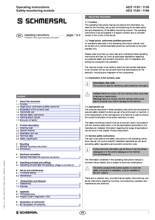
AES 1135 / 1136AES 1145 / 1146Operating instructions Safety-monitoring module11. 1.1 FunctionThis operating instructions manual provides all the information you need for the mounting, set-up and commissioning for the safe opera-tion and disassembly of the safety-monitoring module. The operating instructions must be available in a legible condition and a complete version in the vicinity of the device.1.2 Target group: authorised qualified personnelAll operations described in this operating instructions manual must be carried out by trained specialist personnel, authorised by the plant operator only.Please make sure that you have read and understood these operating instructions and that you know all applicable legislations regarding occupational safety and accident prevention prior to installation and putting the component into operation.The machine builder must carefully select the harmonised standards to be complied with as well as other technical specifications for the selection, mounting and integration of the components.1.3Explanation of the symbols usedInformation, hint, note:This symbol is used for identifying useful additional information.Caution:Failure to comply with this warning notice could lead to failures or malfunctions.Warning:Failure to comply with this warning notice could lead to physical injury and/or damage to the machine.1.4 Appropriate useThe products described in these operating instructions are developed to execute safety-related functions as part of an entire plant or machine. It is the responsibility of the manufacturer of a machine or plant to ensure the correct functionality of the entire machinery or plant.The safety-monitoring module must be exclusively used in accordance with the versions listed below or for the applications authorised by the manufacturer. Detailed information regarding the range of applications can be found in the chapter "Product description".1.5 General safety instructionsThe user must observe the safety instructions in this operating instruc-tions manual, the country-specific installation standards as well as allprevailing safety regulations and accident prevention rules.Further technical information can be found in the Schmersal catalogues or in the online catalogue on the Internet: .The information contained in this operating instructions manual isprovided without liability and is subject to technical modifications.The entire concept of the control system, in which the safety component is integrated, must be validated to EN ISO 13849-2.There are no residual risks, provided that the safety instructions as well as the instructions regarding mounting, commissioning, operation and maintenance are observed.1 About this document1.1 Function..............................................11.2 Target group: authorised qualified personnel..................11.3 Explanation of the symbols used...........................11.4 Appropriate use ........................................11.5 General safety instructions ...............................11.6 Warning about misuse...................................21.7 Exclusion of liability .....................................22 Product description2.1 Ordering code .........................................22.2 Special versions........................................22.3 Destination and use.....................................22.4 Technical data .........................................22.5 Safety classification.....................................23 Mounting3.1 General mounting instructions.............................33.2 Dimensions ...........................................34 Electrical connection4.1 General information for electrical connection (3)5 Operating principle and settings5.1 Operating principle after the operating voltage is switched on ....36 Set-up and maintenance6.1 Functional testing.......................................36.2 Maintenance ..........................................37 Disassembly and disposal7.1 Disassembly...........................................37.2 Disposal..............................................38 Appendix8.1 Wiring examples .......................................48.2 Integral System Diagnostics (ISD)..........................49 Declaration of conformity9.1 EC Declaration of conformity (5)x .000 / v .A . / 12.2011 / B Z -N r . 50137-17V 900 / T e i l e -N r . 1172884-E N / A u s g a b e EENOperating instructions. . . . . . . . . . . . .pages 1 to 6Translation of the original operating instructions2Operating instructions Safety-monitoring moduleAES 1135 / 1136AES 1145 / 11461.6Warning about misuseIn case of inadequate or improper use or manipulations of the safety-monitoring module, personal hazards or damages to machinery or plant components cannot be excluded. The relevant requirements of the standard EN 1088 must be observed.1.7 Exclusion of liabilityWe shall accept no liability for damages and malfunctions resulting from defective mounting or failure to comply with this operating instructions manual. The manufacturer shall accept no liability for damages result-ing from the use of unauthorised spare parts or accessories.For safety reasons, invasive work on the device as well as arbitrary re-pairs, conversions and modifications to the device are strictly forbidden; the manufacturer shall accept no liability for damages resulting from such invasive work, arbitrary repairs, conversions and/or modifications to the device.2. 2.1 Ordering codeThis operating instructions manual applies to the following types:Only if the information described in this operating instruc-tions manual are realised correctly, the safety function and therefore the compliance with the Machinery Directive is maintained.2.2 Special versionsFor special versions, which are not listed in the order code below 2.1, these specifications apply accordingly, provided that they correspond to the standard version.2.3 Destination and useThe safety-monitoring modules for integration in safety circuits are designed for fitting in control cabinets. They are used for the safe evaluation of the signals of positive break position switches for safety functions or magnetic safety sensors on sliding, hinged and removable safety guards as well as emergency stop control devices.DesignThe safety-monitoring modules have a dual-channel structure. They include two safety relays with monitored positive action contacts. The NO contacts of the relays, which are wired in series, build the enabling contacts.2.4 Technical data Standards:EN 60204-1; EN 60947-5-3; EN ISO 13849-1; IEC 61508; BG-GS-ET-14; BG-GS-ET-20Start conditions: Automatic Feedback circuit available: no Start-up test: AES ...5: no; AES ...6: yes Pull-in delay for automatic start: adjustable 0.1 / 1.0 second Drop-out delay in case of emergency stop: < 50 ms Rated operating voltage U e : 24 VDC Rated operating current I e : 0.2 A Rated insulation voltage U i : 250 V Rated impulse withstand voltage U imp : 4 kV Thermal test current I the : 6 A Internal electronic fuse: no Power consumption: < 5 W Inputs monitoring:Cross-wire short detection: yes Wire breakage detection: yes Earth connection detection: yes Number of NC contacts: convertible 1NC → 2NC Number of NO contacts: convertible 1NO → 0NO Outputs:Stop category 0: 1Stop category 1: 0Number of safety contacts: 1Number of auxiliary contacts: 0Number of signalling outputs: 2Switching capacity of the safety contacts: max. 6 A Switching capacity of the signalling outputs: Y1, Y2 = 100 mA Utilisation category to EN 60947-5-1: AC-15: 230 V / 3 ADC-13: 24 V / 2 AMax. fuse rating of the safety contacts: 6 A gG D-fuse Fuse rating of the signalling outputs: - AES 1135/1136: short-circuit proof; - AES 1145/1146: short-circuit proof, p-type Mechanical life: 20 million operations LED display : ISD Ambient conditions: Operating temperature: 0 °C ... +55 °C Storage and transport temperature: −25 °C ... +70 °C Protection class: Enclosure: IP40Terminals: IP20 Clearance: IP54Degree of pollution: 2Mounting: Snaps onto standard DIN rail to EN 60715Connection type: Screw connection Min. cable section: 0.25 mm²Max. Cable section: 2.5 mm², solid strand or multi-strandlead (including conductor ferrules)Tightening torque: 0,6 Nm Max. cable length: 1000 m of 0.75 mm² conductor Weight: 190 g Dimensions (H x W x D): 100 x 22.5 x 121 mm 2.5 Safety classification Standards: EN ISO 13849-1; IEC 61508PL: up to d Control category: up to 3PFH-value: 1.0 x 10⁻⁷ / h; Applicable for applications with upto max. 50,000 switching cycles / year andmax. 80 % contact load. Divergingapplications upon request.SIL: up to 2Service life: 20 years3AES 1135 / 1136AES 1145 / 1146Operating instructions Safety-monitoring module3. 3.1 General mounting instructionsMounting: snaps onto standard DIN rails to EN 60715.3.2 DimensionsDevice dimensions (H/W/D): 100 x 22.5 x 121 mm4. 4.1General information for electrical connectionThe electrical connection may only be carried out by authorised personnel in a de-energised condition.Wiring examples: see appendixTo avoid EMC disturbances, the physical ambient and operational conditions at the place where the product is installed, must meet the provisions laid down in the paragraph "Electromagnetic Compatibility (EMC)" of DIN EN 60204-1.5. 5.1 Operating principle after the operating voltage is switched on Without start-up test AES 1135 / AES 1145:1. The functionality of the safety-monitoring module is tested.2. I f the safety guard is closed or the emergency stop button released, the enabling paths of the safety-monitoring module will close. The LED is green.3. T he cable and the connected safety switch are only tested when the safety guard is opened or the emergency stop button when actuated With start-up test AES 1136 / AES 1146:1. The functionality of the safety-monitoring module is tested.2. T he safety guard or the emergency stop button must be actuated, in order to check the cables and the connected safety switch (start-up test).3. I f the safety guard is closed or the emergency stop button released, the enabling paths of the safety-monitoring module will close. The LED is green.If the safety guard is opened or the emergency-stop button is actuated, the enabling paths of the safety-monitoring module will open. The machine is stopped and the LED flashes yellow.Inputs: S14/S22Connect a safety switch with one NC and one NO contact or two safety switches with one contact each or an emergency-stop button at input S14/S22.Safety switch with two NC contacts: X1For an operation with two NC contacts, input X1 must be supplied with 24 VDC.OutputsEnabling paths 13-14: NO contacts for safety functionsAdditional outputs Y1/Y2:AES 1135/1136 Y 1: Authorized operation (release output closed)Y2: No authorized operation (release output opened)AES 1145/1146 Y 1: Safety guard opened (release output opened)Y2: Failure (release output opened)The additional outputs Y1 and Y2 must not be integrated in the safety circuit; they may only be used for signalling purposes.Enable delay timeThe enable delay time can be increased from 0.1 s to 1 s by changing the position of a jumper link connection. Remove the enclosure cover carefully by means of a screwdriver. Change the position of the jumper link connection B1.Jumper link connection closed = 1 s6. 6.1 Functional testingThe safety function of the safety-monitoring module must be tested. The following conditions must be previously checked and met:1. Correct fitting of the safety-monitoring module 2. Fitting and integrity of the power cable6.2 MaintenanceIn the case of correct installation and adequate use, the safety- monitoring module features maintenance-free functionality.We recommend a regular visual inspection and functional test, including the following steps:• Check the correct fixing of the safety monitoring module • Check the cable for damage.Damaged or defective components must be replaced.7. 7.1 DisassemblyThe safety monitoring module must be disassembled in the de- energised condition only.7.2 DisposalThe safety monitoring module must be disposed of in an appropriate manner in accordance with the national prescriptions and legislations.Operating instructions Safety-monitoring module AES 1135 / 1136 AES 1145 / 11468.8.1 Wiring examplesThe application examples shown are suggestions. They however do not release the user from carefully checking whether the switchgear and its set-up are suitable for the individual application.The wiring example refers to a closed safety guard and a voltage-free state. Inductive loads (e.g. contactors, relays, etc.) are to be p rovided with suitable interference suppression circuitry. Do not connect ad-ditional loads to terminal S..+24+24LegendA Positive breakA S Non-contact safety sensor A Safety switch 8.2 Integral System Diagnostics (ISD)The safety monitoring modules LED display to show the different switching conditions and faults. The following tables show the different switching conditions.Tables switching condition indicationIn case of error messages, the LED lights orange intermittently. During these intermissions, the LED flashes one up to seven times with short pulses.Table error indications* P artial actuation: position of the switch, in which only one contact was actuated. Deleting the error messageThe fault message is deleted once the fault has been rectified and after the connected switch has been actuated to check the various functions.45AES 1135 / 1136AES 1145 / 1146Operating instructions Safety-monitoring module9. The currently valid declaration of conformity can be downloaded from the internet at .9.1 EC Declaration of conformityAuthorised signature Heinz SchmersalK. A. Schmersal GmbHIndustrielle Sicherheitsschaltsysteme Möddinghofe 30, D - 42279 Wuppertal Postfach 24 02 63, D - 42232 Wuppertal Phone: +49 - (0)2 02 - 64 74 - 0 Telefax +49 - (0)2 02 - 64 74 - 1 00E-Mail: ****************** Internet: 。
安全帽功能说明与使用要求
安全帽功能说明与使用要求一、安全帽的定义安全帽是一种防止物体冲击、保护头部的劳动防护用品,属国家明确规定的头部护具类特种劳动防护用品,产品应当取得特种劳动防护用品安全标志(LA)。
安全帽的基本技术性能包括冲击吸收性能、耐穿刺性能、防静电性能、电绝缘性能、阻燃性能、侧向刚性及特殊技术性能等。
因此,安全帽不仅用于防止物体打击,还能起到防碰撞、防摔伤头部和一定的绝缘作用。
二、安全帽的结构安全帽由帽壳、帽衬、下颏带及其它附件组成。
(一)帽壳帽壳由壳体、帽舌、帽沿、顶筋、透气孔、插座、拴衬带孔及下颏带挂座等组成。
1.帽舌:帽壳前部伸出的部分,可以预防物体打击脸部;2.帽沿:帽壳除帽舌外周围伸出的部分,可有效预防物体打击头部的突出部位耳、鼻和脸部;3.顶筋:用来增强帽壳顶部强度的部分;4.透气孔:帽壳上开的气孔,可以起到透气及通风散热的作用,消除或减少闷热感;5.插座:帽壳与帽衬及附件连接的插入结构;6.连接孔:连接帽衬和帽壳的开孔。
(二)帽衬帽衬是帽壳内部部件的总称,由帽箍顶带、护带、托带、吸汗带、衬垫及拴绳等。
1.帽箍:绕头围部分起固定作用的带圈;2.护带:托带上面另加的一层不接触头顶的带子,起缓冲作用;3.托带:与头顶部直接接触的带子;4.吸汗带:包裹在帽箍外面的带状吸汗材料,有吸附汗水作用,免去不断擦汗的麻烦;5.衬垫:帽箍和帽壳之间起缓冲作用的垫;6.拴绳(带):连接托带和护带、帽衬和帽壳的绳(带);7.后箍:在帽箍后部加有可调节的箍;8.帽衬接头:连接帽衬和帽壳的接头。
(三)下颏带下颏带系在下颏上,起固定作用的带子,由系带和锁紧卡(调节下颏带长短的卡具)组成,有预防安全帽掉落的作用,即使大风吹、外力碰撞、高处坠落等安全帽也不会掉落。
三、安全帽的功能、作用(一)物理功能1.防止突然飞来物体对头部的打击。
飞来或垂直坠落的物体击向头部时,如果佩戴好合格的安全帽,就能有效预防头部受到伤害或减轻伤害程度;2.防止高处坠落时头部受伤害。
智能穿戴设备使用教程

智能穿戴设备使用教程第1章产品介绍与初步设置 (5)1.1 产品概述 (5)1.2 开箱及配件介绍 (5)1.3 佩戴方法 (5)1.4 设备激活与连接 (5)第2章界面与基本操作 (5)2.1 界面布局 (5)2.2 触摸屏操作 (5)2.3 功能键使用 (5)2.4 语音操作 (5)第3章通知与通话功能 (5)3.1 电话与短信通知 (5)3.2 社交应用通知 (5)3.3 通话功能操作 (5)3.4 语音拨号与联系人管理 (5)第4章运动与健康监测 (5)4.1 计步与距离统计 (5)4.2 卡路里消耗与运动目标 (5)4.3 心率监测 (5)4.4 睡眠监测与数据分析 (5)第5章音乐播放与控制 (6)5.1 音乐播放功能 (6)5.2 蓝牙耳机连接 (6)5.3 音乐控制操作 (6)5.4 音乐播放软件推荐 (6)第6章短信与通话功能 (6)6.1 发送接收短信 (6)6.2 通话记录查询 (6)6.3 常用通话功能设置 (6)6.4 语音转文字功能 (6)第7章系统设置与个性化 (6)7.1 亮度与音量调节 (6)7.2 主题与表盘更换 (6)7.3 语言与时间设置 (6)7.4 隐私与安全设置 (6)第8章附加功能与实用工具 (6)8.1 闹钟与日程提醒 (6)8.2 防丢与找手机 (6)8.3 天气与股票信息 (6)8.4 其他实用工具介绍 (6)第9章应用市场与第三方应用 (6)9.2 与安装应用 (6)9.3 常用第三方应用推荐 (6)9.4 应用管理及权限设置 (6)第10章蓝牙与网络连接 (6)10.1 蓝牙连接与配对 (6)10.2 WiFi网络连接 (6)10.3 移动网络设置 (6)10.4 网络应用场景介绍 (7)第11章电池与充电 (7)11.1 电池续航与充电方式 (7)11.2 充电注意事项 (7)11.3 电池优化与省电技巧 (7)11.4 电池故障排除与维护 (7)第12章常见问题与售后服务 (7)12.1 常见问题解答 (7)12.2 软件更新与升级 (7)12.3 售后服务与保修政策 (7)12.4 联系我们与客户服务 (7)第1章产品介绍与初步设置 (7)1.1 产品概述 (7)1.2 开箱及配件介绍 (7)1.3 佩戴方法 (7)1.4 设备激活与连接 (8)第2章界面与基本操作 (8)2.1 界面布局 (8)2.2 触摸屏操作 (8)2.3 功能键使用 (8)2.4 语音操作 (9)第3章通知与通话功能 (9)3.1 电话与短信通知 (9)3.1.1 电话通知 (9)3.1.2 短信通知 (9)3.2 社交应用通知 (9)3.2.1 常见社交应用通知 (9)3.2.2 通知管理 (9)3.3 通话功能操作 (10)3.3.1 拨打电话 (10)3.3.2 接听电话 (10)3.3.3 通话记录管理 (10)3.4 语音拨号与联系人管理 (10)3.4.1 语音拨号 (10)3.4.2 联系人管理 (10)第4章运动与健康监测 (10)4.2 卡路里消耗与运动目标 (10)4.3 心率监测 (11)4.4 睡眠监测与数据分析 (11)第5章音乐播放与控制 (11)5.1 音乐播放功能 (11)5.2 蓝牙耳机连接 (12)5.3 音乐控制操作 (12)5.4 音乐播放软件推荐 (12)第6章短信与通话功能 (12)6.1 发送接收短信 (12)6.1.1 发送短信 (12)6.1.2 接收短信 (13)6.2 通话记录查询 (13)6.2.1 查看通话记录 (13)6.2.2 管理通话记录 (13)6.3 常用通话功能设置 (13)6.3.1 呼叫等待 (13)6.3.2 呼叫转移 (13)6.3.3 呼叫限制 (14)6.4 语音转文字功能 (14)6.4.1 开启语音转文字功能 (14)6.4.2 查看语音转文字信息 (14)第7章系统设置与个性化 (14)7.1 亮度与音量调节 (14)7.1.1 亮度调节 (14)7.1.2 音量调节 (15)7.2 主题与表盘更换 (15)7.2.1 主题更换 (15)7.2.2 表盘更换 (15)7.3 语言与时间设置 (15)7.3.1 语言设置 (15)7.3.2 时间设置 (15)7.4 隐私与安全设置 (15)7.4.1 屏幕锁定 (15)7.4.2 应用权限管理 (15)7.4.3 隐私设置 (16)第8章附加功能与实用工具 (16)8.1 闹钟与日程提醒 (16)8.1.1 闹钟设置 (16)8.1.2 日程提醒设置 (16)8.2 防丢与找手机 (16)8.2.1 防丢功能 (16)8.2.2 找手机功能 (17)8.3.1 天气信息 (17)8.3.2 股票信息 (17)8.4 其他实用工具介绍 (17)8.4.1 计算器 (17)8.4.2 语音 (17)8.4.3 日历 (18)8.4.4 翻译器 (18)第9章应用市场与第三方应用 (18)9.1 应用市场简介 (18)9.2 与安装应用 (18)9.3 常用第三方应用推荐 (18)9.4 应用管理及权限设置 (18)第10章蓝牙与网络连接 (19)10.1 蓝牙连接与配对 (19)10.1.1 蓝牙基础知识 (19)10.1.2 蓝牙连接与配对过程 (19)10.1.3 蓝牙安全 (19)10.2 WiFi网络连接 (19)10.2.1 WiFi基础知识 (20)10.2.2 WiFi连接过程 (20)10.2.3 WiFi安全 (20)10.3 移动网络设置 (20)10.3.1 移动网络基础知识 (20)10.3.2 移动网络设置 (20)10.3.3 移动网络安全 (20)10.4 网络应用场景介绍 (21)10.4.1 家庭网络 (21)10.4.2 办公网络 (21)10.4.3 公共场所 (21)10.4.4 车载网络 (21)10.4.5 智能穿戴设备 (21)第11章电池与充电 (21)11.1 电池续航与充电方式 (21)11.1.1 电池类型 (21)11.1.2 充电方式 (21)11.1.3 提高电池续航能力 (22)11.2 充电注意事项 (22)11.2.1 使用原装充电器 (22)11.2.2 避免长时间充电 (22)11.2.3 避免高温充电 (22)11.2.4 避免低电量充电 (22)11.3 电池优化与省电技巧 (22)11.3.1 关闭不必要的功能 (22)11.3.3 优化应用使用 (23)11.4 电池故障排除与维护 (23)11.4.1 电池充放电异常 (23)11.4.2 电池发热 (23)11.4.3 电池寿命缩短 (23)第12章常见问题与售后服务 (23)12.1 常见问题解答 (23)12.2 软件更新与升级 (24)12.3 售后服务与保修政策 (24)12.4 联系我们与客户服务 (24)第1章产品介绍与初步设置1.1 产品概述1.2 开箱及配件介绍1.3 佩戴方法1.4 设备激活与连接第2章界面与基本操作2.1 界面布局2.2 触摸屏操作2.3 功能键使用2.4 语音操作第3章通知与通话功能3.1 电话与短信通知3.2 社交应用通知3.3 通话功能操作3.4 语音拨号与联系人管理第4章运动与健康监测4.1 计步与距离统计4.2 卡路里消耗与运动目标4.3 心率监测4.4 睡眠监测与数据分析第5章音乐播放与控制5.1 音乐播放功能5.2 蓝牙耳机连接5.3 音乐控制操作5.4 音乐播放软件推荐第6章短信与通话功能6.1 发送接收短信6.2 通话记录查询6.3 常用通话功能设置6.4 语音转文字功能第7章系统设置与个性化7.1 亮度与音量调节7.2 主题与表盘更换7.3 语言与时间设置7.4 隐私与安全设置第8章附加功能与实用工具8.1 闹钟与日程提醒8.2 防丢与找手机8.3 天气与股票信息8.4 其他实用工具介绍第9章应用市场与第三方应用9.1 应用市场简介9.2 与安装应用9.3 常用第三方应用推荐9.4 应用管理及权限设置第10章蓝牙与网络连接10.1 蓝牙连接与配对10.2 WiFi网络连接10.3 移动网络设置10.4 网络应用场景介绍第11章电池与充电11.1 电池续航与充电方式11.2 充电注意事项11.3 电池优化与省电技巧11.4 电池故障排除与维护第12章常见问题与售后服务12.1 常见问题解答12.2 软件更新与升级12.3 售后服务与保修政策12.4 联系我们与客户服务第1章产品介绍与初步设置1.1 产品概述本产品是一款集科技与时尚于一身的高功能智能设备,致力于为用户提供便捷、舒适的使用体验。
安全帽的使用说明

正确佩戴
佩戴前调整帽带松紧
佩戴时低于头部前突后缩
怎样正确使用安全帽
正确使用安全帽可有效降低意外伤害的发生率。在使用过程中,要注意定期检查帽壳和帽带的状态,合理佩戴并定期更换,避免长时间暴露于阳光下,保持清洁干燥等。只有正确使用安全帽,才能更好地保护自己的安全。
THANKS感谢观看
安全帽的使用说明
时间:2024年X月
汇报人:
第1章 安全帽的重要性
第2章 安全帽的注意事项
第3章 安全帽的选购指南
第4章 安全帽的维修保养
第5章 安全帽数码合格标准
第6章 安全帽的总结
第7章 结束
01
第1章 安全帽的重要性
Chapter
安全帽数码是工业和建筑行业中最重要的个人防护装备之一。安全帽的作用是保护头部免受意外伤害,减少事故发生时的伤害程度。
国家标准
维修保养
定期检查安全帽完整性,确保安全性能。清洁和储存安全帽数码,延长使用寿命。
质量要求
考虑安全性能和耐用性
选购符合质量要求的安全帽数码
合格认证
查看安全帽数码的合格认证标记
确保安全帽数码符合认证标准
耐用性
选择具有良好耐用性的安全帽数码
确保使用寿命长,性能稳定
安全帽数码合格标准
国家标准
减少外观污渍
深色安全帽
透气性
减少头部不适感
选择透气性好的安全帽
01
03
02
选择适合的透气性安全帽
考虑湿度和气候条件
可选购可调节尺寸安全帽
更加灵活适用
尺寸
根据头部大小选择合适尺寸的安全帽
不可过紧或过松
安全帽的选购指南总结
- 1、下载文档前请自行甄别文档内容的完整性,平台不提供额外的编辑、内容补充、找答案等附加服务。
- 2、"仅部分预览"的文档,不可在线预览部分如存在完整性等问题,可反馈申请退款(可完整预览的文档不适用该条件!)。
- 3、如文档侵犯您的权益,请联系客服反馈,我们会尽快为您处理(人工客服工作时间:9:00-18:30)。
成都筑邦科技有限公司IGH智能安全帽
使
用
说
明
书
IGH智能安全帽使用说明书
1、产品功能:
北斗(BD)定位
运动轨迹记录
运动数据监测
环境监测
佩戴监测
电子栅栏
语音通知
2、名称及示意图:
图一:安全帽示意图
正立面侧立面
A:帽壳B:智能模块C:固定支架A
B C
图二:智能模块(B)示意图
1.温湿度传感器
2.开关键
B接口
4.SOS键
5.距离感应器
6.PWR
7.STA
8.机身标贴位置
9.喇叭孔10.挂绳孔11.SIM卡位置开关机键
长按:关机状态长按5秒为开机(语音提示:“开机成功”),开机状态长按5秒为关机(语音提示:“关机成功”)。
短按:显示电源电量灯(详见指示灯说明)。
报警键
开机状态下长按SOS报警键5秒,启动SOS报警(语音提示:“报警成功”或“报警失败”)。
SIM卡槽
使用Micro SIM卡
电池充电
请使用附带的充电器进行充电。
3、SIM卡安装说明:
4、主要技术参数:
尺寸:40*58*9.5(mm)
机器净重:30g
GSM频道:900/1800MHZ
电池容量:750mAh
待机时间:140小时
SIM类型:Micro SIM卡
北斗频道:1575MHZ
定位精度误差:< 10米
热/冷启动时间:<5秒/<45秒
5、使用环境:
•在禁止使用无线设备的地方请关机。
如飞机、标明不可使用手机的医疗场所和医疗设备附近。
•请不要在可能会引起干扰或危险的地方开机使用设备。
如:加油站、易燃易爆品附近、爆破地点附近等。
6、指示灯说明:
SIM卡需要从卡槽中取出SIM卡时,请先关机。
充电当设备自动关机或显示“电量不足”警告时,应及时对电池充电。
充电环境为:5℃至40℃的通风处。
包装清单
智能安全帽 x1
USB 连接线x1
USB电源适配器x1
说明书x1
注:商标和版权的所有权归成都筑邦科技有限公司。