On ZC-based PSC and Frequency Offset
sampling frequency offset的定义
sampling frequency offset的定义**Sampling Frequency Offset Definition**Sampling frequency offset, also known as sampling rate offset, refers to the difference between the actual sampling frequency used in a digital signal processing system and the ideal or desired sampling frequency.采样频率偏移,也称为采样率偏移,是指数字信号处理系统中实际使用的采样频率与理想或期望的采样频率之间的差异。
This offset can occur due to various reasons, including imperfections in the analog-to-digital converter (ADC) ordigital-to-analog converter (DAC), clock jitter, or synchronization issues between different components of the system.这种偏移可能由于多种原因而发生,包括模拟到数字转换器(ADC)或数字到模拟转换器(DAC)的不完善、时钟抖动或系统不同组件之间的同步问题。
The existence of a sampling frequency offset can have significant impacts on the quality and accuracy of the processed digital signal. It can introduce distortions, aliasing effects, and phase errors, which can degrade the performance of signal processing algorithms and lead to inaccurate results.采样频率偏移的存在会对处理后的数字信号的质量和准确性产生显著影响。
蓝牙4.0低功耗测试规范

THE SPECIFICATION IS PROVIDED “AS IS” WITH NO WARRANTIES WHATSOEVER, INCLUDING ANY WARRANTY OF MERCHANTABILITY, NONINFRINGEMENT, FITNESS FOR ANY PARTICULAR PURPOSE, SATISFACTORY QUALITY, OR REASONABLE SKILL OR CARE, OR ANY WARRANTY ARISING OUT OF ANY COURSE OF DEALING, USAGE, TRADE PRACTICE, PROPOSAL, SPECIFICATION OR SAMPLE.
Use of the Specification by anyone who is not a member of Bluetooth SIG or a party to an Early Adopters Agreement (each such person or party, a “Member”) is prohibited. The legal rights and oerned by their applicable Membership Agreement, Early Adopters Agreement or Promoters Agreement. No license, express or implied, by estoppel or otherwise, to any intellectual property rights are granted herein.
2009-11-23 2009-11-25
2009-11-30 2009-10-11 2009-12-15 2009-12-15
sampling frequency offset的定义

sampling frequency offset的定义嘿,各位音频技术控们,今天咱们来聊点硬核又有趣的——sampling frequency offset(采样频率偏移),简称SFO。
这个概念虽然听起来有点抽象,但在我这生动活泼的解读下,你定会豁然开朗,如拨云见日。
想象一下,我们正在处理一段数字音频信号,就像是把流动的时间之河切割成无数个瞬间的照片——这些就是我们的“样本”。
而采样频率,就好比是摄影师按快门的速度,决定了我们每秒钟能捕捉多少个这样的瞬间。
理想情况下,这应该是恒定且精准无误的,然而现实中,由于种种原因(比如硬件不精确、信号传输过程中的干扰等),实际的采样频率可能会偏离预设的理想值,这就产生了所谓的SFO。
打个比方吧,你正准备按照44.1kHz的标准频率去录制一首歌,结果录音设备突然闹起了小脾气,实际采样速率一会儿高了那么一点点,一会儿又低了那么一丢丢,就像钟表走得不准时一样,这就相当于采样频率有了偏移。
这种偏差可能微乎其微,但在高度敏感的音频领域,哪怕是一丁点儿误差,都可能导致音质受损,甚至出现失真、混叠等让人头疼的问题。
所以说,SFO这家伙可不容小觑。
在进行数字信号处理或者通信系统设计的时候,我们需要像猫捉老鼠一样敏锐地揪出并纠正它。
这个时候,各种高级算法,比如频率锁定环路(Frequency-Locked Loop, FLL)和相位锁定环路(Phase-Locked Loop, PLL)就派上了用场,它们像是精密的导航仪,能够实时监测并调整采样频率,确保其始终与理想值保持同步。
哎呀,讲到这,是不是觉得SFO这玩意儿既神秘又接地气?其实,不论是音乐发烧友追求极致音质,还是科研人员攻关无线通信难题,理解并有效解决SFO都是至关重要的一步。
毕竟,在科技的世界里,细节决定成败,尤其是在音频信号这一毫厘千里的领域,对SFO的理解和掌控,无疑是我们迈向更高品质和更稳定通信效果的关键所在!所以,让我们一起握紧手中的“频率矫正器”,朝着更加精准无误的采样频率迈进,让每一个音符都能在理想的轨道上翩翩起舞,让每一段数据流都能在准确无误的频谱中自由翱翔吧!这就是sampling frequency offset的魅力所在,也是我们在探索音频科技之旅中必须面对和克服的一道挑战。
Turbo编码GMSK信号的多普勒频移捕获与跟踪

Turbo编码GMSK信号的多普勒频移捕获与跟踪吴团锋;徐友云;归琳;马文峰【摘要】提出了Turbo编码GMSK信号的多普勒频移捕获和跟踪方案.该方案首先采用AR模型进行多普勒频移的初始捕获,其次采用基于FFT的联合帧同步和频偏估计算法捕获剩余频差,最后利用判决反馈PLL跟踪多普勒频移的变化.仿真结果表明:该算法在低信噪比时可快速捕获超过符号速率的多普勒频移,并能以很小的误差跟踪多普勒频移的变化,此时解调器误码率性能恶化量较小.【期刊名称】《电讯技术》【年(卷),期】2011(051)008【总页数】5页(P61-65)【关键词】卫星移动通信;GMSK;Turbo码;多普勒频移;AR模型;判决反馈PLL环【作者】吴团锋;徐友云;归琳;马文峰【作者单位】上海交通大学无线通信技术研究所,上海200240;解放军理工大学通信工程学院,南京210007;上海交通大学无线通信技术研究所,上海200240;解放军理工大学通信工程学院,南京210007;上海交通大学无线通信技术研究所,上海200240;解放军理工大学通信工程学院,南京210007【正文语种】中文【中图分类】TN911.31 引言GMSK信号的包络恒定、相位连续,因此具有很多显著的优点,如射频功放可以工作在饱和区,充分利用发射机功率;对衰落环境不太敏感,邻道干扰较小等,因此在无线和卫星移动通信系统中得以成功应用[1]。
Turbo码在低信噪比条件下具有非常优异的性能[2],非常适合作为恶劣信道环境下的信道编码方案,因此,Turbo编码和GMSK调制相结合的方案是一种比较适合于卫星移动通信系统的传输体制[3],目前该体制已在某卫星通信系统中成功应用。
在卫星移动通信系统中,多普勒频移是影响通信性能的主要因素之一。
多普勒频移是由于地球站(例如机载站、车载站)的移动或者卫星的漂移产生的。
Ka频段具有频谱可用率高、潜在干扰小和设备体积小等优点,将成为未来卫星通信的主流和军事卫星通信发展的必然趋势。
MAX1069CCUD中文资料

ELECTRICAL CHARACTERISTICS
(AVDD = +4.75V to +5.25V, DVDD = +2.7V to +5.5V, fSCL = 1.7MHz (33% duty cycle), fSAMPLE = 58.6ksps, VREF = +4.096V, external reference applied to REF, REFADJ = AVDD, CREF = 10µF, TA = TMIN to TMAX, unless otherwise noted. Typical values are at TA = +25°C.)
Stresses beyond those listed under Байду номын сангаасAbsolute Maximum Ratings” may cause permanent damage to the device. These are stress ratings only, and functional operation of the device at these or any other conditions beyond those indicated in the operational sections of the specifications is not implied. Exposure to absolute maximum rating conditions for extended periods may affect device reliability.
MAX1069
Ordering Information
PART MAX1069ACUD MAX1069BCUD MAX1069CCUD MAX1069AEUD* MAX1069BEUD* TEMP RANGE 0°C to +70°C 0°C to +70°C 0°C to +70°C -40°C to +85°C -40°C to +85°C PINPACKAGE 14 TSSOP 14 TSSOP 14 TSSOP 14 TSSOP 14 TSSOP 14 TSSOP INL (LSB) ±1 ±2 ±3 ±1 ±2 ±3
基于PSoC芯片的两路高精度频率测量系统设计
基于PSoC芯片的两路高精度频率测量系统设计赵浩;吴斌【期刊名称】《电子设计工程》【年(卷),期】2014(000)015【摘要】In order to improve measure accuracy and broaden the frequency range, a frequency measure system of two-channel signal based on PSoC is proposed. The core processing unit of this system is CY8C29666. Based on the synchronous multi-cycle frequency measurement, and combined with the advantages of high integration, resourceful, flexible configuration and anti-jamming stability PSoC chips, the system performed high accuracy frequency measure of two-channel signal between 0.1 Hz~10M Hz. Based on the results, the measure accuracy is analyzed.%针对在脉冲频率测量中,测量精度低、频率范围窄等问题,提出了一种基于PSoC芯片的两路信号频率测量系统。
采用PSoC芯片CY8C29666作为系统核心,以改进的多周期同步测频法为理论基础,结合PSoC芯片集成度高、系统资源丰富、配置灵活、稳定抗干扰的优点,实现了对0.1 Hz~10 MHz之间两路信号频率的高精度测量,并结合实验结果进行了精度分析。
【总页数】3页(P174-176)【作者】赵浩;吴斌【作者单位】西北机电工程研究所陕西咸阳 712099;西北机电工程研究所陕西咸阳 712099【正文语种】中文【中图分类】TM935.1【相关文献】1.基于PSoC+CPLD的高精度位置伺服控制系统设计 [J], 张世文;2.高精度频率测量系统设计与实现 [J], 王勋3.CY8C29666芯片的高精度频率测量系统设计 [J], 赵浩;纪平鑫;周加永;李会营;吕启元4.基于DSP和CPLD的高精度频率测量系统设计 [J], 席鹏;李军;於二军5.基于IEEE1588时间同步的分布式桥梁健康监测系统基于BQ76pl455高精度电压采集芯片的储能电池管理系统设计 [J], 李雄伟;季钰林;谢伊亮;陈永强;李英祥因版权原因,仅展示原文概要,查看原文内容请购买。
AD9122器件手册
Dual, 16-Bit, 1230 MSPS,TxDAC+® Digital-to-Analog ConverterAD9122 Rev. AInformation furnished by Analresponsibility is assumed by Ana rights of third parties that may re license is granted by implication T rademarks and registered trad MA 02062-9106, U.S.A. Inc. All rights reserved.og Devices is believed to be accurate and reliable. However, nolog Devices for its use, nor for any infringements of patents or other sult from its use. Specifications subject to change without notice. No or otherwise under any patent or patent rights of Analog Devices. emarks are the property of their respective owners. One Technology Way, P.O. Box 9106, Norwood, Tel: 781.329.4700Fax: 781.461.3113 ©2010 Analog Devices,FEATURESFlexible LVDS interface allows word, byte, or nibble load Single-carrier W-CDMA ACLR = 82 dBc @ 122.88 MHz IF Analog output: adjustable 8.7 mA to 31.7 mA, R L = 25 Ω to 50 Ω Novel 2×/4×/8× interpolator/complex modulator allows carrier placement anywhere in the DAC bandwidthGain and phase adjustment for sideband suppression Multiple chip synchronization interfacesHigh performance, low noise PLL clock multiplierDigital inverse sinc filterLow power: 1.5 W @ 1.2 GSPS, 800 mW @ 500 MSPS, full operating conditions72-lead, exposed paddle LFCSPAPPLICATIONSWireless infrastructureW-CDMA, CDMA2000, TD-SCDMA, WiMAX, GSM, LTEDigital high or low IF synthesisTransmit diversityWideband communications: LMDS/MMDS, point-to-point GENERAL DESCRIPTIONThe AD9122 is a dual 16-bit, high dynamic range, digital-to-analog converter (DAC) that provides a sample rate of 1200 MSPS, permitting a multicarrier generation up to the Nyquist frequency. It includes features optimized for direct conversion transmit applications, including complex digital modulation, and gain and offset compensation. The DAC outputs are optimized to interface seamlessly with analog quadrature modulators, such as the ADL537x F-MOD series from Analog Devices, Inc. A 4-wire serial port interface provides for programming/readback of many internal parameters. Full-scale output current can be programmed over a range of 8.7 mA to 31.7 mA. The AD9122 comes in a 72-lead LFCSP.PRODUCT HIGHLIGHTS1.Ultralow noise and intermodulation distortion (IMD)enable high quality synthesis of wideband signals frombaseband to high intermediate frequencies.2. A proprietary DAC output switching technique enhancesdynamic performance.3.The current outputs are easily configured for varioussingle-ended or differential circuit topologies.4.Flexible LVDS digital interface allows the standard 32-wirebus to be reduced to ½ or ¼ of the width.TYPICAL SIGNAL CHAINCOMPLEX BASEBANDDC COMPLEX IFf IFRFLO – f IF8281-1 Figure 1.AD9122Rev. A | Page 2 of 60TABLE OF CONTENTSFeatures .............................................................................................. 1 Applications ....................................................................................... 1 General Description ......................................................................... 1 Product Highlights ........................................................................... 1 Typical Signal Chain ......................................................................... 1 Revision History ............................................................................... 3 Functional Block Diagram .............................................................. 4 Specifications ..................................................................................... 5 DC Specifications ......................................................................... 5 Digital Specifications ................................................................... 6 Digital Input Data Timing Specifications ................................. 6 AC Specifications .......................................................................... 7 Absolute Maximum Ratings ............................................................ 8 Thermal Resistance ...................................................................... 8 ESD Caution .................................................................................. 8 Pin Configuration and Function Descriptions ............................. 9 Typical Performance Characteristics ........................................... 11 Terminology .................................................................................... 17 Differences Between the AD9122R1 and AD9122R2 ............... 18 Theory of Operation ...................................................................... 19 Serial Port Operation ................................................................. 19 Data Format ................................................................................ 19 Serial Port Pin Descriptions ...................................................... 19 Serial Port Options ..................................................................... 20 Device Configuration Register Map and Descriptions ......... 21 LVDS Input Data Ports .................................................................. 33 Word Interface Mode ................................................................. 33 Byte Interface Mode ................................................................... 33 Nibble Interface Mode ............................................................... 33 FIFO Operation .......................................................................... 33 Interface Timing ......................................................................... 35 Digital Datapath .............................................................................. 37 Premodulation ............................................................................ 37 Interpolation Filters ................................................................... 37 NCO Modulation ....................................................................... 40 Datapath Configuration ............................................................ 40 Determining Interpolation Filter Modes ................................ 41 Datapath Configuration Example ............................................ 42 Data Rates vs. Interpolation Modes ......................................... 43 Coarse Modulation Mixing Sequences .................................... 43 Quadrature Phase Correction ................................................... 44 DC Offset Correction ................................................................ 44 Inverse Sinc Filter ....................................................................... 44 DAC Input Clock Configurations ................................................ 45 DAC Input Clock Configurations ............................................ 45 Analog Outputs............................................................................... 47 Transmit DAC Operation .......................................................... 47 Auxiliary DAC Operation ......................................................... 48 Baseband Filter Implementation .............................................. 49 Driving the ADL5375-15 .......................................................... 49 Reducing LO Leakage and Unwanted Sidebands .................. 50 Device Power Dissipation .............................................................. 51 Temperature Sensor ................................................................... 52 Multichip Synchronization ............................................................ 53 Synchronization with Clock Multiplication ............................... 53 Synchronization with Direct Clocking .................................... 54 Data Rate Mode Synchronization ............................................ 54 FIFO Rate Mode Synchronization ........................................... 55 Additional Synchronization Features ...................................... 55 Interrupt Request Operation ........................................................ 57 Interrupt Service Routine .......................................................... 57 Interface Timing Validation .......................................................... 58 SED Operation ............................................................................ 58 SED Example .............................................................................. 58 Example Start-Up Routine ........................................................ 59 Outline Dimensions ....................................................................... 60 Ordering Guide .. (60)AD9122Rev. A | Page 3 of 60REVISION HISTORY3/10—Rev. 0 to Rev. AChanges to Reflect Differences Between R1 and R2Silicon................................................................................... Universal Changes to Features Section ............................................................ 1 Changes to Table 1 ............................................................................ 5 Changes to Table 2 ............................................................................ 6 Changes to Table 5 ............................................................................ 7 Change to IOVDD Rating in Table 6 .............................................. 8 Changes to Table 8 ............................................................................ 9 Changes to Figure 10 to Figure 15 ................................................ 12 Added Differences Between the AD9122R1 and AD9122R2 Section, Added Figure 36 and Figure 37; RenumberedSequentially ...................................................................................... 18 Changes to Table 10 ........................................................................ 21 Changes to Table 11 ........................................................................ 23 Changes to FIFO Operation Section ............................................ 33 Changes to Resettling the FIFO Section and Replaced Table 13; Renumbered Sequentially; Added Serial Port Initiated FIFO Reset Section, and Added FRAME Initiated Relative FIFOReset Section .................................................................................... 34 Added FRAME Initiated Absolute FIFO Reset Section andReplaced Table 14 ............................................................................ 35 Changes to Figure 54 ...................................................................... 38 Changes to Table 18 ........................................................................ 39 Changes to SED Example Section ................................................. 58 Added Example Start-Up Routine Section .................................. 59 9/09—Revision 0: Initial VersionAD9122Rev. A | Page 4 of 60FUNCTIONAL BLOCK DIAGRAMD15P—D15ND0P—D0NIOUT1P IOUT1NIOUT2P IOUT2NFSADJREFIO DCI FRAME08281-002Figure 2. AD9122 Functional Block DiagramAD9122Rev. A | Page 5 of 60SPECIFICATIONSDC SPECIFICATIONST MIN to T MAX , AVDD33 = 3.3 V , DVDD18 = 1.8 V , CVDD18 =1.8 V , I OUTFS = 20 mA, maximum sample rate, unless otherwise noted. Table 1.Parameter Min Typ Max Unit RESOLUTION 16 Bits ACCURACY Differential Nonlinearity (DNL) ±2.1 LSB Integral Nonlinearity (INL) ±3.7 LSB MAIN DAC OUTPUTS Offset Error −0.001 0 +0.001 % FSR Gain Error (with Internal Reference) −3.6 ±2 +3.6 % FSR Full-Scale Output Current 18.66 19.6 31.66 mA Output Compliance Range −1.0 +1.0 V Output Resistance 10 MΩ Gain DAC Monotonicity Guaranteed Settling Time to Within ±0.5 LSB 20 ns MAIN DAC TEMPERATURE DRIFT Offset 0.04 ppm/°C Gain 100 ppm/°C Reference Voltage 30 ppm/°C REFERENCE Internal Reference Voltage 1.2 V Output Resistance 5 kΩ ANALOG SUPPLY VOLTAGES AVDD33 3.13 3.3 3.47 V CVDD18 1.71 1.8 1.89 V DIGITAL SUPPLY VOLTAGES DVDD18 1.71 1.8 1.89 V IOVDD 1.71 1.8/3.3 3.47 V POWER CONSUMPTION 2× Mode, f DAC = 491.22 MSPS, IF = 10 MHz, PLL Off 834 mW 2× Mode, f DAC = 491.22 MSPS, IF = 10 MHz, PLL On 913 mW 8× Mode, f DAC = 800 MSPS, IF = 10 MHz, PLL Off 1135 1241 mWAVDD33 55 57 mA CVDD18 85 90 mA DVDD18 444 495 mA Power-Down Mode (Register 0x01 = 0xF1) 6.5 18.8 mW Power Supply Rejection Ratio, AVDD33 −0.3 +0.3 % FSR/V OPERATING RANGE −40 +25 +85 °C1Based on a 10 kΩ external resistor.AD9122Rev. A | Page 6 of 60DIGITAL SPECIFICATIONST MIN to T MAX , AVDD33 = 1.8 V , IOVDD = 3.3 V , DVDD18 = 1.8 V , CVDD18 = 1.8 V , I OUTFS = 20 mA, maximum sample rate, unless otherwise noted.1LVDS receiver is compliant to the IEEE 1596 reduced range link, unless otherwise noted.DIGITAL INPUT DATA TIMING SPECIFICATIONSTable 3.Parameter Min Typ Max UnitLATENCY (DACCLK Cycles) 1× Interpolation (With or Without Modulation) 64 Cycles 2× Interpolation (With or Without Modulation) 135 Cycles 4× Interpolation (With or Without Modulation) 292 Cycles 8× Interpolation (With or Without Modulation) 608 Cycles Inverse Sinc 20 Cycles Fine Modulation 8 Cycles Power-Up Time 260 msAD9122Rev. A | Page 7 of 60AC SPECIFICATIONST MIN to T MAX , AVDD33 = 3.3 V , DVDD18 = 1.8 V , CVDD18 = 1.8 V , I OUTFS = 20 mA, maximum sample rate, unless otherwise noted. Table 4.ParameterMin Typ Max UnitSPURIOUS-FREE DYNAMIC RANGE (SFDR) f DAC = 100 MSPS, f OUT = 20 MHz 78 dBc f DAC = 200 MSPS, f OUT = 50 MHz 80 dBc f DAC = 400 MSPS, f OUT = 70 MHz 69 dBc f DAC = 800 MSPS, f OUT = 70 MHz72 dBc TWO-TONE INTERMODULATION DISTORTION (IMD) f DAC = 200 MSPS, f OUT = 50 MHz 84 dBc f DAC = 400 MSPS, f OUT = 60 MHz 86 dBc f DAC = 400 MSPS, f OUT = 80 MHz 84 dBc f DAC = 800 MSPS, f OUT = 100 MHz81 dBc NOISE SPECTRAL DENSITY (NSD) EIGHT-TONE, 500 kHz TONE SPACING f DAC = 200 MSPS, f OUT = 80 MHz −162 dBm/Hz f DAC = 400 MSPS, f OUT = 80 MHz −163 dBm/Hz f DAC = 800 MSPS, f OUT = 80 MHz−164 dBm/Hz W-CDMA ADJACENT CHANNEL LEAKAGE RATIO (ACLR), SINGLE CARRIER f DAC = 491.52 MSPS, f OUT = 10 MHz 84 dBc f DAC = 491.52 MSPS, f OUT = 122.88 MHz 82 dBc f DAC = 983.04 MSPS, f OUT = 122.88 MHz 83 dBc W-CDMA SECOND ACLR, SINGLE CARRIER f DAC = 491.52 MSPS, f OUT = 10 MHz 88 dBc f DAC = 491.52 MSPS, f OUT = 122.88 MHz 86 dBc f DAC = 983.04 MSPS, f OUT = 122.88 MHz88dBcTable 5. Interface SpeedsBus Width Interpolation Factorf BUS (Mbps)1.8 V ± 5% 1.8 V ± 2% 1.9 V ± 5% Nibble (4 Bits) 1×1100 1200 1230 2× (HB1) 1100 1200 1230 2× (HB2) 1100 1200 1230 4× 1100 1200 1230 8× 1100 1200 1230 Byte (8 Bits) 1×1100 1200 1230 2× (HB1) 1100 1200 1230 2× (HB2) 1100 1200 1230 4× 1100 1200 1230 8× 550 600 615 Word (16 Bits) 1×1100 1200 1230 2× (HB1) 900 1000 1000 2× (HB2) 1100 1200 1230 4× 550 600 615 8×275 300 307.5AD9122Rev. A | Page 8 of 60ABSOLUTE MAXIMUM RATINGSTHERMAL RESISTANCEThe exposed paddle (EPAD) must be soldered to the ground plane for the 72-lead, LFCSP . The EPAD performs as an electrical and thermal connection to the board.Typical θJA , θJB , and θJC are specified for a 4-layer board in still air. Airflow increases heat dissipation effectively reducing θJA and θJB . Table 7. Thermal ResistancePackage θJA θJB θJC Unit Conditions 72-Lead LFCSP_VQ 20.7 10.9 1.1 °C/W EPAD solderedESD CAUTIONStresses above those listed under Absolute Maximum Ratings may cause permanent damage to the device. This is a stress rating only; functional operation of the device at these or any other conditions above those indicated in the operationalsection of this specification is not implied. Exposure to absolute maximum rating conditions for extended periods may affect device reliability.AD9122Rev. A | Page 9 of 6008281-003D 11P D 11N D 10P D 10N D 9P D 9N D 8P D 8N D C I D C I D V D D 18D V S D 7P D 7N D 6P D 6N D 5P D 5N PIN CONFIGURATION AND FUNCTION DESCRIPTIONS12345678910111213141516CVDD18DACCLKP DACCLKNCVSS FRAMEP FRAMENIRQ D15P D15N NC IOVDD DVDD18D14P D14N D13P D13N 17D12P 18D12N 19202122232425262728293031323334P N S 3536545352515049484746454443424140393837RESET CS SCLK SDIO SDO DVDD18D0N D0P D1N D1P DVSS DVDD18D2N D2P D3N D3P D4N D4P727170696867666564636261605958575655C VD D 18C V D D 18REF C L K P R E F C L K N A V D D 33I O U T 1P I O U T 1N A V D D 33A V S S F S A D J R E F I O A V S S A V D D 33I O U T 2N I O U T 2P A V D D 33A V S S NCNOTES1. NC = NO CONNECT.2. EXPOSED PAD MUST BE CONNECTED TO AVSS.Figure 3. Pin ConfigurationAD9122Rev. A | Page 10 of 60AD9122050100150200250300350400450f OUT (MHz)TYPICAL PERFORMANCE CHARACTERISTICS0–10–20–30–40–50–60–70–80–90–100H A R M O N I C S (d B c)08281-10150100150200250300350400450f OUT (MHz)Figure 4. Harmonics vs. f OUT over f DATA , 2× Interpolation,Digital Scale = 0 dBFS, f SC = 20 mA0–10–20–30–40–50–60–70–80–90–100H A R M O N I C S (d B c )08281-10208281-1030–10–20–30–40–50–60–70–80–90–100050100150200250300350400450H A R M O N I C S (d B c )f OUT(MHz)08281-1040–10–20–30–40–50–60–70–80–90–10050100150200250300350400450H A R M O N I C S (d B c )f OUT (MHz)Figure 7. Second Harmonic vs. f OUT over Digital Scale, 2× Interpolation,f DATA = 400 MSPS, f SC= 20 mA08281-1050–10–20–30–40–50–60–70–80–90–10050100150200250300350400450H A R M O N I C S (d B c )f OUT (MHz)Figure 5. Harmonics vs. f OUT over f DATA , 4× Interpolation,Digital Scale = 0 dBFS, f SC = 20 mAFigure 8. Third Harmonic vs. f OUT over Digital Scale, 2× Interpolation,f DATA = 400 MSPS, f SC = 20 mA0–10–20–30–40–50–60–70–80–90–100H A R M O N I C S (d B c )100200300400500600700f OUT (MHz)08281-106Figure 6. Harmonics vs. f OUT over f DATA , 8× Interpolation,Digital Scale = 0 dBFS, f SC = 20 mA Figure 9. Second Harmonic vs. f OUT over f SC , 2× Interpolation,f DATA = 400 MSPS, Digital Scale = 0 dBFSAD9122–69–70–71–72–73–74–75–77H I G H E S T D I G I T A L S P U R (d B c )–78–79050100150200250300350400450f OUT (MHz)–7608281-10708281-110START 1.0MHz #RES BW 10kHzVBW 10kHzSTOP 500.0MHzSWEEP 6.017s (601 PTS)08281-111START 1.0MHz #RES BW 10kHzVBW 10kHzSTOP 800.0MHzSWEEP 9.634s (601 PTS)Figure 10. Highest Digital Spur vs. f OUT over f DATA , 2× Interpolation,Digital Scale = 0 dBFS, f SC = 20 mA–60–65–70–75–80–85H I G H E S T D I G I T A L S P U R (d B c )050100150200250300350400450f OUT (MHz)08281-108Figure 11. Highest Digital Spur vs. f OUT over f DATA , 4× Interpolation,Digital Scale = 0 dBFS, f SC = 20 mA–60–90–95–85–80–75–70–65H I G H E S T D I G I T A L S P U R (d B c )010*******400500600700f OUT (MHz)08281-109Figure 12. Highest Digital Spur vs. f OUT over f DATA , 8× Interpolation,Digital Scale = 0 dBFS, f SC = 20 mAFigure 13. 2× Interpolation, Single-Tone Spectrum, f DATA = 250 MSPS,f OUT= 101 MHzFigure 14. 4× Interpolation, Single-Tone Spectrum, f DATA = 200 MSPS,f OUT = 151 MHz08281-START 1.0MHz #RES BW 10kHzVBW 10kHzSTOP 800.0MHzSWEEP 9.634s (601 PTS)112Figure 15. 8× Interpolation, Single-Tone Spectrum, f DATA = 100 MSPS,f OUT = 131 MHzAD91220–90–80–70–60–50–40–30–20–10I M D (d B c )050100150200250300350400450f OUT (MHz)308281-11Figure 16. IMD vs. f OUT over f DATA , 2× Interpolation,Digital Scale = 0 dBFS, f SC = 20 mA0–80–70–60–50–40–30–20–10–90I M D (d B c )050100150200250300350400450f OUT (MHz)408281-11Figure 17. IMD vs. f OUT over f DATA , 4× Interpolation,Digital Scale = 0 dBFS, f SC = 20 mA0–80–70–60–50–40–30–20–10I M D (d B c )–100–90050100150200250300350400450f OUT(MHz)08281-115Figure 18. IMD vs. f OUT over f DATA , 8× Interpolation,Digital Scale = 0 dBFS, f SC = 20 mA0–90–80–70–60–50–40–30–20–10050100150200250300350400450I M D (d B c )f OUT(MHz)08281-116Figure 19. IMD vs. f OUT over Digital Scale, 2× Interpolation,f DATA = 400 MSPS, f SC = 20 mA–50–85–80–75–70–65–60–55050100150200250300350400450I M D (d B c )f OUT (MHz)08281-117Figure 20. IMD vs. f OUT over f SC , 2× Interpolation, f DATA = 400 MSPS,Digital Scale = 0 dBFS–40–90–85–80–75–70–65–60–55–50–45I M D (d B c)050100150200250300350400450f OUT (MHz)08281-118Figure 21. IMD vs. f OUT , PLL On vs. PLL Off, 4× Interpolation, f DATA = 200 MSPS,Digital Scale = 0 dBFS, f SC = 20 mAAD9122–152–156–154–158–160–162–164––166N S D (d B m /H z )50100150200250300350400450f OUT (MHz)908281-11Figure 22. 1-Tone NSD vs. f OUT over Interpolation Rate, Digital Scale = 0 dBFS,f SC = 20 mA, PLL Off–154–158–156–160–162–164–166–168N S D (d B m /H z )050100150200250300350400450f OUT (MHz)08281-12Figure 23. 1-Tone NSD vs. f OUT over Digital Scale, f DATA = 200 MSPS,4× Interpolation, f SC = 20 mA, PLL Off–158–159–160–161–162–163–164–165N S D (d B m /H z )–166050100150200250300350400450f OUT (MHz)08281-121Figure 24. 1-Tone NSD vs. f OUT over Interpolation Rate, Digital Scale = 0 dBFS,f SC = 20 mA, PLL On 161.0–165.5–165.0–164.5–164.0–163.5–163.0–162.5–162.0–161.5050100150200250300350400450N S D (d B m /H z )f OUT(MHz)08281-122Figure 25. 8-Tone NSD vs. f OUT over Interpolation Rate, Digital Scale = 0 dBFS,f SC = 20 mA, PLL Off–161.0–166.5–165.5–166.0–165.0–164.5–164.0–163.5–163.0–162.5–162.0–161.5050100150200250300350400450N S D (d B m /H z )fOUT (MHz)08281-123Figure 26. 8-Tone NSD vs. f OUT over Digital Scale, f DATA = 200 MSPS,4× Interpolation, f SC = 20 mA, PLL Off–160–161–162–163–164–165–166N S D (d B m /H z)050100150200250300350400450f OUT (MHz)08281-124Figure 27. 8-Tone NSD vs. f OUT over Interpolation Rate, Digital Scale = 0 dBFS,f SC = 20 mA, PLL OnAD9122–77–84–83–82–81–80–79–78A C L R (d B c )–050100150200250fOUT (MHz)50–55–60–65–70–75–80–85–900100200300400500A C L R (dB c )f OUT(MHz)08281-12508281-128Figure 28. 1-Carrier W-CDMA ACLR vs. f OUT over Digital Scale,Adjacent Channel, PLL Off–78–88–86–84–82–80–90A C L R (dB c )050100150200250fOUT (MHz)08281-126Figure 29. 1-Carrier W-CDMA ACLR vs. f OUT over f DAC ,Alternate Channel, PLL Off–70–90–85–80–75A C L R (dB c )–95050100150200250fOUT (MHz)08281-127Figure 30. 1-Carrier W-CDMA ACLR vs. f OUT over f DAC ,Second Alternate Channel, PLL Off Figure 31. 1-Carrier W-CDMA ACLR vs. f OUT , Adjacent Channel,PLL On vs. PLL Off–70–72–74–76–78–80–82–84–86–88–900100200300400500A C L R (dB c )f OUT(MHz)08281-129Figure 32. 1-Carrier W-CDMA ACLR vs. f OUT , Alternate Channel,PLL On vs. PLL Off–70–95–90–85–80–75A C L R (dB c)0100200300400500f OUT (MHz)08281-130Figure 33. 1-Carrier W-CDMA ACLR vs. f OUT , Second Alternate Channel,PLL On vs. PLL OffAD912208281-131START 133.06MHz #RES BW 30kHzVBW 30kHz STOP 166.94MHzSWEEP 143.6ms (601 PTS)START 125.88MHz #RES BW 30kHz VBW 30kHz STOP 174.42MHzSWEEP 206.9ms (601 PTS)TOTAL CARRIER POWER –11.19dBm/15.3600MHz RRC FILTER: OFF FILTER ALPHA 0.22REF CARRIER POWER –16.89dBm/3.84000MHzLOWER UPPER OFFSET FREQ INTEG BW dBc dBm dBc dBm 1–16.92dBm 5.000MHz 3.840MHz –65.88–82.76–67.52–84.40RMS RESULTS FREQ LOWER UPPER OFFSET REF BW dBc dBm dBc dBm CARRIER POWER 5.00MHz 3.840MHz –75.96–85.96–77.13–87.13–10.00dBm/10.00MHz 3.840MHz –85.33–95.33–85.24–95.253.840MHz15.00MHz2.888MHz–95.81–95.81–85.43–95.4308281-1322–16.89dBm 10.00MHz 3.840MHz –68.17–85.05–69.91–86.793–17.43dBm 15.00MHz 3.840MHz–70.42–87.31–71.40–88.284–17.64dBmFigure 35. 1-Carrier W-CDMA ACLR Performance, IF = ~150 MHzFigure 34. 4-Carrier W-CDMA ACLR Performance, IF = ~150 MHzAD9122 TERMINOLOGYIntegral Nonlinearity (INL)INL is defined as the maximum deviation of the actual analog output from the ideal output, determined by a straight line drawn from zero scale to full scale.Differential Nonlinearity (DNL)DNL is the measure of the variation in analog value, normalized to full scale, associated with a 1 LSB change in digital input code. Offset ErrorThe deviation of the output current from the ideal of zero is called offset error. For IOUT1P, 0 mA output is expected when the inputs are all 0s. For IOUT1N, 0 mA output is expected when all inputs are set to 1.Gain ErrorThe difference between the actual and ideal output span. The actual span is determined by the difference between the output when all inputs are set to 1 and the output when all inputs are set to 0.Output Compliance RangeThe range of allowable voltage at the output of a current output DAC. Operation beyond the maximum compliance limits can cause either output stage saturation or breakdown, resulting in nonlinear performance.Temperature DriftTemperature drift is specified as the maximum change from the ambient (25°C) value to the value at either T MIN or T MAX. For offset and gain drift, the drift is reported in ppm of full-scale range (FSR) per degree Celsius. For reference drift, the drift is reported in ppm per degree Celsius.Power Supply Rejection (PSR)The maximum change in the full-scale output as the supplies are varied from minimum to maximum specified voltages. Settling TimeThe time required for the output to reach and remain within a specified error band around its final value, measured fromthe start of the output transition.Spurious Free Dynamic Range (SFDR)The difference, in decibels, between the peak amplitude of the output signal and the peak spurious signal within the dc to the Nyquist frequency of the DAC. Typically, energy in this band is rejected by the interpolation filters. This specification, therefore, defines how well the interpolation filters work and the effect of other parasitic coupling paths to the DAC output.Signal-to-Noise Ratio (SNR)SNR is the ratio of the rms value of the measured output signal to the rms sum of all other spectral components below the Nyquist frequency, excluding the first six harmonics and dc. The value for SNR is expressed in decibels.Interpolation FilterIf the digital inputs to the DAC are sampled at a multiple rate of f DATA (interpolation rate), a digital filter can be constructed that has a sharp transition band near f DATA/2. Images that typically appear around f DAC (output data rate) can be greatly suppressed. Adjacent Channel Leakage Ratio (ACLR)The ratio in decibels relative to the carrier (dBc) between the measured power within a channel relative to its adjacent channel. Complex Image RejectionIn a traditional two-part upconversion, two images are created around the second IF frequency. These images have the effect of wasting transmitter power and system bandwidth. By placing the real part of a second complex modulator in series with the first complex modulator, either the upper or lower frequency image near the second IF can be rejected.。
“内转外”船舶检验类型分析
·1·文章编号:2095-3747(2024)-01-0001-04“内转外”船舶检验类型分析田大春(舟山海事局,浙江 舟山361000)摘要:通过一则港口国监督检查案例,对“内转外”船舶检验类型进行探讨和分析,明晰了其初次检验类型,提出了避免因船舶检验类型错误导致PSC 滞留的相关建议。
关键词:法定检验;船旗国;船级社;压载水管理系统;港口国检查中图分类号:U698 文献标识码:A 收稿日期:2023-06-15作者简介:田大春(1983— ),男,PSC 检察官从2022年开始,内、外贸干散货船运输市场出现分化,内贸干散货船东利润压缩严重,许多内贸干散货船东通过改建、换旗改航外贸市场。
内贸船转外贸船面临不少问题需要解决,如改建投资、设备添加、船员配备、国际安全管理体系(ISM)运行、港口国监督检查(PSC)应对等。
这些对“内转外”(内贸沿海航行船舶转国外方便旗国际航行)的船东存在很大挑战。
同样,此类船舶换旗检验和登记质量控制也存在很多问题亟需解决,如建造规范的适用性、换旗检验的类型、设备安装时间节点等。
解决这些问题船级社才能在船旗国授权下签发相关法定证书进行营运。
最近,我们就发现有些船舶在日本PSC 检查中,因相关证书最近一次检验日期与检验类型不符,换旗相应时间节点应安装的设备如压载水管理系统未安装而遭到滞留。
1港口国监督检查案例1.1船舶基本信息船旗国:塞拉利昂。
船舶种类:干货船。
IMO 编号:8XXXXXX。
建造日期:2004.11.8。
船级社:ASCS。
总吨:2785。
“内转外”日期:2021年11月18日。
1.2检查概况及跟踪处理情况2022年11月8日,日本川崎港港口国检查官(PSCO)对该船进行PSC 检查,检查发现缺陷45项,其中与换旗检验类型有关的缺陷有2项。
缺陷描述如表1:表1 与换旗检验类型有关的缺陷缺陷代码缺陷描述处理意见01199包括船舶结构证书、安全设备证书、国际防止油污证书、国际防止大气污染证书、国际防止生活污水污染证书、载重线证书、国际压载水管理证书等几乎所有证书,检验完成的日期基于2019年6月8日,但是,在此期间,该船属于内贸沿海航行船舶。
城市轨道交通专业词汇缩写总汇
城市轨道交通专业词汇缩写AC:信标/计轴AX? Count?rACS 计轴系统Axle Counter SystemADC:自动关门Auto Door Close?ADO:自动开门Auto Door OpenADM :系统管理器?ADU:特征显示单?元AF:音频AFC 自动售检票?系统Au?o Fare Colietion?AM:列车自动运行驾驶模式Automatic Model?AMU: ATO匹配单元AP:接入点、轨旁无线单?元/应用模块ApplicOtionF APAM:ATO功率放大板块API:应用程序接?口APR绝对位置参?考应答器、信标AR:自动折返驾?驶列车自动折?返莫式ARS列车进路设?定AS:管理服务器?接入交换机AcceS? Switc?ASK数字调幅、幅移键控ATB 自动折返按?钮Automatic?Turnb?ck ButtonATC列车自动控?制系统ATI:列车到达时?刻显示器ATO列车自动运?行ATP列车自动防?护ATR列车自动调?整‘ATS 列车自动监?控Aut?matic?Train?Super?isio?AXC计轴器B&A :操作和显示?BAS环境与设备?监控系统Bd:波特bond:棒BS:骨干交换机BackbOne SwitchBUMA:总线控制板?CA控制中心自动控制模、中央自动模?式CAN:现场总线CAZ冲突防护区?域’CBI计算机联锁Computer Based?nter?)cki?gCBN 通信系统CBTC 基于通信的?列车控制C?ommuni?cati?on Based?Train?Contro?l CC 车载控制器?Ca rbo r?n e Contro?ller?CCTE车载安全计?算机(包括ATP/AT0子系统)CCTV 闭路电视/电视监视器?CD 载频检测模?块CDM 电码检测模?块CDTA 中央数据传?输系统CE 控制设备CENEL?EC 欧洲电工标?准委员会CESB 中央紧急停?车按钮CER 控制室CG 编码发生器?CH 校核信号CI 计算机联锁?Comput?er Based?Interl?ocki?ngCLC 线路控制器?CL0W 中央联锁工?作站Ce?nter Lockin?g Workst?atio?nCM 编码人工驾?驶模式C0AST? 惰行C0M 通信服务器?COTS可购买的商?用产品CPL耦合器模块CouplerCPISA通信处理器?CPS条件电源块?CPU 中央处理单?元CRC 循环冗余校?验CRT 阴极射线显?示器CS 中央服务器?Cente r? Server?CSEX 电码系统模?拟器扩展CTC 调度集中CTS 光数据传输?系统DAB 报警按钮(为了及时处?理意外或临?时事故而设?置在车厢里?的乘客报警按钮)DB 轨道数据库?Data BaseDCC;元件接口模?块车辆段、停车场控制?中心De?ot Contr?l Cente?DCS数据通信系?统DataCommunicatfiOn SubsystemDCU:数据储存单?元DCR 车站综合控?制室DDS 数字频率合?成技术、DDU 诊断和数据?上载单元、诊断和数据?更新单元DEBL?MI O 闪光元件接?口模块DEM 调节器DESIM?O 信号机元件?接口模块DEWEM?O 道岔元件接?口模块DI 列车发车时?刻显示器DID 目的地号D?estin?ation?Identi?ficat?ionDIOM 离散输入、输出板块DOC 驱动输出模?块DOT 倒换方向DPU:车辆段程序?单元DS:模拟MMI?、演示系统、数据服务器?DSP数字信号处?理术DSIT接口控制模?块DSU数据服务单?元Daa Serv?e Un itDT: VCC数据传输DTC数字轨道电?路DTI :发车计时器?发车时间表?示显示器Departure Time IndicStor DTM :现场LDTS分机DTRQ无人驾驶列车折返运行?DTS光纤网、数据传输系统、光纤通信系?S读点EBR紧急制动继?电器EB:紧急制动ECC元件接口模?块EFAST列车控制元件接口模块?EFID入口馈电设?备EPRQM?只读储存器?ERC人工取消进?路E••…RouteEanee?ESB ESP 紧急关闭按钮Eme?gencyStop ButtonESS紧急车站停?车系统ESIT电子元件接?口模块EU:电子单元FAS火灾自动报?警系统FEC非向前纠错?FEP前端处理器?FFT快速傅立叶?变奂FID:馈电设备FQTL光纤传输线?FRQNTM :数据存储单元FSB 全常用制动Full Servian Brak?gFSK数字调频、频移键控FTGS西门子公司的遥供无绝缘音频轨道?电路/音频无绝缘?轨道电路GEBR 可保证的紧?急制动率G?uarant?eed Emerge?ncy Brake?RateGO: ATP速度命令选择和?核准电路HMI 人机接口/ 人机界面H?uman-Machi?ne Interf?aceIBP 综合后备盘I?ntegr?ated?Backup? Panel?I/O 输入/输出Inp?ut/Outpu t?ICM 输入控制模?板、输入模块ICU 区域控制中?心、控制单元、计算模块ID 识别IEC 国际电工委?员会IFS 接口服务器I?nterf?ace Server?ILC 联锁控制器I?nter?Lockin?g Contr?oller?IRU 接口继电器?单元JTC无绝缘轨道?电路KOMDA?:开关量输出?板LAN:局域网LO cal area NetLC车站控制LCC 本地控制台?LCD 液晶显示器L?iquid? Cryst?al Displ?ayLCP局域控制板?(设于站控室?内墙LC?控制盘上,需要扣车或取消时,按压按钮扣车或取消扣车,当站台的紧急停车按钮?被按动时,在LCP上报警应按取消报警按钮?)LCW 本地控制工?作站Lo?al Contr?l WorksRatio?LDTS 现场数据传?输系统LED 发光二极管?Light?Emitti?ng Diode?LEU 轨旁电子单?元、信号接口LFU 环路馈送单?元LISTE信号机元件?接口板块LIU:环线调谐单?元LMM :环路调制解?调器板块LOM:逻辑输出板?块LPU;车站程序单?兀LZB连续式列车自动控制系?统MAL:移动授权Movement Autho?ty Limit?MAZ:移动授权区?域Mov?ment Autho ?ty Zone MD:调频检测板?块MDC:手动关门M?anualQoor Close?MDO:手动开门h?anualQoor OpenME:存储互换模?块Mem?ry ExchangeMELDE开关量输入?板MI :联锁单元Micro?ok:微机联锁/联锁设备MMI :人机界面MMS;维护管理系?统MODEM?调制解调器?MPM :主处理器板?块MR:车载无线设?备MSK最小移频键?控MSS:最大安全速?度MWS 维护工作站?Maint?enance? Work Stati?on MT 轨道联锁、城市轨道交?通、MTIB 移动列车初?始化信标MTO 无人驾驶MUX 接口电机NDO 非安全数字?输出板NFS网络文件系?统NIC:网络接口卡?NISAL数字集成安全保障逻辑?NMS:网管系统/网络管理工?作站NRM:非限制人工?驾驶模式NRZ t不归零倒置?NSS网络支撑系?统NVI 非安全型输?入NVLE 非安全逻辑?模拟器工作?站NVO 非安全型输?出OBE 车载设备OCC 运营控制中?心Cpefationai Contr?l Cente? OCM 输出控制模?块CDI 操作/ 显示接口OLM;通信模块、光连接模块?CLP 光连接插头?OPG 速度脉冲发?生器OTN 开放的传输?网OVW 全线表示盘?子系统PAC 环路调制解?调器PAL 逻辑处理模? 块PAS 车站广播系?统PB 停车制动PC 道岔控制PCB 控制器、印路电路板?PCU 协议传输单?元PD 多项式除法?器PEB 站台紧急按?钮、PF 工频PI 站台显示器?PID:乘客导向系?统PIIS乘客信息显?示器PIS:乘客导向系?统PL运行等级/站到站的运?行时间PM :道岔转辙机?PROFBUS:过程现场总?线PROM:课编程计数?器PSA远方报警盘?PSC远台屏蔽门中央控制盘?PSD站台屏蔽门?PSL就地控制盘?PSU电源单元PTI:列车识别系?统PVID永久性车辆?标识Pemernent Vehidfe Identfica?ionPWD:梯形波调幅?RAMS安全性RB:重定位信标?RC:进路控制RCC远程通信控?制器RCM:远程通信控?制模块RI :继电器接口Relay?nter?ace/接口设备RM :限制人工驾?驶RMO :限速模式RTOS实时操作系?统RTU 车站远程终?端单元Remote Terminal Un itRX接收器SAN:存储区域网?络SB:脚踏阀、常用闸,行驶制动器ServiCebra?e/常用制动?fervic? BrakRg SBD 安全制动距?离Sa?eBraking DistanceSBO安全型单断?输出SC运行图编辑?子系统SCAD/?电力监控系?统SCC车站控制计?算机/车站引导控?制计算机SCEG车站控制器?紧急通路SC:I 计算机联锁?SCR车站控制室?S&D:诊断服务、检修和诊断?SD:安全装置SDM:联锁系统维?护工乍站SDT 站停时间Station DwellEmeSER 信号设备室?SICAS? 西门子计算?机辅助信号?/微机联锁设?备SIL 安全完整度?等级SIOM 串行输入、输出模块SIR 安全联锁继?电器SISIG? 烙断器板SLC 同步环线盒?SLM 速度和位置?模块SM 列车自动防?护驾驶、系统维护台?、系统维护模?块SMC 系统管理中?心SMSS 维护监测子?系统SNMP 简单网络管?理协议SNOOP?ER 列车和事件?监控器SO 维护操乍台?S—PC 模拟PCSPDI 瞬间接触开?关SQL 结构化查询?语言SRS 运行图STA天线STC车站控制器?STEKO:现场接口计?算机STIB静态列车初?始化信标STS厂家测试成?套设备SYN同步天线TAC测速电机出?来模块TC 轨道区段、轨道电路TCM 轨道编码模?块TCP/IP远程控制协?议国际协议TD:列车位置检?测TDB线路数据库?TDT列车发车计?时器TID 列车输入数?据模块/列车追踪号?Tracki?ng Identi?ficat?ion TM 室内控制柜?TMT 列车监督和?追踪TOD 司机显示盘?、列车输出数?据模块/司机操作显?示单元TR 分线柜/接口设备TRC 列车进路计?算机TS:目标速度TargefSpeecP终端服务器Terminal Serve?TSR 临时限速?Tempora?ry Speed?Restri?ction?TTE 时刻表编辑?器TTF 时刻表TTT:列车跟踪Train Trackig T••…TU 调谐单元、轨道电路控?制单元TVP 轨道空闲处?理TWC 车-地通信T?raffic?Waysid?e Commu?nicati?onTX 发送器UPS 不间断电源?URM:非限制人工?驾驶模式VAS车辆报告系?统VCC车辆控制中?心VCS车辆通信系?统VDI:安全数字输?入板VDO:安全数字输?出板VENUS处理器板中?断板VESUX?同步比较板?VHM 车况监视器?VICOS? 车辆和基础?集中控制操?作系统VO 表决器模块?Voter? VOBC 车载计算机?、车载控制设?备VPI 安全型计算?机联锁VR:列车调整Vehicle Regu?tion?VRD 安全继电器?驱动器VSC 安全型串行?控制器WEEZ Bond 小型调谐阻?抗连接变压?器WCC 轨旁通信控?制器WE;轨旁设备WESTE? 道岔接口模?块ZC 区域控制器?Zone Contr?oler名称全称中文意义FAS 1.1 Fire Alarm?Syste?m 火灾报警系 ?统BAS Buildi?ng Automa?tion?Syste?m 建筑设备自 ?动化系统AFC Auto Fare Collc?etion? 自动售检票 ?系统ATP Automa?tic Train?Protec?tion? 列车自动防 ?护ATS Automa?tic Train?Superv?ision? 列车自动监 ?控ATC Automa?tic Train?Contr?ol 列车自动控 ?制ATO Automa?tic Train?Operat?ion 列车自动运 ?行SCADA? Scan Contr?ol Alarm?Databa?se 供电系统管 ?理自动化OCC Operat?ed Contr?ol Center? 控制中心MMI Man Machi n?e Interf?ace 人机接口UPS Uninte?rrupt?ed Power?Supply? 不间断电源 ? 供给MOC Minist?ry Of constr?ucti?on 建设部IDC Inter?modali?ty Data Center? 清结算数据 ?中心LAN Loca?lArea Netwo r?k 局域网WAN Wide Area Networ?k 广域网OTN Open Transp?ort Netwo r?k 开放传输网 ?络Tc (A) Traie?lr Car 拖车Mp (B) Motor ?Car With Panto?graph? 带受电弓的 ?动车M (C) Motor ?Car 动车AW0CSC Contc?atless? Smart?Card 非接触智能 ?卡CST Contac?tless?Smart?Token? 非接触智能 ?筹码EOD Equip?ment Operat?ing Data 设备运行参 ?数专业 :车辆专业LRU Line Replac?eable? Unit 线路可替换 ? 单元TBD To be Define?d 待定义,待规定AW1 每位乘客都 ?有座AW2 每平方米 6 人AW3每平方米 9 人 空载名称全称中文意义TBEx Traie?lr Bogie?-Extern?al 拖车外转向 ?架TBIn Train?Bogie?-Inter?mediat?e 拖车中间转 ?向架TBU Tread?Brake?Unit 踏面制动单 ?元WSP Wheel?Speed?Sensor? 轮速传感器 ?PB Powere?d Bogie? 动车转向架 ?FDU Fronta?l Displa?y Unit 前部显示单 ?元IDU Intern?al Displa?y Unit 内部显示单 ?元TIMS Train?Integr?ated?Manag e?ment ?Syste?m 列车综合管 ?理系统DVA Digita?l and Audio?Annou?nceme?nts 数字语音广 ?播器MPU Main Proces?sor Unit 主控单元APU Audio?Power?Unit 放大器单元 ?VPI Visual?Passe?nger Infor?mation? 可视乘客信 ?息VVVF Variab?le volta?ge Varia?ble Freque?ncy 变压变频专业:信号系统名称全称中文意义PTI Positi?ve Train?Ident i?ficat?ion 列车自动识 ?别SICAS?Siemen?s Comput?er Aided?Signal?ing 西门子计算 ?机辅助信号DTI Depart?ure Time Indica?tor 发车计时器 ?PIIS Passen?ger Infor?mation? and Indica?tion?Syste?m 旅客向导系 ?统ADM Admini?strat?or Workst?atio?n 系统工作管 ?理站RM RestrtCtedlManua ?Mode ATP限制允许速度的?人驾驶AR Automa?tic Revers?al 自动折返ATT Automa?tic Train?Tracki?ng 列车自动跟 ?踪SIC Stato?i n Interf?ace Case 车站接口箱 ?LCP Loca?Cl ontro? l Panel? 局部控制台 ?ARS Automa?tic Route?Settin?g 列车自动进 ?路排列ATR Automa?tic Train?Regula? tion? 列车自动调 ?整专业:通信系统名称全称中文意义MDF Multi plex Distribution Frame?综合配线架?TBS TETRABase StatOn TETRAD站PABX Privat?e Automa?tic Branc?h Excha?nge 专用自动小 ?交换机DDF Digit?l Distr?)uti?n Frame?数字配线架?ODF Optica?l Distri?buti?on Frame? 光配线架VDF AudiODistrEbutiOn Frame?音频配线架?DxTiP?Digital Exchange for TETRATETRA数字交换机? ISDN Integr?ated?Servic?es Digita?l Networ?k 综合业务数 ?字网OMS OTN Manage?ment ?Syste?m OTN 管理?系统NCC Networ?k Contro?l Center? 网络控制中 ?心名称全称中文意义PCM PulseCode ModulEtion?脉冲编码调?制TETRA?Terres?tial?trunke?d Radio? 欧洲数字集 ?群标准TDM Time Divisi?on Multip?lexin?g 时分复用PSTN Publc?i Switch?ed Teleph?one Networ?k 公用电话交 ?换网CDD Confg?i urati?on and Data Distri?buti ?on Server? 配置及数字 ?分配服务器专业:自动售检票 ?系统名称全称中文意义2 2.1 File Transf?er Protoc?ol 文件传输协 ? 议TCP/IP Trans?missi?on Contr?ol Protoc?ol/ Inter n?et Protoc?ol传输控制/网络协议CPS Centa?r l Proces?sing?Syste?m 中央计算机 ?系统SPS Stato?i n Proces?sing?Syste?m 车站计算机 ?系统PIN Person?al Identi?ficat?ion Number? 个人身份号 ?码MCBF Mean Cycles? Betwee?n Failur?e 运行设备两 ?次损坏之间 ?的次数MTTR Mean Time To Repair? 维修耗时平 ?均值TVM Ticket?Vendi?ng Machin?e 自动售票机 ?SEMI-TVM Manual?ly Operat?ed Ticket? Vendin?g Machi?ne 半自动售票 ?机PVU Portab?le Verify?ing Unit 便携式验票 ?机GATE 闸机专业:火灾报警名称全称中文意义GCC Graphi?c Contro?l Comput?er 图形监视计 ?算机MTBF Mean Time Betwee?n Failur?es 平均无故障 ?运行时间EMC Electr?o Magnet?ic Compli?ance? 电磁兼容性 ?FAC 消防专项合 ?格证书I/O Input /?Output? 输入/ 输出专业:环境监控名称全称中文意义EMCS Elecr?tical?and Mecha n?ical?Contro?l Syste?m 车站设备监 ?控系统 ECS Envi?ornment?Contr?ol Syste?m 环境控制系 ?统 DDC Dircct?Digita?l Contro?ller? 数字直接控 ?制器 PLC Proga?r mmabl?e Logic?Contr?oller? 可编程逻辑 ?控制器 API Applic?ation? Progra?mmin?g interf?ac 应用程序接 ?口 Trail ? er Car 拖车 Moto?r Car With Panto? graph? 带受电弓的 ?动车 Moto?r Car 动车 空载 每位乘客都 ?有座位 每平方米 6 人 每平方米 9 人 Tc (A) Mp (B) M (C) AW0 AW1 AW2 AW3。
R1-070377
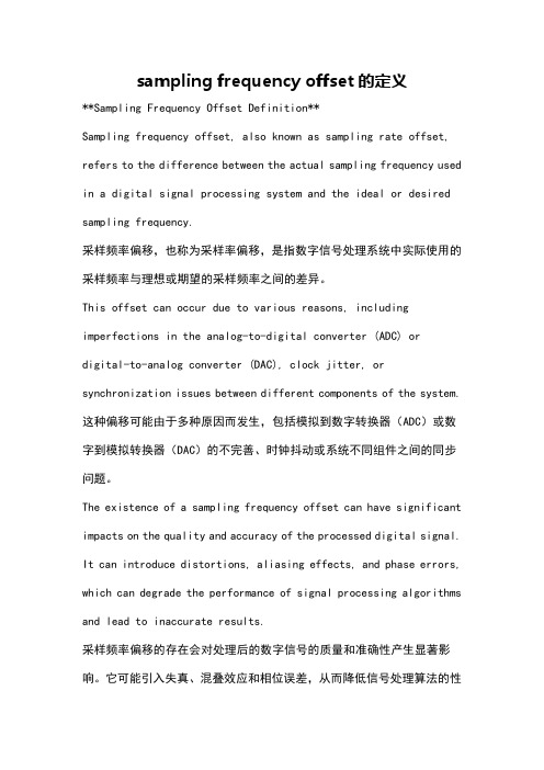
The proposed system reduces the false alarm rate and improves the detection probability for high velocity UEs. An optimized receiver utilizes also the correlation values in the frequency cyclic shift pairs in addition to those in the delay window. Such an algorithm is explained in the Appendix B and used for comparing the restricted 0.8 ms signatures and repeated 0.4 ms signatures in Figs. 2 and 3. Non-coherent combining over the repeated 0.4 ms sequences was used. Simple one-path LoS channel is assumed and frequency offset is set to twice the Doppler frequency. Thus, frequency offsets of 440 Hz, 880 Hz, and 1360 Hz correspond to 120 km/h, 240 km/h, and 360 km/h UE speeds, respectively, when a carrier frequency of 2 GHz is assumed. False alarm rate over 1 means that more than one preamble out of 64 are wrongly detected on average. The proposed scheme provides significant gains in the considered case. The gains are even larger if compared to 0.8 ms sequence without cyclic shift limitations.
- 1、下载文档前请自行甄别文档内容的完整性,平台不提供额外的编辑、内容补充、找答案等附加服务。
- 2、"仅部分预览"的文档,不可在线预览部分如存在完整性等问题,可反馈申请退款(可完整预览的文档不适用该条件!)。
- 3、如文档侵犯您的权益,请联系客服反馈,我们会尽快为您处理(人工客服工作时间:9:00-18:30)。
3GPP TSG RAN WG1 #49R1- 072107Kobe, May 7 – 11, 2007Source: Marvell SemiconductorTitle: On ZC-based PSC and Frequency OffsetAgenda Item: 7.2Document for:Discussion1. IntroductionIt was agreed in the RAN1#48bis meeting that the P-SCH design is based on ZC, and that it has no repetitive structure in the time domain. Some companies expressed concern about the performance of initial sync with such design because of possible frequency offset (FO). In this contribution we show why a ZC-based PSC is indeed problematic for initial sync and propose to reverse RAN1 decision, and design the PSC based on PN-QPSK or a combination of several ZC sequences (e.g. theinterleaved ZC structure proposed by Motorola [2]). Alternatively, the following analysis and simulations suggests how to choose the least problematic ZC index-triplet for the P-SCH.2. AnalysisThe source of the problem is in an approximate ambiguity between frequency and time shifts. This ambiguity can be demonstrated by the simple case of a one-subcarrier (15 kHz in the EUTRA configuration) shift, in which casePhaseL uk j k ZC k ZC L u j L uk j L uk j L k u j k ZC L ukj k ZC LLL L⨯-⨯=+⇒-⨯-⨯-=+-=+-=)/2exp()()1()/2exp()/2exp()/exp()/)1(exp()1()/exp()(222ππππππI.e., the frequency shift is equivalent to a multiplication by a rotating phase exp (-j2πuk/L ), which, for the time domain sequence (S=IFFT(ZC)) translates into an approximate cyclic time shift by u samples. The ambiguity is only approximate because the above relation does not hold for the full series over all k – there will be a missing first element and an extra last element. Note that this time-frequency ambiguity is true not only for the even-L ZC sequence in the above example, but also for odd-L ZC sequences (for odd L , ZC =exp (-j πuk (k+1)/L )).Now, suppose the signal to be detected is 15kHz off, and we use an ML hypothesis-testing detector to detect it bycorrelation with all possible frequency-shifted versions of the time domain sequence S. Then, the received signal will have a maximal correlation with the 15kHz-shifted S at the correct time, but it will also have a significant correlation with a non-frequency-shifted sequence, at a different timing which is u samples away from the correct timing. Thus, in the presence of noise the detector might err and detect the signal in the wrong time and the wrong FO.The above approximate time-frequency ambiguity is manifested also when having FO’s smaller than one subcarrier, and when using a partial-correlation detector [3] followed by FO estimation derived from the phase-rotation of the partial-correlation over the two segments. For example, Figure (1) shows the two-segment correlation of the time-domain PSC symbol generated from a frequency-domain ZC sequence with L =64 and index u , with a received signal generated by frequency-shifting the PSC.2-seg Corr, u=3, FO=5kHz2-seg Corr, u=23, FO=10kHzFigure 1: Two-segment partial correlation between a PSCH symbol generated from a FD ZC sequence with L=64, and a frequency-shifted replica. (a) ZC index u=3 and FO=10kHz, (b) u=3 and FO=5 kHz, (c) u=23 and FO=10 kHzIn 1(a) and 1(b) the peak at sample 64 corresponds to the correct time and correct FO, while the peak at 67 (=64+3)corresponds to a false time detection and (false) zero FO. The relative magnitude of the false peak increases with increasing FO. Thus, with large FO segmental correlation detector will generate false timing and false FO estimation with significant probability. In 1(c) with u=23 the false peak at sample 87 (=64+23) is lower than the false peak with u=3; Thus, this index will have a higher probability for correct detection.The time-frequency ambiguity is also manifested in the “reverse” scenario, where the FO is zero but the received signal is composed of multipath-delayed reflections. Suppose that the strongest reflection is detected at the correct time, but there is another reflection which is delayed by u samples relative to the detected reflection. This 2nd reflection appears to the FO estimator (operating at the 1st reflection timing) as a frequency-shifted PSC, and will therefore generate a false frequency offset component. This multipath-FO ambiguity will appear as long as the channel delay spread is larger than the time span of u samples. Thus, large values of u will not have this degrading effect 1.In Figure (2) we plot four performance measures as a function of the ZC index. The analysis is performed with a P-SCHsymbol generated from a ZC sequence of length 64, mapped to the center 64 subcarriers of a 128-subcarrier symbol, with the DC punctured, and frequency-shifted by 10 kHz. A corresponding PSC replica is generated with and without the FO. The performance measures are as follows:1. PAPR of the time-domain PSC symbol2. Relative autocorrelation of the non-FO PSC symbol: maximal side-lobe divided by the main-lobe3. Cross correlation: The ratio between the peaks of the cross correlations with the FO and non-FO replicas. This ratiois indicative of the probability of false FO detections with an ML hypothesis-testing detector. 4. Two-segment correlation and FO estimation with the non-FO replica: The ratio between the false peaks (like those at67 in Figure 1(a) and 87 in (c)) to the correct ones (like the one at 64). From Figure 2 we observe that the time-frequency ambiguity effect is manifested by the large ratios of false/true peaks in both the ML and two-segment Xcorr detectors. However, the effect is reduced in the center values of the ZC index.051015L=64, Nfft=128, df=10kHz, CP=9ZC indexFigure 2: SCH-detection performance measures for ZC-based PSC, L=64, assuming Fs=1.92 MHzThe analysis is repeated in Figure 3 with a 2x downsampling, corresponding to 0.96 MHz sampling rate at the receiver. Here a worst-case scenario is assumed, corresponding to the case where the true timing falls on a half-chip phase while the competing false detection occurs at a perfect sampling phase. The analysis is also repeated in Figure 4 for an odd ZCparameter L =73 and a sequence length of 72 subcarriers. We observe the same time-FO ambiguity and index-dependence in all cases.-25-20-15-10-5051015L=64, Nfft=64, FO=10kHz, CP=4ZC indexFigure 3: SCH-detection performance metrics for ZC-based PSC, L =64, assuming Fs=0.96 MHz and worst-case samplingphase01020304050607080510L=73, Nfft=128, FO=10kHz, CP=9ZC indexFigure 4: SCH-detection performance metrics for ZC-based PSC, L =73, assuming Fs=1.92 MHz3. Choosing 3 PSC sequences based on ZCBased on the above analysis, the three PSC sequences for EUTRA should be chosen according to the following criteria:1.Smallest (relative) segCorr false peaks, which prefers ZC indexed around the center (e.g., 31 in the L=64 case)2.Due to the multipath-FO ambiguity, it is preferred to use a ZC index u which correspond to delay (u samples at 0.96MHz sampling rate) that is larger than the maximal expected delay spread. Assuming this maximal delay spread to be around the extended CP duration (16 usec), the index u should lie between 16 and 48.3.Smallest autocorrelation side-lobe, preferring ZC indexes around the edge (e.g., 1)4.Smallest PAPR, preferring a set of indices which have, say, PAPR < 5dB5.Smallest cross correlation between the 3 PSC sequences. An empirical cross correlation analysis shows that thisrequirement leads to a preference of having the distance between the indicees of the 3 sequences being either odd, or equal to 2. I.e., if two out of the three indices are denoted by u i and u j, the distance d ij= u i–u j is either equal to 2 or an odd number (see, e.g., Figure 5)xcorr(psc(31,64),psc(i,64))iFigure 5: Peak Xcorr between PSC based on ZC #31 to all 64 ZC-based PSCThe requirements for small autocorrelation side-lobe and small FO ambiguity are conflicting. When FO estimation is not needed (such as in neighbour-cell search) the preference would go for the small or large indices such as 1 and 63. However, when FO estimation is needed (such as in initial cell search) these indices would fail colossally. In contrast, satisfying the FO requirements should not hurt the neighbor cell search that much: neighbour-cell search is expected to perform at SNR down to around -6 dB, and thus it is expected to perform reasonably well also with the -10 dB autocorrelation side-lobes of the middle ZC indexes. Thus, our preference is an index triplet such as (29,30,31) for the L=64 and L=73 designs, which is most robust to FO, has good enough autocorrelation, has good cross-correlation properties, and low PAPR.4. Pseudo Random QPSKFigures 6-7 show the same analysis as Figures 2 and 5 but for 64 frequency-domain PN QPSK sequences. The PAPR and peak Xcorr are slightly less favorable than those of the ZC sequences, but there is no time-frequency shift ambiguity and hence no FO problem.051015L=64, Nfft=128, FO=10kHz, CP=9ZC indexFigure 6: SCH-detection performance metrics for FD PN-QPSK PSC1xcorr(psc(31,64),psc(i,64))iFigure 7: Peak Xcorr between PSC based on PN-QPSK #31 to all 64 PN-QPSK-based PSC5. Cell Search SimulationFigure 8 show initial and neighbor-cell search detection probabilities for 4 PSC designs:1. FD ZC, L =64, indexes 29,30,312. FD ZC, L =64, indexes 1,23,43, proposed in [1] by Nokia3. FD ZC, L =73, indexes 29,30,314. PN-QPSK, three sequences selected at random5. Interleaved ZC as proposed in [2]: Two 32-long ZC sequences with parameter L =31 and repetition of the 1st element,and with a triplet of index pairs (1,2), (3,30), (29,28). In the figure-legend the index pairs are denoted by u =31x Id1+Id2. The simulation conditions are listed in Table 1. In these simulations the difference between initial and neighbor cell search is in the assumption on FO: In the “neigh bor-cell” configuration it is assumed there is no FO, so a full -correlation detector is used and no frequency correction is applied. There is no handling of neighbor lists, and ideal verification is assumed.-10-8-6-4-2240.10.20.30.40.50.60.70.80.91TU3 BW=5 FO=0 kHz NeibrSrch SSC =WALSH NumGrpIDs = 676SINRD e t e c t P r o b(a)-10-8-6-4-22400.10.20.30.40.50.60.70.80.91TU3 BW=5 FO=0 kHz InitSrch0 SSC =WALSH NumGrpIDs = 676SINRD e t e c t P r o b-10-8-6-4-202400.10.20.30.40.50.60.70.80.91TU3 BW=5 FO=10 kHz InitSrch10 SSC =WALSH NumGrpIDs = 676SINRD e t e c t P r o bFigure 8: Cell ID detection probability: (a) neighbor cell search, (b) initial search with FO=0, (c) initial search, FO=10 kHz(b)(c)6. DiscussionThe PSC based on ZC with L=64 and index u=1 proposed in [1] as part of the triplet (1,23,43) performs poorly at initial search. With small FO this is due to erroneous FO estimation in the multipath channel. With large FO the additional effect of erroneous timing and FO estimation makes it fail completely. The index triplet (29,30,31) performs at initial search significantly better than (1,23,43).The L=73 (72 subcarriers) and L=64 (64 subcarriers) perform equally. (Note that all the OFDM symbol energy is allocated to the SCH subcarriers).Interleaved ZC proposed in [2] performs in initial search better than any of the ZC sets. Frequency-domain (FD) PN-QPSK performs similar to Interleaved ZC. We note, however, that we did not make a conclusive search on all possible QPSK sequences, and thus it might be that even better-performing sequences can be found.We conclude that the optimal PSC design can be equally well based on either PN-QPSK or the Interleaved ZC. Alternatively, a carefully chosen ZC index triplet produces only a small loss in initial search. One such set for either the L=64 or L=73 designs is the index triplet (29,30,31).References[1]R1-071659, “Selection of PSCH Sequences”, Nokia, RAN WG1 #48bis, St. Julian’s, Malta, 26 – 30, Mar, 2007[2]R1-0xxxxx, “ZC Sequence Based P-SCH Design Using No-Repetitive Structure”, Motorola, RAN WG1 #49, Kobe, 7 –11 May, 2007[3]R1-061187, “Comparison on Cell Search Time Performance between SCH-Replica Based and Auto-Correlation BasedDetections in E-UTRA Downlink”, NTT DoCoMo, Fujitsu, Mitsubishi Electric, NEC, Panasonic, Toshiba Corporation, RAN WG1 #45, Shanghai, China, 8 – 12 May, 2006。