韩国韩端机器人介绍
nachi+那智机器人资料

提供丰富的外设接口,如USB、HDMI等 ,方便用户连接各种外部设备和扩展功能 。
03
使用指南
安装与设置
安装步骤
打开包装,检查机器人各部件是 否齐全。 按照说明书指示,连接机器人与 电源。
安装与设置
• 下载并安装相关软件,以便于后 续操作。
安装与设置
设置指南
根据个人需求,调整机器人的各项参数, 如工作模式、速度等。
问题2
那智机器人移动不顺畅
解答
可能是由于电量不足或机械部件故障。请确保电池已充 电,并检查所有机械部件是否正常工作。
问题3
那智机器人无法识别障碍物
解答
请检查周围环境是否明亮,并确保障碍物不是透明或与 机器人颜色相近。同时,更新机器人固件或软件可能有 助于解决问题。
技术支持与联系信息
电话支持
拨打机器人包装盒上的技术支持电话,获得实时 帮助和指导。
根据实际使用情况,适时更换易损件和损 耗件。
维护与保养
01 维修与保养提示
02
若遇到无法解决的问题,请联系专业维修人员进行检
修。
03
不要自行拆卸机器人内部结构,以免造成损坏或安全
事故。
04
常见问题与解决方案
常见问题解答
问题1
那智机器人无法启动
解答
请检查电源是否正常,并确保电池已充满电。如果问题 仍然存在,请联系技术支持。
在线支持
访问那智机器人官方网站,查找常见问题解答、 在线论坛和教程等资源。
邮件支持
发送邮件至那智机器人技术支持邮箱,描述您的 问题和详细情况,以便得到及时回复。
产品更新与升级
软件更新
定期检查并安装机器人软件更新,以确保最佳性能和 安全性。
【推荐下载】现代工业智能机器人在焊接领域的广泛应用

张小只智能机械工业网
张小只机械知识库现代工业机器人在焊接领域的广泛应用
焊接机器人是指从事焊接的工业机器人,包括切割与喷涂。
英文名:weldingrobot,工业机器人是一种多用途的、可重复编程的自动控制操作机,具有三个或更多可编程的轴,用于工业自动化领域。
为了适应不同的用途,机器人最后一个轴的机械接口,通常是一个连接法兰,可接装不同工具或称末端执行器。
焊接机器人就是在工业机器人的末轴法兰装接焊钳或焊(割)枪的,使之能进行焊接,切割或热喷涂。
韩国现代重工生产的的焊接机器人
随着电子技术、计算机技术、数控及机器人技术的发展,无锡丹佛数控装备机械科技有限公司提供的韩国现代自动焊接机器人系统集成工作站,从80年代开始用于生产以来,其技术已日益成熟,主要有以下优点:
1)稳定和提高焊接质量;
2)提高劳动生产率;
3)改善工人劳动强度,可在有害环境下工作;
4)降低了对工人操作技术的要求;
5)缩短了产品改型换代的准备周期,减少相应的设备投资。
因此,在各行各业已得到了广泛的应用。
焊接机器人组成
焊接机器人主要包括机器人和焊接设备两部分。
机器人由机器人本体和控制柜(硬件及软件)组成。
而焊接装备,以弧焊及点焊为例,则由焊接电源,(包括其控制系统)、送丝机(弧焊)、焊枪(钳)等部分组成。
对于智能机器人还应有传感系统,如激视觉系统及其控制装置等。
BIP-7000 韩国蓝鸟

大小(宽×长×高) 重量 显示屏 触摸屏 键盘 标准电池 大容量电池 扩展插槽 用户识别码插槽 音响 摄像头 全球定位系统
处理器 操作系统 内存 界面
操作温度 库存温度 防湿 落地测试 防震/防尘/水参数
WWAN RADIO WLAN RADIO WPAN RADIO
条码
规格
72 毫米×196.7 毫米×33.6 毫米/2.8×7.7×1.3inch 包括标准电池:306 克/包括大容量电池:326 克 2.8QVGA with back light, TFT Touch Window LCD,260K,240×320
超市商场
销售团队自动化降低运行成本迅速提高销售额以利益最大化。使用带刷卡功能 的手持 POS 系统可改善客户服务。另外,直接从客户现场访问大型 CRM 数 据库可实现对关键客户操作的移动式指导与商机管理。销售经理通过分析采购 模式和客户的要求可以管理库存信息和拟定营销策略。
蓝鸟 BIP-7000 手持数据采集终端参数配置
Windows Mobile 6.5/Windows CE 5.0
128MB RAM(up to 256MB)/256MB ROM(up to 512MB)
RS232C,USB1.1 Host &Client 使用环境
-20℃ to 55℃/-4℉ to 131℉ -30℃ to 70℃/-22℉ to 158℉
在政府/公共部门,让该领域的流程更为规范简明,由此可提高公共机构的服务 水平,降低其成本。能够应付紧急情况,及时紧急报告和实时处理大火和洪水 情况。此外,还具有其他功能,处理罚款逃税罪犯,收集的证据在事故现场相 机的功能。
公共交通部门
在公共交通部门,例如出租车、公共汽车、火车、轮船或航班它可以帮助你快 速准确确认售票、发车时间,与全球定位系统功能,它使你能够有效控制运输 路线和协调服务区间。移动计算技术主要包括无线网络和手持终端的技术。要 保证货物即时供应,必须实现实时记录数据,缩短信息与实物发生中的时间差, 真实地反映整个运输过程。
韩国韩端机器人介绍
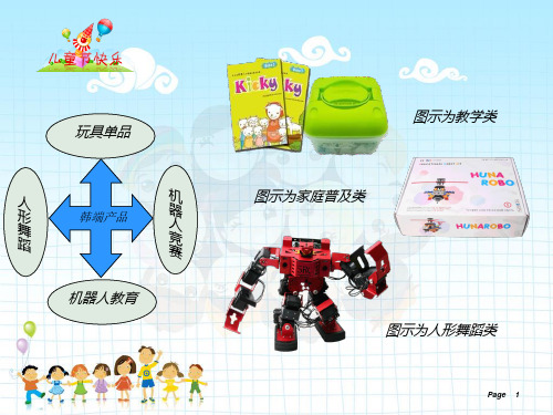
图示为教学类
人 形 舞 蹈
韩端产品
机 器 人 竞 赛
图示为家庭普及类
机器人教育 图示为人形舞蹈类
Page
1
宝乐、CLASS、TOP
校外培训班或学校,幼儿园
韩 端 科 技 产 品
人形舞蹈机器人
学校及公司展览
FUN&BOT系列
超市 玩具店 家庭
韩端产品消费群分布图
Page
2
韩端产品体系 1、教育用机器人 5-7岁用---宝乐系列(含初级、中级)
Page
18
Page
5
2、玩与学并进
玩中学,学中玩,玩中智是我们提倡的一种教育方式,通过游戏让孩子学习,通过 学可以让玩变得更有层次,在玩中收获智慧。 课程主要是通过讲解机器人知识、了解课程内容、进行动手搭建及编程到最后的调 试运行。 我们每节课都会设置一个比赛,比赛的意义是我们通过比赛让孩子们了解自己机器 人的性能,让他们明白自己的问题出在哪里,学会发现并解决问题。
Page
6
3、独具特色的六面体积木结构
韩端自主专利的积木结构保证我们的积木拥有超强的拓展性,相比较市面流行的上 下颗粒的积木结构,我们可以完成上下、前后、左右的一个立体搭建过程
Page
7
4、良好的售后保障及价格体系
韩端教育机器人产品都采取自主研发,生产,销售。有独立的生产工厂为韩端教育 产品注入活力,我们提供零件丢失补充服务,零件损坏补充服务,零件更新升级服务。 让我们的消费者可以放心的使用,并保障孩子们可以在享受到机器人带来的乐趣。让丢 失零件不在成为负担。
7-10岁用---好伙伴系列(含初级、中级编程、高级编程)
Page
3
10-13岁用---高手系列(含初级、中级)铝制材质,原装韩国进口
服务员机器人发展史

- 2003年,韩国将服务机器人作为国家经济增长点
国家层面大力支持,推动服务机器人产业发展
- 2010年代,服务机器人广泛应用于酒店、餐饮等行业
服务员机器人成为提升服务质量、降低人力成本的重要手段
- 机器人技术不断创新,如仿生技术、柔性化、AI分析与理解能力等
机器人形态、功能和控制方式不断进化,向更高智能化发展
发展期(20世纪中后期)
- 1984年,约瑟夫开发服务机器人Helpmate
专为医院设计,实现送饭、送药及送信等功能
- 1988年,日本东京电力公司研发巡检机器人
自主规划服务机器人技术逐步成熟,开始应用于特定场景(如医院、酒店)
机器人技术逐步向实用化、智能化发展
- 2024年政府工作报告提出加快发展新质生产力,开展“人工智能+”行动
政策支持进一步推动服务机器人产业的发展
服务员机器人发展史
时间段
关键事件/里程碑
主要特点/影响
萌芽期(17世纪-20世纪初)
- 1662年,日本竹田近江发明自动机器玩偶
早期尝试,基于机械原理的简单自动化
- 1738年,法国杰克发明机器鸭
多功能自动化玩具,展示基本机械运动能力
- 1927年,美国西屋电气公司发明“电报箱”机器人
初步实现机器人与人交互,通过无线电发报机回答问题
哈佛大学研发出新型柔性机器人

行业动态News9Robot Technique and Application20182行业动态(新技术)近日,哈佛大学的研究人员以日本古老的剪纸艺术kirigami 为设计灵感,利用蛇鳞结构的“各向异性摩擦特性”研发出一种充气式柔性机器人。
该机器人能够像蛇一样,通过充气与放气的循环动作来实现爬行,可用于探索危险地形,进行勘探或执行搜索救援等任务。
这款机器人实现运动的关键在于“皮肤”。
为了制造与蛇鳞类似的鳞片皮肤,研究人员制作了各种可伸缩的塑料片,并尝试了多种不同的切口形状,且每一片鳞片都通过激光蚀刻技术刻上独特的图案,然后再将该片材缠绕在可膨胀与放气的硅胶管周围。
这种结构使得机器人在躯体膨胀并拉伸鳞片材料时,原本平均的鳞片会变形并从机器人体内弹出进而抓住地面,并将躯体的反复膨胀转化为向前运动。
为找到最佳的鳞片切割模式,研究人员通过比较线条、梯形、三角形以及圆形等不同的比例模型,发现梯据悉,韩国首尔大学研发出能够依靠吸收周围环境中水分而前行的微型机器人。
该机器人可以爬行、蠕动,并像蛇一样弯曲。
这种微型机器人的设计灵感来自于植物,其可以通过吸收地面或空气中的水分来改变自身形状和大小。
研究人员通过模仿非洲的灌木植物“枯野葵种子的鬃毛”,利用纳米纤维制作成该微型机器人,并将其分成两层:一层用来吸收水分,另一层则不吸收水分。
当机器人置于潮湿的表面上时,吸湿层膨胀,从而使机器人弓起;机器人一旦2月7日,广州云从信息科技有限公司(以下简称云从科技)正式宣布推出3D 结构光人脸识别技术。
据悉,这是中国企业首次将结构光技术应用在人脸识别系统上,标志着中国突破了结构光人脸识别技术的壁垒。
3D 结构光人脸识别系统基于“飞龙II”深度学习结构光算法与3D 结构光深度摄像头,不仅能够利用结构光设备同时获取场景中的彩色、红外、深度图片,而且还能对场景中的人脸进行检测分析,形成3D 人脸图像。
该人脸识别技术具有3大优势:用户只需在摄像头前被捕捉到面部画面,不需要进行其他动作配合,即可完成生物活性验证,有效应对纸张、面具、手机屏幕等各类道形鳞片最适合这款机器人,因为梯形能够让鳞片充分伸展,从而帮助机器人在膨胀自身躯体时得以产生更长的“步幅”。
大锤机器人知识点总结
大锤机器人知识点总结大锤机器人是一款由科技公司开发的智能机器人,具备多种功能和特点。
下面将从机器人的外观、功能、应用领域以及未来发展等方面进行详细总结。
一、外观特点大锤机器人外观设计独特,采用了现代科技感十足的金属外壳,给人一种高端大气的感觉。
机器人的身高大约为1.5米,体积适中,便于携带和移动。
它的头部设计为一个可旋转的球形,内置了高清摄像头和麦克风,可以实时感知周围环境。
二、功能特点1. 语音交互:大锤机器人内置了先进的语音识别和语音合成技术,可以与人进行自然对话。
用户可以通过语音指令控制机器人的行为,例如播放音乐、讲故事、查询天气等。
2. 智能导航:大锤机器人内置了多个传感器和地图导航算法,可以自动识别室内环境并规划最优路径。
它可以自主移动,避开障碍物,并准确到达目的地。
3. 人脸识别:大锤机器人配备了高精度的人脸识别系统,可以准确辨认人脸信息。
它可以通过人脸识别技术实现身份认证、人员统计等功能。
4. 智能家居控制:大锤机器人可以连接到智能家居设备,通过语音控制实现家居设备的开关、调节等操作。
例如,可以通过语音指令让机器人打开电视、调节空调温度等。
5. 智能安防监控:大锤机器人内置了高清摄像头和智能图像识别算法,可以实时监控室内环境。
当机器人发现异常情况时,会立即向用户发送通知。
三、应用领域1. 家庭助理:大锤机器人可以成为家庭的智能助理,帮助用户管理日程、提醒事项、播放音乐等。
它还可以与家庭成员进行互动,提供娱乐和休闲服务。
2. 教育培训:大锤机器人可以用于教育培训领域,例如儿童早教、语言学习等。
它可以通过互动对话和游戏等方式,帮助儿童提高学习兴趣和能力。
3. 商业服务:大锤机器人可以应用于商业场景,例如餐饮服务、导购助手等。
它可以提供菜单推荐、商品介绍等服务,提升用户体验和销售效果。
四、未来发展随着人工智能技术的不断发展,大锤机器人的功能和应用领域还将不断扩展。
未来,它可能具备更强大的计算能力和学习能力,能够更好地理解人类的需求,并提供更个性化、智能化的服务。
心脏外断电机器人DDU-100系列产品说明书
Product Features • TYPE: Semi-automatic external defibrillator • MODEL: DDU-100A, DDU-100E • WAVEFORM: Biphasic Truncated Exponential (Impedance compensated)• ENERGY : Adult: 150 Joules / Pediatric: 50 Joules / (Nominal into 50 Ohm load)• CHARGE TIME**: DBP-2800: Less than 6 seconds DBP-1400: Less than 9 seconds • VOICE PROMPTS: Extensive voice prompts guide user through operation of the unit and CPR • CPR PACING: Metronome • CONTROLS: Lighted On/Off buttoNLighted Shock button • INDICATORS: “check pads” / “do not touch patient” / “analyzing” / AED Status LEDDimensions and Weight • SIZE: 8.5 x 11.8 x 2.7 inches (22 x 30 x 7 cm) • WEIGHT (Approximate):• With DBP-1400: 4.2 lbs (1.9 kg)• With DBP-2800: 4.4 lbs (2.0 kg)Defibrillator / Monitoring Pads:• Model: Adult – DDP-100 / Child/Infant – DDP-200P • Type: Pre-connected, single-use, non-polarized, disposable, self-adhesive electrodes with cable and connector • Surface Area: 103 cm2 (nominal, each pad) / 50 cm2 (nominal, each pad)• Pad Placement: Adult – Anterior/Anterior Child/Infant – Anterior/Posterior • Cable Length (typical): 48 in. (122cm)Call your local US Med-Equip representative or 877-677-7767 today for more information.Defibtech LifeLine AEDDefibrillator Product photo may include optional features.The Lifeline AED is a semi-automatic defibrillator that is technologically advanced enough to include all mission critical features necessary to provide the most advanced treatment for Sudden Cardiac Arrest. Yet is so simple and unintimidating to use that even non-medical personnel can effectively save lives. The Lifeline AED has a simple two button user interface, clear, calm voice prompts, brightly lit progress lights and actively illuminated status indicator. The Lifeline AED has a roomy handle and rubberized surfaces.The Lifeline AED is sold as part of the DCF package, which includes the following:• DDU-100 Lifeline AED • DCF-200 Five-Year Battery Pack or DCF-210 Seven-Year Battery Pack (both with 9V Batteries)• DDP-100 Adult Defibrillation PadsThe Lifeline AED supports current AHA and ERC Resuscitation Guidelines.。
Development of Humanoid Robot Platform KHR-2 (KAIST Humanoid Robot - 2)
Development of Humanoid Robot Platform KHR-2 (KAIST Humanoid Robot - 2)Ill-Woo Park, Jung-Yup Kim, Seo-Wook Park, and Jun-Ho OhDepartment of Mechanical Engineering,Korea Advanced Institute of Science and Technology (KAIST),373-1 Guseong-dong, Yuseong-gu, Daejeon, 305-701Republic of Korea{mrquick,kirk1,seowook.park,junhoh}@mclab3.kaist.ac.krThe mechanical and electrical system designs and system integration including controllers and sensory devices of the humanoid KHR-2 are presented. The design concept and the objective are also discussed. Since last year (2003), we have been developing KHR-2, which has 41 DOF (degrees of freedom). Each arm of KHR-2 has 11 DOF in total that amounts to 5 DOF/hand (i.e. fingers), 2DOF/wrist, and 4 DOF/arm. Each leg constitutes 6 DOF. Head constitutes 6 DOF (2 DOF for eyes and 2 DOF at the neck), and trunk has 1 DOF. KHR-2 has been mechanically designed to have a human friendly appearance and also wide ranges of angular motions. Its joint actuators have been designed in order to reduce motion uncertainties such as backlash. All axes of KHR-2 are under the distributed control, which reduces the computation burden on the main controller (PC) and also to facilitate device expansions. We have developed a microprocessor-based sub-controller for servo motor operations, onto which sensory feedback is interfaced. The main controller (PC), which is mounted on the back of the robot communicates with sub-controllers in real-time through CAN (Controller Area Network). Windows XP is used as the OS (Operating System), which enables rapid program development. RTX (Real Time eXtension) HAL extension software is used to realize the real-time control in Windows XP environment.KHR-2 has several sensor types such as 3-axis F/T (Force/Torque) sensors at foot and wrist, inertia sensor system (accelerometer and rate gyro) and CCD camera. The F/T sensor at the foot is crucially important for stable walking. The inertia sensor system is essential to determine the inclination of the robot with respect to the ground.Keywords: Humanoid robot, KHR-2, biped locomotion.1. IntroductionThe research in humanoid robots is now on its way of diverging into various categories. The research on such areas as artificial intelligence, robot hardware development, realization of biped locomotion, and interaction with the environment are gaining a rapid phase of development with the help of the rapid growth of technology. The research on humanoid robotics has gained a particular interest in this new phase as humanoids tend to change the concept of the robot. In the past, robots were confined to the industry carrying out such jobs as welding, and parts-assembly (automobile and electronic devices) in that the objectives, specification and optimal design parameters were clearly defined with concern to the economic aspects, productivity and efficiency. As the economical paradigm is changing from mass production to small quantity batch production, people’s concept of the robot has been gradually diverging. By today, it has come to a situation, where the robot should be able to perform a wide variety of functions that helps people in their daily life.Recently, many researches have been focused on a development of humanoid biped robot that looks similar to a human being. Honda R&D’s humanoid robots[1], WABIAN series of Waseda University[2], ASIMO[3], H6 & H7[4], HRP[5] and JOHNNIE[6] are well known human size humanoid biped robots. Since the humanoid biped robot is very complicated, expensive and unstable, it is very difficult to realize a real-time motion control based on the sensory feedback similar to human behavior.The objective of this project is to develop a reliable humanoid platform which allows the implementation of various theories and algorithms such as dynamic walking, human interaction, AI (Artificial Intelligence), visual & image recognition, and navigation. We used Windows XP as the OS, which is the most familiar OS to design, implement, and maintain those theories easily. The mechanical parts have been designed to have simple shapes that can be easily machined by the 2-D process. The electrical system was designed with concern to easy upgrading, replacement, and reprogramming.The ZMP equation of the humanoid can be simplified to find a useful relationship between robot’s natural frequency and size, which says that if the size of the robot is small, the natural frequency is high, and vice versa. Finding the optimal size of the robot is a different research problem. The actuator specifications such as power, torque, and speed were investigated in KHR-0[7]. KHR-0 which was developed in 2001 has 2 legs without upper body. Based on KHR-1[8] design, we designed KHR-2, the latest version of KHR series. Compared to KHR-1, KHR-2 is different in size, and it has updated designs in the mechanical and electrical systems. In mechanical design, the joint stiffness and the movable joint angle ranges have been improved, and its appearance has become more human-like and human friendly. It has hands, head and neck, eyes, and fingers. In electrical design, control hardware system has changed from centralized control in that the joints are directly controlled by the main PC, to decentralized control through CAN communication protocol. While developing the platform of KHR-2, walking control algorithm has been studied on the KHR-1 platform.2. KHR-2: KAIST Humanoid Robot – 2Fig. 1. Humanoid Robot KHR-2KHR-2 shown in Fig. 1 is a new humanoid robot platform. The height is 1.2m and the weight is 56Kg. Its design concepts are human-like shape, stiff joints with no backlash, self-contained controller system, and simple kinematics. We wanted to make it to have a human-like appearance, wide motion capability, and adequate number of degrees of freedom (DOF) to perform human-like motions. Using harmonic drive reduction gear, we designed backlash free joints. Its joint controller, motor drive, battery and main controller (PC) are installed in the robot itself. KHR-2 has simple kinematics by crossing the joint axis in the shoulder, wrist, hip and ankle joint. Windows XP and RTX provide many references for developing the hardware and software, and it is a convenient programming environment for the KHR-2. The specifications of KHR-2 are given in Table 1.Table 1. KHR-2 specificationsResearch term 2003~Weight 56KgHeight 1.2mWalking Speed 1.0Km/hWalking Cycle 0.95sec Fixed Cycle, 52cm Fixed StrideGrasping Force 0.5Kg/fingerActuator Servo motor + Harmonic Speed Reducer+ Drive UnitControl Unit Walking Control Unit, Servo Control Unit,Sensor Communication Unit,Communication UnitFoot 3-Axis Force Torque SensorSensorsTorso Rate Gyro & Inclination SensorBattery (Ni-H)24V/8AH (192Wh), 12V/12AH (144Wh) PowerSection ExternalPower 12V, 24V (Battery and External Power Supply Changeable)Operation Section Keyboard, Mouse, Wireless LANOperating System (OS) Windows XP and RTXTotal Degree of Freedom 41 DOF3. The KHR-2 Design: Concepts and ObjectivesIn this section, we introduce the concepts and objectives of the KHR-2 design. As briefly mentioned above, there are four design concepts as follows.(1)Human like shape and movement(2)Negligible uncertainty of actuators – Stiffness and no backlash(3)Self-contained system(4)Simple kinematics3.1 Human like shape and movementBeing human-like refers to two concerns: The human-like appearance and human-like motion. Regarding the first, the appearance of the robot should consist of both human and robot characteristics. The second, the robot should be able to imitate the human movements. To be human-like, a humanoid robot needs to have an adequate number of DOF, sufficient power, and wide ranges of joint motions.3.2 Negligible uncertainty of actuatorsThe major joints such as all the joints of legs should be robust. In other words, the output side of the major joint should have a negligible motion uncertainty such as backlash and noise. This is the reason why harmonic drive reduction gears are used in the joints such as legs, arms and trunk. Moreover, the motor drive units such as servo controllers and amplifiers are mounted close to the actuators to reduce cable noise. It is important to design reliable actuators as actuator uncertainty could destabilize the robot system.3.3 Self-contained systemThe main controller, servo controller units, sensor units and batteries are stored inside the robot to accomplish autonomous movement and human-like appearance. It further makes KHR-s free of having a backpack. The robot should be able to be operated remotely through wireless LAN using a portable PC. In the future, using the wireless protocol, we may be able to operate the robot by various kinds of devices that are operable with wireless LAN modules.3.4 Simple kinematicsThe robot joints have been designed to have simple kinematics. By intersecting the joint axes such as hip (3-axis), ankle (2-axis), shoulder (3-axis), and wrist (2-axis), a simple closed form inverse kinematics solution has been created [10]. In this closed form solution, trigonometric functions such as sin() and cos() are involved, but no Jacobean inverse involved. Therefore, path generation and controller design became simple4. Mechanical DesignThe mechanical design concerns the cost, development time, wiring, and movable joint angle ranges in particular. Mechanical design should concern the convenience of manufacturing the robot, therefore, 3-D manufacturing process such as die casting, CNC machining have been avoided to reduce development time, maintenance, and cost. Only 2-D machining process such as turning, milling, wire cutting and drilling processes have been considered.There is lot of wiring in the robot. Communication cables, power supply cables (which are used in controllers and actuators), and sensor signal cables should have organized paths with proper tradeoffs between moving joint paths, good appearance, line length, etc. To make the wiring as simple as possible, cable paths were designed to go through the center of joint axes. And, length was shortened using small slacks.Table 2 lists up the 41 DOF of KHR-2. There are 12 DOF in legs for walking and 19 DOF are in the upper body. Hand mechanism has 7 DOF/hand, 1 DOF/finger and 2 DOF/wrist. It has 5 fingers in hand. Head mechanism has 6 DOF, 2 DOF/eye and 2 DOF at the neck. The eyes have been designed to move independently so that to perform visual image tracking and stereo vision. Torso has 1 DOF in yaw axis for compensation of yaw moment when the robot walks. Table 3 shows the joint angle ranges. A wider range of angular motions are used in KHR-2 joints that makes it capable of performingwalking, running, as well as various other human-like movements such as sitting down on a chair and floor, and crawling on the ground. It enables other features of KHR-2, such as being able to sit in the car to take a ride with its human companion. As a matter of fact, a wider range of movable joint angles allows a robot platform to extend its application area.Table 2. Degree of Freedom (DOF) of KHR-2Head Torso Arm Hand Leg Total2 Neck 2/Eye (pan & tilt)1/Torso Yaw 3/Shoulder1/Elbow5/Hand2/Wrist3/Hip1/Knee2/Ankle6 DOF 1 DOF 8 DOF 14 DOF 12 DOF 41 DOFTable 3. Movable Angle Range of Lower Body JointJoint Movable angle rangeRoll -90 to +38°Pitch-90° to +90°HipYaw -77° to +60°Knee Pitch0° to +150°Roll -40° to +23°AnklePitch-90° to +90°Fig.2 Schematic of KHR-24.1 Upper Body DesignFor the vision system, pan and tilt mechanism is used in the neck and eye as shown in Fig. 3 and Table 4. The mechanism of a DC motor coupled to a planetary gear is used as pan actuator in the neck and eye. The same mechanism further coupled with a pulley-belt is used as tilt actuators. There is space for a PC which could be used for visionprocessing as shown in Fig. 3. At present, the robot has one PC as the main controllerwhich is used for walking (scheduling and control), but may need more PCs to realizethe vision processing algorithm such as recognition and tracking.Fig. 3 Head mechanismThe objective of the finger design is to imitate the human hand. The important factorwhen designing the hand is not manipulation but dexterity. For this purpose, we designedthe fingers to have 5 DOF/hand. One DOF/finger is designed using pulley-belt series asshown in Fig. 4. The thumb of human hand is somewhat inclined with respect to otherfingers. In the robot hand, however, the thumb is parallel to the other fingers for the sakeof design simplicity.Fig. 4 Schematic of finger mechanismTable 4. Actuators in upper body Joint Reduction Gear type Pulley-Belt Ratio Motor Power Finger 14/9:1 2.64WHand Wrist Yaw Planetary gear head No pulley-belt 11WPitch 1.6:1 3.46WPan No pulley-belt Neck Tilt 2:111WPan No pulley-belt Head Eye Tilt 1.5:12.64WElbow Pitch No pulley-beltRoll No pulley-belt Pitch 2:1Arm ShoulderYaw No pulley-beltTrunk YawHarmonic Drive, FB series No pulley-belt 90WHarmonic drive reduction gear has been excluded in the design of head and hands after considering the compactness and cost issues. Therefore, backlash may be observed in the head and hand motions, yet, it is considered a minor factor in the system stability. When backlash free smooth motion is required, the head and hands can be redesigned easily.There is only one joint located in the trunk as pitch and roll motions are considered redundant. The pitch joints are located in the shoulder, hip, knee, and ankle and the roll joints are located in the shoulder, hip and ankle. The DOF and the length and mass of the link for moment compensation may be adequate in lateral and frontal view, but the yaw joints, which are necessary when walking direction has to be changed are only located in the hip. Using the hip yaw joint, it may be difficult to compensate the yaw moment in top view. The yaw motion in the trunk is needed for yaw moment compensation in walking. Other platforms such as HRP[5] series and WABIAN[9] series have trunk joints, where pitch and yaw or pitch and roll motions are included.In KHR-2, the trunk encloses servo controllers and amplifiers, inertia senor system module, main controller PC, and batteries. As shown in Fig. 2, all the upper body components stated including the head and arms produce inertial effect on the trunk joint. If the trunk joints (Roll, Pitch and Yaw) are not controlled actively they may generate oscillatory motion and even become unstable. In other words, all the upper body inertia that affects on the trunk joint may cause such problem due to backlash or compliance of the actuator itself. If roll and pitch motions are required, it is possible to redesign the trunk, which is a future issue to be investigated. At present, the walking control algorithm of KHR-2 (same as in KHR-1) does not use roll and pitch motions.4.2 Lower Body DesignAs shown in Table 5, pulley-belt, DC motor and harmonic drive reduction gear system are used as the leg joint actuator. Pulley-belt is used mainly for compactness and reduction ratio adjustments. Except for the hip yaw joint, unit type harmonic drive is used. The leg joints should be stiff against the load exerted moments and forces. Because the unit type harmonic drive is a commercially assembled unit of harmonic gear tooth, wave generator, cross roller bearing, housing fixture and coupling at input side, itsperformance is guaranteed. This type of harmonic drive is assumed to be stiff and sufficiently robust.As shown in Table 5, FB series harmonic drive is used in the hip yaw actuator. High power actuator is not needed in this joint. This joint is used for changing the direction of walking where the leg’s rotational inertia has to be resisted. However, care has to be taken in designing the joint bearing as the loads exerted on this joint are complicated. When the robot walks, compression from the upper body and tension of the non-supporting leg are exerted along the axis, and pitch and roll moments are exerted perpendicular to the axis simultaneously. On the other hand, its size should be compact because of the limited space for the components in the upper body.It is known that the highest torque and angular velocity are required at the knee joint. To achieve these requirements simultaneously, as shown in Fig. 5, two DC motors and one harmonic drive reduction gear are used similar to the hip joint design of JOHNNIE[6]. This way, the actuator power can be doubled in the ideal case, which allows to increase the angular velocity without loss of torque performance, or increasing both torque and angular velocity of the joint. The servo controller of this joint will be explained later.Table 5. Actuators in lower bodyJoint Harmonic Drive Type Pulley Belt Ratio Motor PowerRoll 5/3:1Pitch Harmonic Drive, CSF Unit type 19/16:1150W Hip Yaw Harmonic Drive, FB series 2:1 90WKnee Pitch 1:1 2-150WRoll 2:1Ankle PitchHarmonic Drive, CSF Unit type 29/15:1 90WFig. 5 Thigh Design (Hip Pitch Joint & Knee Pitch Joint)5. Electrical DesignThe electrical parts that we have designed are JMC (Joint Motor Controller) module, F/T sensor module, and inertia sensor module. All the electrical modules are designed to have CAN communication protocol compatibility as KHR-2 uses distributed control architecture based on CAN protocol.Fig. 6 Simplified CAN Communication Hardware ArchitectureThe devices are connected as shown in Fig. 6. The CAN communication needs two wires; CAN high and CAN low. When the number of devices is increased, wiring becomes more complex, which resists the hardware improvement. However, CAN communication system saves much space in wiring and message arbitration as shown in Fig. 6, provisions are retained for maintenance and hardware expansions. The communication speed of CAN used in KHR-2 is 1Mbps1, which is adequate to control the robot provided that all devices which are to be attached to the system have CAN communication function. Therefore, we designed microprocessor units such as servo controller and sensor module, which are to be explained shortly.5.1 Controller Hardware ArchitectureAs mentioned above, the robot controller hardware architecture is based on CAN communication. Overview of the hardware structure is illustrated in Fig. 7. The main controller (PC) mainly uses PC104 BUS. Vision capture board for CCD cameras, CAN interface board and PC for main controller are piled up on the BUS. Through the CAN interface card, we can control the joint angle and read the sensor data.The OS of main controller is Windows XP. Because windows is not a real time OS, we 114-servo controller board, 4-F/T sensor board and 1-inertia sensor board are attached in KHR-2. The message has the length 8-byte/board. So, 152-byte message is transmitted 1 time. Because the message is transmitted every 10ms, the total message transmit ion speed is 15200byte/sec = 121600bps. So, 1Mbps communication speed is enough in KHR-2.used the RTX software. We can use the OS like a real time OS because it provides a real-time environment sub-system. The software architecture shown in Fig. 8 can be programmed for real time tasks using schedules in RTX HAL extension. Because the data transfer between Windows API and RTX can be accomplished by RTX sheared memory, we can monitor the real-time data in Windows GUI easily. This familiar software environment allowed rapid development of the controller software of KHR-2. There are two kinds of clocks in KHR-2. One is 1ms clock for servo controller for DC motor control, and the other is 10ms for main controller PC. Every 1ms servo controller interpolates the position data from the main controller as linear position data 2, and controls the actuator position through a PD controller. Every 10ms, on main controller side, the PC updates the sensor data, calculates the control laws and the angular position of the joint and sends the joint position data through CAN.Fig. 7 Controller Hardware ArchitectureWe used a commercial single board computer as the main controller instead of a DSP controller for that purpose. This decision was made for the sake of having various peripheral interfaces such as audio and Ethernet, easy and fast programming environment and good graphical user interface (GUI). The selecting criteria are fast CPU speed, low power consumption, compact size and expansion interfaces. Table 5 shows specification of the main computer (PC).Table 6. Specification of Main Controller (PC)CPU EBX Ezra – 800 MHzSystem memory 512 MBChipset VIA 8606T(Twister T)/82C686Expansion PC104+, PC104 and PCI slotPower consumption Typical 5V @ 3.8A Max 5V @ 4.5 A2This dual clock control method has 10ms control output delay. But considering the walking frequency of the robot is around 1Hz and the natural frequency of the system has the same order of walking frequency, 10ms control command delay is in the acceptable range.Size/Weight EBX form factor, 203 x 146 mm 0.27 kgI/O2 x EIDE (Ultra DMA 100),1 x FDD, 1 x K/B, 1x RS-232/422/4853 x RS-232, 1 x LPTEthernet(IEEE 802.3u 100BAS0E-T)Audio(Mic in, Speaker out)2 x USB 1.1Fig. 8 RTX Software Architecture5.2 Joint Servo Controller (JMC)The joint servo controllers operate at 1000Hz, which interpolates linearly the position commands issued by the main PC at a frequency of 100Hz. The detailed hardware configuration is shown in Fig. 9.There are two kinds of JMC as shown in Fig 10a and 10b. Both are composed of a microcontroller module and a power amplifier module. The one which controls the low power actuators like the joints in the head and hand can control 7-channel DC motors and it has also 5-channel A/D port for additional sensors such as pressure sensors for finger tips. The other one which controls the high power actuators like the joints in the legs, arms and trunk can handle 2-channel DC motors and 2-channel A/D port for additional sensors. Its power capacity is about 400W-channel.There are two kinds of input voltage sources in KHR-2. One is 12V-DC for the microcontroller module, PC, and sensors, and the other is 24V-DC only for the motor power amplification module. Those power sources are supplied by external power supply or batteries and we can select these power sources by simple switching.Fig. 9 Hardware Configuration of the Servo Controller of the Joint (JMC)Fig. 10 Servo Motor Controller6. SensorsWe developed F/T sensor and inertia sensor systems for KHR-2. The F/T sensor data are essential to compensate the designed ZMP path, and also to feel the ground contact condition, which are critical issues in stable walking. The F/T sensors are also mounted at the wrists of KHR-2 to enable it to interact with the external environment, and also to cooperate with human companions. For the more robust walking control of the platform, we also designed the inertia sensor system. The inertia sensor system is composed of anaccelerometer and a rate gyro[11]. These sensor systems are explained below in detail.6.1 F/T SensorWe developed 3-axis F/T sensors which can measure 1-normal force and 2-moment (roll and pitch). When the sensor is used to calculate ZMP, it is acceptable to use 3-axis F/T sensor 3 with the assumption that the distance between the sole and the sensor is negligible and transversal forces in x-y plane are small.There are two kinds of F/T sensors in KHR-2 as shown in Fig. 11. Both of these use the same signal processing module which is shown in Fig. 11a. The first one, shown in Fig. 11b, is attached on the wrist joint in the hand. It can be used for hand manipulations of the robot. The wrist F/T sensor is also useful in interactions with the environment such as carrying a bag or pushing a cart, or in corporative work with a human. The second one, shown in Fig. 11c, is attached onto the ankle joint. It is mainly used for stabilization control and to detect ground condition. Its maximum readings are 100Kg-normal force, 30Nm-roll & pitch moment.Fig. 11 F/T Sensor ModuleAs for a future development, we intend to attach pressure sensors on finger tips so that to make KHR-2 capable of feeling touch sense.3 From the principle of equivalent force-moment,Sensor ZMP ZMP M M r F =+× where x ZMP y z F F F F ⎡⎤⎢⎥=⎢⎥⎢⎥⎣⎦, ,,,s x Sensor s y s z M M M M ⎡⎤⎢⎥=⎢⎥⎢⎥⎣⎦, x y z r r r r ⎡⎤⎢⎥=⎢⎥⎢⎥⎣⎦ This sensor can only sense F z , M s,x , M s,y .By the definition of ZMP,0ZMP M =We can assume that the F/T sensor is on the sole and transversal forces in the x-y plain are small.Then, z x r F and z yr F are negligible. By simple calculation, we can get the following equationy x z M r F ≈−, xy zM r F ≈6.2 Inertia Sensor System ModuleFig. 12 Inertia Sensor SystemFig. 13 Signal Processing Block Diagram of the Inertia Sensor SystemKHR-2 has inertia sensor system enclosed in its chest. The walking control algorithm of KHR-2 uses the attitude sensor actively, which was not there in KHR-1. The inertia sensor system is composed of 2-channel accelerometer, 2-channel rate gyro4 and signal condition processor board as shown in Fig. 12. In practice, accelerometer can sense the inclination using arcsine function. But it is very sensitive to the unwanted acceleration such as shock or jerk, and rate gyro is good for sensing the angular velocity, but it drifts in low frequency. So, we need to have some signal processing methods. As shown above in Fig. 13, we can use robot’s attitude and its rate of change instead. The detailed algorithm of the inertia sensor is out of scope of this paper.4These two channels are roll and pitch of the trunk7. Conclusion and Future WorkWe have presented the development process of KAIST humanoid robot platform KHR-2, which intends to have human-like appearance and movements. This paper has also presented the design concepts of KHR-2 and the details about the mechanical design including the movable joint angle range, electrical component design including the control system hardware architecture and sensor system design.Future work of KHR-2 aims at the improvement of platform performance such as walking. By utilizing the inertia sensor and vision sensor actively, better walking performance will be demonstrated in the future.8. AcknowledgementThis research was mainly supported by KAIST (Korea Advanced Institute of Science and Technology) and partly supported by HWRS (Human Welfare Robotic System), IRRC (Intelligent Robot Research Center) and BK-21 (Brain Korea - 21) project. Development of KHR-2 would have not been possible without the help of the members in Machine Control Laboratory at KAIST.9. Reference[1] K. Hirai, M. Hirose, Y. Haikawa, and T. Takenaka, The Development of HondaHumanoid Robot, in Proc. IEEE Int. Conf. on Robotics and Automations, pp.1321-1326, 1998.[2] J. Yamaguchi, A. Takanishi, and I. Kato, Development of a biped walking robotcompensating for three-axis moment by trunk motion, in Proc. IEEE/RSJ Int. Conf.on Intelligent Robots and Systems, pp.561–566,1993.[3] Y. Sakagami, R. Watanabe, C. Aoyama, S. Matsunaga, N. Higaki, and K. Fujimura,The intelligent ASIMO: System overview and integration, in Proc. IEEE/RSJ Int. Conf. on Intelligent Robots and Systems, pp. 2478-2483, 2002[4] K. Nishiwaki, T. Sugihara, S. Kagami, F. Kanehiro, M. Inaba, and H. Inoue, Designand Development of Research Platform for Perception-Action Integration in Humanoid Robot: H6, in Proc. IEEE/RJS Int. Conf. on Intelligent Robots and Systems, pp.1559-1564, 2000.。
韩国瑷偲特ist用法-概述说明以及解释
韩国瑷偲特ist用法-概述说明以及解释1.引言1.1 概述瑷偲特IST(Asterisk IST)是一种韩国开发的新兴技术,它是一种基于图像识别和机器学习的智能系统。
瑷偲特IST利用高级图像处理算法和深度学习模型,能够对图像中的目标进行准确的识别和分类。
随着人工智能和计算机视觉技术的快速发展,瑷偲特IST在解决各种实际问题中显示出了巨大的潜力。
它可以应用于各个领域,如自动驾驶、智能安防、智能医疗等,为人们的生活带来了许多便利和创新。
本文将对瑷偲特IST的定义、背景、使用方法以及其优点和局限性进行详细介绍。
同时,我们还将展望瑷偲特IST在未来的发展趋势,并分析其在不同领域中的应用前景。
通过深入探讨和分析,我们旨在揭示瑷偲特IST在推动人工智能和计算机视觉技术发展方面的重要作用,以及它所带来的机遇和挑战。
通过本文的阅读,读者将能够全面了解瑷偲特IST的基本原理和应用场景,并对其在未来的发展趋势有更清晰的认识。
本文也将为研究人员和技术开发者提供有价值的参考和启示,以进一步推动瑷偲特IST的创新和应用。
1.2文章结构文章结构部分主要是对整篇文章的组织和安排进行介绍。
在本篇文章中,我们将按照以下结构来呈现瑷偲特IST的用法:1. 引言:本部分主要概述整篇文章的背景和目的,介绍瑷偲特IST的定义,以及对瑷偲特IST的使用方法进行预告。
2. 正文:2.1 瑷偲特IST的定义和背景:本部分将详细介绍瑷偲特IST的定义,包括其来源、概念和相关背景知识,为读者提供对瑷偲特IST的全面理解。
2.2 瑷偲特IST的使用方法:在这一部分,我们将介绍瑷偲特IST 的具体使用方法,包括其在不同领域和行业中的应用案例,以及使用瑷偲特IST时需要注意的事项和技巧。
我们会列举实际的例子,以便读者更好地理解和运用瑷偲特IST。
3. 结论:3.1 瑷偲特IST的优点和局限性:在这一部分,我们将对瑷偲特IST 的优点进行分析和总结,包括它的高效性、准确性和灵活性等方面的优势。
- 1、下载文档前请自行甄别文档内容的完整性,平台不提供额外的编辑、内容补充、找答案等附加服务。
- 2、"仅部分预览"的文档,不可在线预览部分如存在完整性等问题,可反馈申请退款(可完整预览的文档不适用该条件!)。
- 3、如文档侵犯您的权益,请联系客服反馈,我们会尽快为您处理(人工客服工作时间:9:00-18:30)。
7-10岁用---好伙伴系列(含初级、中级编程、高级编程)
Page
3
10-13岁用---高手系列(含初级、中级)铝制材质,原装韩国进口
人形机器人系列(ROBOBUILDER5720/RQ-160)
Page
4
韩端机器人产品理念 1、让孩子每周拥有快乐的一天
越来越多的孩子在学习中感受到的只有压力,他们在枯燥的应试教育中得到的只有 负担,他们在很小便戴上了 眼镜,韩端机器人教育就是想让孩子从枯燥中得到释放, 让他们可以拥有快乐的一天
Page
8
IYRC赛事介绍
Page
9
IYRC简介
国际青少年机器人竞赛(简称IYRC),竞赛是由韩国机 器人协会,韩国SRC机器人会社组办,韩端科技(深圳)有 限公司负责中国赛区承办的一项机器人赛事,比赛于2011年 7月在中国深圳成功举办第一届,并在韩国丽水举办了国际 赛。 在中国赛区中,汇聚了来自广东,湖南,安徽,福建, 重庆,四川,新疆等约500名选手及教练员,在韩国国际赛 中,有100多名中国优秀选手参加了在韩国丽水举行的国际 赛。
Page
15
龙
仁
2011国际赛旅游部分部分线路安排
在酒店吃完早餐后,坐大巴去龙仁EVER LAND观光游玩。龙仁EVER LAND 是韩国最大的主题游乐园。里面有各种游乐设施和商店,公园,动物园等。相 当于大型迪斯尼乐园的概念。晚上在龙仁住宿。 交通工具:豪华40坐大巴,一车配一名导游。 住宿条件:3星级或4星级HOTEL。
Page
5
2、玩与学并进
玩中学,学中玩,玩中智是我们提倡的一种教育方式,通过游戏让孩子学习,通过 学可以让玩变得更有层次,在玩中收获智慧。 课程主要是通过讲解机器人知识、了解课程内容、进行动手搭建及编程到最后的调 试运行。 我们每节课都会设置一个比赛,比赛的意义是我们通过比赛让孩子们了解自己机器 人的性能,让他们明白自己的问题出在哪里,学会发现并解决问题。
玩具单品
图示为教学类
人 形 舞 蹈
韩端产品
机 器 人 竞 赛
图示为家庭普及类
机器人教育 图示为人形舞蹈类
Page
1
宝乐、CLASS、TOP
校外培训班或学校,幼儿园
韩 端 科 技 产 品
人形舞蹈机器人
学校及公司展览
FUN&BOT系列
超市 玩具店 家庭
韩端产品消费群分布图
Page
2
韩端产品体系 1、教育用机器人 5-7岁用---宝乐系列(含初级、中级)
Page
16
首
尔
2011国际赛旅游部分部分线路安排
在酒店吃完早餐后,坐大巴去首尔观光游玩。游玩韩国首都。晚上在首尔住宿。 交通工具:豪华40坐大巴,一车配一名导游。 住宿条件:3星级或4星级HOTEL。
Page
17
仁
川
2011国际赛旅游部分部分线路安排
在酒店吃完早餐后(首尔),统一坐大巴去仁川机场。到达后点名确认人数 并交接后,结束此次行程。 交通工具:豪华40坐大巴,一车配一名导游。
Page
10
IYRC比赛构成
1:比赛时间
国内:2012.7-8月份之间 国际:2012.11-12月份之间
2:参加人群
3:比赛内容
国内机器人爱好者,机器人培训机构或学校,普通学生,韩 端机器人使用者
教育机器人比赛,创意机器人比赛,人形舞蹈比赛等等
Page
11
国 际 比 赛 活 动 交 流 ︵ 一 ︶
Page
6
3、独具特色的六面体积木结构
韩端自主专利的积木结构保证我们的积木拥有超强的拓展性,相比较市面流行的上 下颗粒的积木结构,我们可以完成上下、前后、左右的一个立体搭建过程
Page
7
4、良好的售后保障及价格体系
韩端教育机器人产品都采取自主研发,生产,销售。有独立的生产工厂为韩端教育 产品注入活力,我们提供零件丢失补充服务,零件损坏补充服务,零件更新升级服务。 让我们的消费者可以放心的使用,并保障孩子们可以在享受到机器人带来的乐趣。让丢 失零件不在成为负担。
Page
18
Page 12
APRC
国 际 比 赛 活 动 交 流 ︵ 二场
机器人比赛现场
中国区代表合影留念
Page
13
ARPC的媒体支持
Page
14
大
田
2011国际赛旅游部分部分线路安排
在酒店吃完早餐后,去大田国立中央科学体验馆观摩体验,并参观天文馆。大田是韩国高端科学技术最为发达且最为 集中的地区之一。而且有很多的科学成果馆和体验馆。其中最著名的是国立中央科学馆。在那里可以体验和学习关于 科学、机器人、天文等方面的知识。晚上在大田住宿。 交通工具:豪华40坐大巴,一车配一名导游。 住宿条件:3星级或4星级HOTEL。