Gfin使用手册
GF油剂泵使用说明书

原版使用说明书的翻译GF油剂泵Oerlikon Barmag Zweigniederlassung der Oerlikon T extile GmbH &Co.KG Leverkuser Str 65D-42897Remscheid,GermanyT +49-219167-0F + V11编辑:01/2018已出版:1-031-4971状态:TDD-00019389文件号码:活件编号:法律须知 / 版权声明版权所有。
严禁复制本手册的全部或部分内容。
©2018by Oerlikon barmag,Zweigniederlassung der Oerlikon Textile GmbH &Co.KG所有的商标和文字,即使未明确规定,均归本公司所有。
限制权利:如果用于企业内部操作人员的使用,可允许对本手册进行复制和打印(如: 用于操作人员培训); 必须遵守版权规定。
GF 油剂泵原版使用说明书的翻译,V1101/20181-031-4971TDD-000193892GF 油剂泵原版使用说明书的翻译 (11)安全...................................................................................11.1用户资料............................................................................11.1.1用户的操作指导.................................................................11.1.2按规定的使用.....................................................................11.1.3人员资格的鉴定.................................................................11.1.4启动规范............................................................................11.1.5使用和维护........................................................................11.1.6安全注意事项.....................................................................11.1.7设备 / 机器专用安全说明...................................................21.1.8机器平面布置图/标识.........................................................31.2机器一览............................................................................31.2.1标识...................................................................................31.2.2装配/拆卸...........................................................................41.3包装的鉴别........................................................................41.3.1装配 /拆卸的概述...............................................................41.3.2装配过程............................................................................41.3.3拆卸过程............................................................................61.3.4设备部件 / 备件的存放.......................................................61.3.5试车...................................................................................81.4概述...................................................................................81.4.1在泵静止状态之后重新再调试...........................................81.4.2维护...................................................................................91.5维护的执行........................................................................91.5.1备件...................................................................................91.5.2故障.................................................................................101.6故障.................................................................................101.6.1表格.................................................................................111.7泵的特性数据页...............................................................111.7.1iii原版使用说明书的翻译,V1101/20181-031-4971TDD-00019389GF 油剂泵GF 油剂泵原版使用说明书的翻译,V1101/20181-031-4971TDD-00019389iv1 原版使用说明书的翻译1.1 安全1.1.1 用户资料在对此泵投入使用前,请务必阅读此使用说明书!1.1.2 用户的操作指导作为企业主您有责任给出设备的操作规范。
GF仪表中文说明
第 5 步:设置有误吗? 在有闪动位的情况下,同时按上、下方向键。 将取消被编辑项的最后的设置内容,并返回到 第 3 步。
第 5 页共 8 页
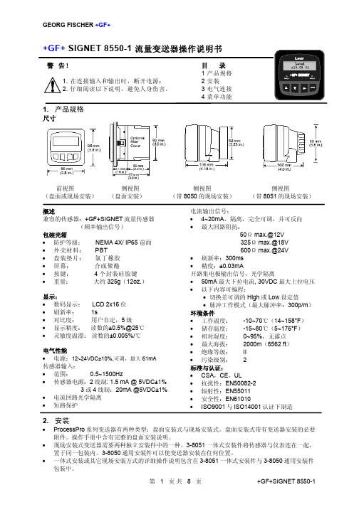
+GF+SIGNET 8550-1
*见辅助电源注意事项
辅助电源注意事项 只有当流量传感器需要的电流超过 1.5mA 时才 要用辅助电源。含有以下 SIGNET 流量传感器 时需要用辅助电源: • 2000 • 2507 • 2540(1999 年 1 月前产品) • 2530 • 2535 • 7002 涡街流量传感器
*见辅助电源注意事项
电气性能
• 电源:12~24VDC±10%,可调,最大 61mA
传感器输入:
• 范围:
0.5~1500Hz
• 传感器电源:2 线制: 1.5 mA @ 5VDC±1%
3 或 4 线制:20mA @5VDC±1%
• 电流回路光学隔离
• 短路保护
电流输出信号:
• 4~20mA,隔离,完全可调,并可反向 • 最大回路阻抗:
3.2 传感器输入连接 接线提示
• 不要将传感器的电缆与 AC 电缆敷设在同一根电缆导管内。电子噪音会干扰传感器信号。 • 将电缆敷设在接地的金属电缆管中有助于防止电子噪音与机械损伤。 • 将电缆入口处密封,以防潮汽的侵害。 • 每个端子只能插入一根导线。如果两根导线接入同一端子,要在外部连好。
对于 515/8510-XX,525,2517,以及任何输出正弦波信号的传 感器,最大电缆长度为 200ft(61m)。
• 工作温度: -10~70℃(14~158°F) • 储存温度: -15~80℃(5~176°F) • 相对湿度: 0~95%,无露点 • 最大海拔: 2000m(6562 ft) • 绝缘等级: II • 污染级别: 2 标准与认证:
GF Machining Solutions 系统3R 夹具 使用说明书

GF Machining SolutionsSystem 3R Toolingfor parts productionFitting the machines with the same reference system means that electrodes and workpieces can be moved between the machines without subsequent alignment and checking– One Minute Set-up.A reference system minimises setup timesEvery minute that can be converted from internal to externalsetting time increases the spindle time of the machine and withit the productivity of the business.Hourly invoicingSpindle time / week (hours)Revenue / week (€)Capital cost of machine (€)Faster payback,Conventional setting-up Pallet systemWorking time per day88Setting-up time per day (hours)-4-0.5Spindle time per day=4=7.5Working days per weekSpindle time per weekHigher productivitysized surfaces to ensure the6.35m m6.35 m mExample Micro Milling:WITHLess tool wearPowerTimeCutting forces -25%Tool life +30%.Conventional clampingVDPSpindle Speed (rpm)9 mm was the maximum allowed dept of cut for the cutting toolWithout VDPWith VDPA x i a l D e p t h o f C u t (m m )3R-600.1-303R-600.223R-600.203R-610.21-S3R-600.24-V3R-600.24-S3R-600.14-303R-600.1-30V3R-602.81DrawbarPallet/holderWorkpieceTable chuckindustry, you need to study every aspect of efficiency. It's spindle-hours from each machine, every day of the week. And here, the importance of a high-class reference system can never be over-estimated. A reference system which Macro is such a reference system. A system that minimises the throughput time, and which, thanks to its accuracy, Among users world wide, the Macro system is a byword for precision. And with good reason, since very single Macro But precision can be graded too. The Macro products are therefore “classified” in terms of accuracy, material and life – but always with full compatibility – as Standard, High Performance and Nano. Even so, it's worth remembering that the accuracy of a system is determined by the productRecommended tightening torque, manual chuck – 6 Nm✓3R-600.10-303R-651.7E-P & 3R-658.1E✓3R-651.7E-P& 3R-658.1E Weight 1.8 kg.3R-610.21-S✓3R-628.28-S3R-651.7E-XS3R-651.7E-P3R-651E-P 3R-651.70-P3R-601.7E-P3R-601.1E-P3R-651.70-XS3R-601.116-75PA3R-601.523R-651.75E-P 3R-628.28-S3R-A264883R-651.7E-XS3R-601.523R-A264883R-600.24-V✓✓Sealing ring, High, 3R-612.116-ASuitable for some Macro chucks with Sealing ring, Low, 3R-612.116-SSuitable for some Macro chucks with *For more info please ask System 3R.PT = Process Tooling3R-628.28-S 3R-A264883R-651.7E-XS3R-605.1E• Ø20x57.1 mm with flushing holes Ø7 mm• Supplied in sets of 10 pcs. 3R-605.1EE• Supplied in sets of 40 pcs.3R-605.2E• Ø20x36.9 mm with Ø7 mm flushing hole• Supplied in sets of 5 pcs. 3R-605.2EE• Supplied in sets of 20 pcs.DrawbarsOperating temp. +10 to +40° C3R-901-20Ewld hd vreferencing of workpieces and tools- a real challenge even with state of the art solutions available in the market. This becomes even more challenging when the references need precise and quick! The MacroNano clamping system links the production chain through an ultra-precision coupling DrawbarPallet/holderWorkpieceTable chuck3R-651.7E-N3R-651.75E-N3R-651E-N3R-601.1E-N3R-606-N3R-606.1-N3R-605.13R-600.10-3N3R-610.46-3N3R-600.84-3N3R-600.86-3N3R-601.1EMacroMagnum is larger variant of the patented Macrosystem. The high clamping force and the position of thereference surfaces far away from the chuck centre meanthat MacroMagnum can provide “Macro class” stability andaccuracy, even in applications with high machining forces.The double references of the chucks mean that in additionto the MacroMagnum pallets, the extensive range of MacroThe difference between a pallet and a referenceUsually the electrode blank is mounted directly on thepallet, which then carries the blank throughout themanufacturing process – from machine to machine,The reference elements are primarily intended to bemounted on the fixtures or vices in which the workpiecewill be clamped. The reference elements are significantlythinner in order to limit the total construction height.Required air pressure, pneumatic chuck – 6±1 barmanual chuck – MacroMagnum-pallet 10 Nm.DrawbarPallet/referenceelementWorkpieceTable chuck3R-680.19-23R-680.24-S 3R-680.1-23R-680.1-23R-680.24-S3R-680.24-V 3R-680.10-23R-680.24-S 3R-680.19-23R-680.1-2V 3R-680.10-33R-680.10-2A 90809.0390419.XX✓753R-682.600-A90356.20909643R-682.600-RS 3R-681.513R-680.19-2Drawbar3R-681.156-A904213R-681.513R-680.19-2✓Operating temp. +10 to +40° C38Ø6020Ø13535✓Measures to reduce the downtime of your machines matters is to keep the machines running. And that’s when you need an interface that gives fast setting-up.Setting-up in parallel away from the machine while it is working and then setting up in a matter of seconds properties of the Matrix system truly come into their drawbar with through hole. The through hole allows DrawbarPallet/holderChuckLowbuilt-in height.Spherical rolls .Pre-alignment studs.Inlets on side & underneath.Prepared for automatic Big through holeAllows high/long workpieces to be sunk into the chuck• Weight 2.7 kg.Ø1805020✓✓Drawbar, Matrix 142, 3R-695.2-142• Weight 7 kg.Three-jaw chuck mounted on a pallet.25 2Ø29852545.5Ø189p i c t u r m i s s imechanism.Releasing by airThe Z-references are airblast cleaned, throughnozzles in the Z-referncesHardened chuck body with prisms forX/Y centring made out of one piece formaximum stability. Indexing 4x90°.Sealing rings for completelysealed chuck-pallet interfaceagainst dirt and swarf.GPS 120 ring withreferences.GPS 70 ring withreferences.C 695 050 C 846 900 C 846 260C 188 300C 198 700C 188 730C 188 720✓✓C 695 140 C 695 050C 695 365 C 695 370 C 846 900C 695 270 C 846 260C 188 320C 188 770C 188 710C 530 310C 695 150C 190 120Pallet with coined cams Pallet with springy hardened cams✓✓Pallet with coined cams Pallet with springy hardened cams140100100160M8E FAD ✓Flange for GPS 120 chuck, C 190 125With airdock 4-fold. Fits on GPS 120 chuck C 190 120.Stainless steel, heat pre-treated Dimensions Ø160 x 20 mm Mounting 6x M8 onnections:A = releasing/clampingB = Air-blast cleaning of Z-referencesC = drain/pallet room ventingD = piston room venting E-G = medium connection.Pallet with coined camsWorkpiece Pallet/holderC 694 450 C 697 100C 694 650C 694 640 C 694 810C 694 610 C 846 600C 219 000 C 219 100 C 217 100C 219 200 C 219 800C 210 060The Z-references are air-blast cleaned, throughnozzels in the Z-references Clamping mechanism with spring clamping force by springs and clamping with balls aluminium pallets.Pallet with handles for manual pallet handling or automated pallet change by robot.✓✓WorkpiecePallet/holderTable chuck3R-770-190356.1090576.053R-770-590718.043R-770.6-13R-770.19-1D-20167D-2013090356.2290356.2190356.203R-771.23R-771.2-HCP3R-772.23R-CH771.35Delphin BIG3R-901-20EAutomation Catalogues+ WorkPal 1+ WorkPartner 1++ Fanuc, six-axis robot+ WSM – WorkShopManagerWorkPal 1– modest demands, major benefitsFor your own copy please contactWorking areaNo. of T slots _____________________________Make of machine _________________________Hardened/unhardened ________________________________________________Index3R-SSP059 (22)3R-SP15055 (15)3R-SP24460 (16)3R-SP26771 (16)3R-SP26771-RS (16)3R-SP26712 (34)3R-SP28219 (43)3R-SP28219-RS (43)3R-SP28268 (45)3R-SP28340 (47)3R-SP28340-RS (47)3R-SP28345 (49)3R-SP28395 (41)3R-SP29998 (46)3R-SP30752 (44)3R-SP30997 (44)3R-SP31380-RS (41)3R-SP7359 (16)3R-SP7359-RS (16)3R-SSP115-BASE ......22, 39, 77 3R-SSP115-Macro ..........22, 39 3R-SSP115-DYN.. (77)3R-TXXXX ........................24, 80 90027 . (24)90027.03 (38)90356.10 (73)90356.20 ..........................35, 75 90356.21 .. (75)90356.22 ..........................17, 75 90412.1X .. (16)90412.2X (16)90421 (38)90576.05 (73)90716.09 (13)90718.04 (73)90793 ...............................17, 35 90809.03 .. (34)90815 ..........................25, 39, 81 90842 . (12)90842.01 (23)90964 (35)C 188 300 (53)C 188 320 (56)C 188 710 (56)C 188 720 ...............................53C 188 730 . (53)C 188 770 (56)C 198 700 (53)C 190 120 (58)C 190 125 (58)C 210 060 (65)C 217 100 (65)C 219 000 (64)C 219 007 (70)C 219 100 (64)C 219 200 (64)C 219 650 (65)C 219 800 (64)C 522 520 (69)C 522 530 (69)C 522 540 (69)C 522 550 (69)C 522 800 (68)C 522 810 (68)C 522 820 (68)C 522 830 (68)C 522 850 (68)C 522 860 (68)C 522 870 (68)C 522 880 (68)C 530 210 (53)C 530 310 (56)C 531 000 (60)C 531 210 (70)C 531 250 (70)C 531 500 (70)C 694 100 (66)C 694 260 (67)C 694 270 (67)C 694 300 (66)C 694 400 (66)C 694 610 (66)C 694 640 (66)C 694 650 (67)C 694 810 (66)C 695 040 (54)C 695 050 (54)C 695 140 (57)C 695 150 (58)C 695 176 (60)C 695 265 (54)C 695 270 (54)C 695 295 (54)C 695 365 (57)C 695 370 (57)C 695 395 (57)C 697 100 (67)C 810 650 (71)C 810 710 (69)C 810 820 (69)C 810 830 (69)C 810 880-XX (71)C 810 960 (71)C 846 260 (59)C 846 360 (59)C 846 900 (59)C 846 600 (67)C 960 500 (60)C 960 740 .........................60, 71D-20130 (73)D-20167 (74)K-40338.1 (17)K-40338.2 (17)K-40338.3 (17)K-40338.4 (17)K-40338.5 (17)K-40339.1 (17)S 220 000 (70)S 220 400 (70)S 230 100 (59)S 230 150 (59)S 230 510 (59)S 500 090 (66)S 500 010 (54)S 500 011 (54)S 500 021 (57)S 500 100 (66)S 500 160 (66)S 500 170 (66)S 660 000 (59)GF Machining SolutionsT -2481-E (G F M S ) 18.10M a c h i n i n g S o l u t i o n s , S y s t e m 3R I n t e r n a t i o n a l A B , 2018 c t t o m o d i f i c a t i o n s .System 3R’s Customer Services is uniquely positioned to help you maximize the availability, value, precision and productivity of your System 3R equipment. Our cost-effective, customer-centric and expertservices put your success at the center, ramp up your productivity and ensure predictable, uninterrupted uptime. System 3R’s service engineers are yourexpert partners for a wide range of success-triggering services.For more info ask your local System 3R dealer.For contact details, please refer to: www.system3r .com.+ Ensuring productivity.+ Reducing running costs and wasted parts.+ Maximizing the return on your System 3R investments.+ Extending the product lifetime of your System 3R equipment while maintaining optimum precision.+ Ensuring robot cell safety satisfies present machine directives.Optimize the uptime of your equipment with our Customer ServicesC o m b i ,D e l p h i n , D y n a f i x , L o c x , L X , M a c r o , M a t r i x , O n e M i n u t e S e t -U p , O n e S y s t e m P a r t n e r , R 2R , S y s t e m 3R , V D P , W o r k M a s t e r , W o r k P a l , W o r k P a r t n e r , W o r k S h o p M a n a g e r , 3H P , 3R , 3R e a d y -T o -R u n a n d 3R e f i x a r e r e g i s t e r e d t r a d e m a r k s o f S y s t e m 3R .。
GFSignet产品技术参考手册说明书

Technical Reference Section: pH/ORPInformation in this section addresses frequently asked questions regarding pHCommon Acids1M HCl: 0.0 pHSulfuric Acid: 0.3 pHLemon Juice: 2.0 pHVinegar: 3.0 pHWine: 3.5 pHBeer: 4.5 pHMilk: 6.0 pHCommon BasesEgg Whites: 7.5 pHSeawater: 8.0 pHSodium Bicarbonate: 8.4 pHAmmonia: 11.6 pHPhoto Developer: 12.0 pH0.1M NaOH: 13.0 pHLye: 14.0 pHTechnical Reference Section: pH/ORPPrinciple of Operation• Standard pH/ORP electrodesare also commonly called combination electrodes; a pH/ORP measuring electrode and a reference measuring electrode are combined in a single body. The pH/ORP sensor measures the amount of hydrogen ions in the liquid. The pH signal is measured against the steady reference signal. Various chemical elements leaching through the porous reference junction can react with the reference electrolyte, dilute the electrolyte solution, or attack the silver chloride element; in either case, it will disturb the steady reference signal. Stray electrical currents will also affect the steady reference signal. A temperature element is also built into the pH/ORP combination electrode. Instruments interpret and temperature compensate the pH/ORP and reference signals into pH/ORP readings at 25°C (77°F). Signet offers three different groups of Standard pH/ORP Electrode Models: Models 2714-2717, 2754-2757, and 2774-2777• Differential pH/ORP electrodesfunction similar to the standard (combination) electrodes, but the reference design is modified and there is a third electrode, the solution ground. The pH and reference electrodes are measured against the solution ground. The solution ground drains stray currents away from the reference element, hence maintaining a steady signal at all times. The reference salt bridge slows or stops various chemical elements from leaching into the reference chamber . Chemicals that leach in may dilute the electrolyte but will not react with the glass-encased reference silver chloride element. The reference electrolyte can be refreshed if it is diluted or depleted. The temperature element is embedded in the pH/ORP electrode for an extremely quick response.Signet offers one group of DifferentialpH/ORP Electrodes: Models 2764 - 2767Cutaway of 2776 pH electrodeCutaway of 2766 pH electrodereference salt bridge3 (front chamber)temperature elementSignet offers what is called combination pH/ORP electrodes; a combination of three or four electrodes built into one common body that measures the pH or ORP of the solutions. These electrodes are the pH/ORP sensing element, temperature sensing element (pH only), the reference, and sometimes a solu-tion ground. An electrical path between the process solution, reference elec-trode, and the pH/ORP sensing electrode must always be present to complete the measuring circuit. When the circuit is broken or interrupted, the result is a faulty reading. There are only a few things in a chemical process that would high temperatures, and particles that can break the glass. On the other hand, there are many problems that can occur with the reference electrode. The reference silver chloride sensing element (wire) is exposed to the process liquid via the primary porous reference junction, which is in con-cals in the process. Many application liquids do not chemically react with the and therefore, a differential style electrode should be used. There are three advantages of the differential electrode:Standard versus Differential pH/ORP Electrodes:Technical Reference Section: pH/ORP A general rule of thumb is to use a differential electrode if you have mercury, copper, lead, chlorate, bromine, iodine, cyanide, or sulfide compounds in the differential electrodes.1. If the process chemicals attack the KCl electrolyte, the reference electrolyte chamber is refillable.2. If the reference junction becomes clogged by chemical reactions between the KCl and the process chemicals, the reference salt bridge is replaceable. 3. If there are stray currents or if there are process chemicals that attack the silver chloride wire in the standard electrodes, it will not attack it in the differential electrode because the wire is encased in a glass electrode.Technical Reference Section: pH/ORP• It is important that the sensing end of pH and ORP electrodes remain wet, for they may be permanently damaged if allowed to dehydrate. This is true for both in-line and submersible installation configurations. However, be careful to keep the electrical interconnection between electrode and preamplifier dry and clean at all times. Moisture in this area can also cause permanent damage.• pH control is best when performed in a tank. This is especially true in neutralization applications since it is very important for reagents to mix thoroughly with waste fluids, and to be allowed adequate time for the reactions to occur. Limiting adjustments to fewer than 3 pH units per stage, and sizing tanks to provide at least 10 minutes retention time, will increase the probability of producing safe effluents.• For bulb-style pH and ORP electrodes, significant natural self-cleaning by turbulent eddies is achieved at velocities of 1.5m/s or more (5 ft/s). Flat surface electrodes get adequate self-cleaning at velocities of 0.3 to 0.6m/s (1 to 2 ft/s). In all cases, exposure to velocities greater than 3m/s (10 ft/s) can cause excessive measurement noise and electrode wear and should be avoided.• The aging of pH and ORP electrodes (i.e., reference depletion and decreased glass sensitivity) results from a series of chemical reactions. And as a general rule, the rates of chemical reactions double with every increase of 10°C (50°F). This means shorter life expectancy for all pH and ORP electrodes as application temperatures increase.Important Application Tips• HF acid and strong caustics etch pH glass. High concentrations, especially at high temperatures, destroy electrodes quickly. For applications containing trace quantities of HF (<2%), use the Signet 3-2714-HF or 3-2754-HF electrode. This electrode has a polymeric constituent in the pH glass that resists attack by HF and extends the service life considerably over “normal” electrodes.• In applications where process temperatures will drop below 10°C (50°F), use the bulb-style electrodes in place of the Flat style electrode. This is a function of the electrical impedance of the glass that increases dramatically as temperature decreases. • Proper electrode placement within a tank is also very important. Electrodes should be mounted in well-mixed areas, away from reagent and waste introduction. It is usually advisable to position the electrode near the discharge outlet of the tank.• In-line pH control is not recommended because it is very difficult to determine the amounts of reagent necessary to achieve a desired reaction if both pH and flow are variables. However, in-line pH monitoring is very commonand useful.• Cleaning pH and ORP electrodes and calibrating the systems should be done regularly. The required frequency is application-dependent, but once/week for cleaning, and twice/month for calibration is recommended.• Isopropyl alcohol may be used for removing mild grease and oils from the pH sensitive glass or from the metallic tips of ORP electrodes. Use 5% HCl on porous reference junctions clogged with hard water deposits, or other solvents/detergents as necessary. Always consider the electrode’s materials of construction when selecting a cleanser . Technical Reference Section: pH/ORP ORP Values of Standard pH Buffers Saturated with Quinhydrone • The purpose of calibration is to compensate the system for the deplete and must be replaced. A good time to determine the condition of an electrode is after cleaning and during calibration. Note the mV readings in pH values: pH 7 = 0 mV, pH 4 = +177 mV, pH 10 = -177 mV. Replace output differs more than 50 mV table below: Maintenance Tips • 12 months at 25°C (77°F). • Refrigeration will extend this period, but do not allow them to freeze! Expansion of internal solutions during freezing can cause permanent damage to the electrodes. • The risk of putting older electrodes into service is the possible electrodes are marked with date codes to identify the date of manufacture.pH4pH7Temperature (°C)202530202530ORP Value (mV)268264258928779Technical Reference Section: Conductivity/Resistivity Conductivity is a measure of the abil-ity of a material to convey an electric current. The proper term for this ability of a solution is electrolytic conductivity, since only ions conduct electric current in solution. When dissolved in solution, many substanc-es such as salts, acids and bases dissociate into ions. Electrolytic conductivity (or simply conductivity) is therefore an indirect measure of the ionic concentration of a solution. Generally, conductivity increases and decreases with the concentration of ions.Unlike pH, which is a specific mea-sure of Hydrogen ion concentration, conductivity is a non-selective mea-surement of all the dissolved ionic species in a solution. As such, it is a highly utilized parameter in water, wastewater and industrial process analyses. For example, conductiv-ity is used to monitor the salt load of waters entering treatment facilities, to monitor and control the quality of drinking water and ultra-pure water, and to otherwise detect contaminants in industrial processes.According to the International Stan-dards Organization (ISO) the unit of conductance is the Siemens (S), after Werner von Siemens (1816-1892). However, the following three separate units of measure are commonly used to express conductivity: Siemens/cm (S/cm), mhos/cm, and μS/cm. Forany given measurement Siemens/cm and mhos/cm are exactly equal;1 µS 1 M Ω10 µS 100 K Ω1,000 µS 10,000 µS 50,000 µS 200,000 µS 100 µS 10 K Ω400,000 µS 100,000 µS 0.055 µS 18.2 M ΩCooling Tower Deionization Regen. Chemicals PPM TDS 5505005,00025,00050,000100,000200,000Information in this section addresses frequently asked questions regarding Conductivity (Resistivity) and is provided as REFERENCE ONLY to supplement procedures and recommendations specifically outlined in individual product instruction manuals. All manuals, data sheets, and additional helpful information are available at .they are merely different labels for the same value. The denominator in these units (cm) is sometimes trun-cated but is always assumed to be present. Ohm•cm is a unit of resistivity (the inverse of conductivity) and is fre-quently replaced by “Ω” the symbol for electrical resistance. Units of resistivity are most commonly associ-ated with ultra-pure water measure-ments in the millions of ohm•cm, or M Ω (megohms).Some users will also find it desir-able to express conductivity in terms of parts per million (PPM) or parts per billion (PPB) of total dissolved solids (TDS). Signet instruments accommodate this by allowing the entry of a TDS factor to convert from standard units of conductivity. (See the instruction manual of any current Signet conductivity instrument for details.)Conductivity is a measurement parameter with a very wide range. For example, ultra-pure water has a theoretical maximum resistivity of ap-proximately 18.2 M Ω, approximately 0.055 μS (microsiemens), whereas concentrated acids and bases can exceed 400,000 μS. Despite the wide-ranging possibilities most applica-tions for conductivity measurement are much narrower . Tap water, for instance, typically measures between 50 and 1,000 μS.Definition of Conductivity and Resistivity。
gegfi100出纳管理功能手册
目录第1章概述............................................................ -1 -1.1 简介 ........................................................ -1 -1.2 功能特点 .................................................... -1 -1.3 图标说明 .................................................... -1 - 第2章岀纳账管理........................................................ -3 -2.1 岀纳登账 .................................................... -32.2 现金盘点 ................................................... -4 -2.3 日结 ........................................................ -5 -2.4 月结 ........................................................ -52.5 岀纳日报表 ................................................. -52.6 岀纳账对账 (5)第3章支票管理........................................................ -7 -3.1 支票本 ...................................................... -73.2 支票处理 .................................................... -83.3 支票汇总表 (8)第4章银行对账........................................................ -9 -4.1 初始化 ...................................................... -9 -4.1.1 对账初始设置.................................... -9 -4.1.2 对账条件....................................... -10 -4.1.3 企业未达账..................................... -10 -4.1.4 银行未达账.................................... -11 -4.1.5 初始余额调节表................................ -11 -4.1.6 初始确认....................................... -12 -4.2 银行对账 .................................................... -124.2.1 对账单余额.................................... -12 -4.2.2 企业未达账.................................... -13 -4.2.3 银行未达账.................................... -13 -4.2.4 银行对账....................................... -13 -4.2.5 银行余额调节汇总表............................ -14 -4.2.6 银行余额调节明细表............................ -15 -第5章岀纟内报表..................................................... -16 -5.1 报表权限管理................................................. -165.2 报表查询..................................................... -175.3 资金看板 (18)第1章概述1.1简介岀纳管理子系统是新中大GE系统的核心系统之一,处理岀纳日常事务,如岀纳账管理、支票管理、银行对账等,是企业与外部银行间的桥梁。
GF冷热水管路系统技术手册

Georg Fischer Piping Systems
ఱඤሺഽ႙ᅚဗPE-RT ૐඤ࠶ୟဣཥ रຍ֩
概
缩写表
PB PE PP PEX PE-RT d EPDM e dCu DN Ø LK SW G R Rp M m SP g
与热水器相连时的注意事项: 根据美国《2000通用管道工程规范》(US“Uniform Plumbing Code 2000”)对塑 料管道的规定: 与热水器出口相连的管路系统,其最初至少500mm内不应直接使用塑料管。 因此,我们要求在PE-RT管与热水器之间应至少加装500mm的铜管、不锈钢管 或其他金属管材。
是已注册商标
1
塑料管材和管件的运输和储放
错误
正确
低温条件下,塑料管材受到冲击和挤压 后易受损。不同材料的温度极限如下表:
PE-RT PP-R PVC-C PB PE PEX -40°C +5°C -10°C -40°C -40°C
如果低于该温度,应对管材和管件进行保 护,以避免受冲击、挤压或其他外部机械 力而引起损伤。
೦้࣋क़)h*
X1
图1 DOWLEX 2388静液压强度参考曲线
图3 PE-RT II型静液压强度参考曲线
5
技术数据
系统应用
GF PE-RT管路系统应用于生活冷热水领域,能够满足 ISO使用条件 ISO 1级和 ISO 2级的要求。
使用 条件 1 2 4 设计温度 °C 60 70 20 40 60 20 60 80 时间Y. 49 49 2.5 20 25 14 25 10 最高工作温度 °C 80 80 70 时间Y. 1 1 2.5 故障温度 °C 95 95 100 时间h 100 100 100 典型 应用 60°C热水 70°C热水 地板采暖 散热器采暖 较高温度 散热器采暖
GF系列说明书
目录前言 (1)一、环境条件 (1)二、安全须知 (2)三、发动机 (4)1、发动机类型 (4)2、运转前检查 (4)3、发动机使用 (8)四、发电机 (17)1、结构简图 (17)2、技术参数 (19)3、电原理图 (21)4、发电机使用 (22)5、发电机维护 (22)五、搬运和储存 (23)六、常见故障 (24)1、发动机故障 (24)2、发电机故障 (25)10304JB/T 是根据前言GF 系列发电机-2001标准,研制开发出的一种新型发电设备。
该系列发电机采用稀土永磁体作为磁场源,无需传统的励磁绕组、发电机转子线圈、A VR 电压调制器,可靠性高,维护保养简单,操作简便。
其结构紧凑,体积小,重量轻,比传统发电机减轻30%左右。
一、环境条件发电机应在下列环境条件下才能正常使用。
1、周围环境空气温度范围在运行期间:-10°C~+40°C ;在运输和存储过程中:-25°C~+55°C 。
2、空气相对湿度40°C 时不超过50%;20°C 时不超过90%。
3、周围空气中的灰尘、酸、腐蚀性气体或物质不超过正常含量。
4、海拔高度不超过2000m 。
5、发电机的倾斜度不应超过15°。
二、安全须知您的生命及财产安全是十分重要的,本使用手册将指导您安全高效完成作业,安全操作规程将提醒您潜在的危险及其它伤害,每句警示语前均标有危险、注意等字样。
请留意本手册中标有“危险、警告、注意”三个警示词。
若不遵守操作规定您将有生命危险或严重伤害。
若不遵守操作规定您将有生命危险或严重伤害或您的机器损坏。
若不遵守规定您会受到伤害或您的机器及财产损坏。
每条安全标志告诉您是何种危险,将会发生什么及如何避免或减少伤害。
操作员须知✧在紧急情况下,如何迅速关掉发电机。
✧熟知所有发电机操控原理,电源的连接。
✧保证不使未受专业训练者操作;✧严禁儿童触碰机器。
一氧化碳✧废气含有大量毒素及一氧化碳,无色无味,大量吸入将导致昏迷或死亡。
GF SIGNET 2350 温度传感器操作说明书
目录
1. 产品概述 2. 产品规格 3. 安装 4. S3L™信号接线 5. 4~20mA 信号接线 6. 4~20mA 信号测量范围调整 7. 订货信息
2. 产品规格
兼容性
2.1 概述 接液部分材质: PVDF 温度量程: -10℃~100℃(14˚F~212˚F) 响应时间,τ: 10 s 过程连接形式:3/4 in. NPT 阳螺纹 后部连接形式:3/4 in. NPT 阳螺纹 电缆类型: 3 芯屏蔽电缆,22AWG
黑/红/白/屏蔽线
标准电缆长度: • 2350-1,-3: 4.6m(15ft.) • 2350-2: 16cm(6in.) 运输重量: 0.22kg(0.5lb) 电源要求: • S3L™输出信号:5VDC±10%,<1.5mA • 4~20mA 输出信号:12-24VDC±10% 有短路与电源极性反保护功能
编码 159 000 021 159 000 022 159 000 911
编码 159 000 753 159 000 188 159 000 755 159 000 839 159 000 841 159 000 761
产品描述
温度传感器,S3L™输出信号,3/4 in.NPT, 4.6m(15ft.)长电缆 温度传感器,S3L™输出信号,3/4 in.NPT, 16cm(6in.)长电缆 温度传感器,4~20mA 输出信号,3/4 in.NPT,4.6m(15ft.)长电缆
S3L™输出信号:串行 ASCII 码, TTL 9600bps • 精度: ±0.5℃( ±0.9˚F ) • 重复性: ±0.1℃( ±0.2˚F ) • 分辨率: 0.1℃(0.2˚F) • 刷新率: <100ms
INFICON-I O1000-I O-模块-快速安装指南说明书
Quick-start installation guide for I/O1000 I/O module Safety instructionsThis quick-start guide does not replace the installation manual for the I/O1000 I/O module. Safe use of the module is ensured only by reading the installation manual.Additional important information is provided in the installation manual for the I/O1000 I/O module. The manual can be found either on the USB memory stick or on the INFICON website. The USB memory stick is included with the shipment of the I/O module.Intended useThe I/O module is a device interface between the MSB box of the mass spectrometer module LDS3000 and an external controller, for example.►Install, operate and service the unit only in compliance with the installation manual.►Comply with the limits of application.User requirements►Operate and install the unit only if it is in perfect working order and as intended, in a safety-conscious manner and fully aware of dangers, in compliance with this manual.►Fulfill and ensure compliance with the following regulations:–Intended use–Generally applicable safety and accident prevention regulations–International, national and local standards and guidelines–Additional provisions and regulations that are specific to the unit►Use only original parts or parts approved by the manufacturer.►Keep the installation manual available at the operating site.►All work must be performed only by technical specialists who have been trained on the unit.►Allow personnel in training to work with the unit only under the supervision of technical specialists.►Make sure that the authorized personnel have read and understood this manual and all otherapplicable documents, especially the information on safety, maintenance and repairs, before starting work.►Define responsibilities, authorizations and supervision of personnel.User requirements►Read, observe and follow the information in the installation manual and the working instructionscreated by the owner, especially the safetyinstructions and warnings.►Perform all work based on the complete manual.Document: jima10en1-03 (1503)Mounting of I/O module✗DIN-TS35 top hat rail1Hook unit on top hat rail at bottom.2Press unit onto top hat rail at top.Connecting I/O module with leak detectorThe I/O module communicates via data cable with the leak detectorand is supplied with voltage by the data cable.✗Data cables from INFICON1Connect I/O module (connection LD) via data cable with leak detector.2Connect I/O module via desired interfaces with external controller:•RS232 (RS-232 interface)•RS485 (RS-485 interface)•A NALOG I N (analog input)•A NALOG O UT (analog outputs)•P LC I N (digital inputs)•P LC O UT (digital outputs)Description of the layoutsee Installation Manual for I/O module, jiqc10.FUSE and DIP switch S1, S2fFuses for digital outputs and DIP switches (under the cover)Fuses for digital outputs 1...4 and 5...8:2x0.75A (Schurter: 7010.9800.xx)1 = ON, 0 = OFF1 = ON, 0 = OFF, + = switching from OFF to ON during operation,X = randomFig: 1Mount I/O module on DIN-TS35 top hat rail Fig: 2Rear view of I/O module1PLC IN2RS2323STATUS4ANALOG OUT 5PLC OUT 6S1, S2 and FUSE 7LD8ANALOG IN9RS4851024V OUT DIP switch S1LDS3000HLD6000Contact4321 Factory setting (defaultvalue of the interfaceprotocol by the leakdetector or control unit)∙∙0000ASCII protocol∙∙0010 LD protocol∙∙0011 Binary protocol∙0101 LDS1000 protocol∙0110 Normal protocol∙0001 Simple protocol∙0100DIP switch S2Contact4321 Activate boot mode for software update X+00 Disable bus terminator 120Ω for RS-4851X00INFICON GmbH, Bonner Strasse 498, D-50968 Cologne, GermanyVisit our website for contact information and other sales offices worldwide. Document: jima10en1-03 (1503)。
gfconfig组态配置软件使用手册
gfconfig组态配置软件使用手册
1:在g5文件中运行gfconfig.exe程序。
新建IED文件——通讯系统建立三个节点。
——更改节点名称——点击下一节点名称保存——通道设定。
如图:
Cmd和是s104遥测量都为10。
点击左上角保存。
2:通信系统转发表设置。
3:工程文件导出
工程文件——晖保文件——右键(导出IDE配置文件)——文件名命名fy_sys.dc覆盖原有文件。
4:模拟数据。
运行程序。
——新建文档——address:01开始——
connection选择connect——modbus /TCP Svr——点击下列数据栏填写模拟数据.
(为固定数据——可选择三种数据模
式:Random为跳动数值。
Increment为依次替加数值。
Decrement依次替减数值)
5:查看数据转发报文
运行g5\bin\和如图所示:
点击选择本机。
如图:。
- 1、下载文档前请自行甄别文档内容的完整性,平台不提供额外的编辑、内容补充、找答案等附加服务。
- 2、"仅部分预览"的文档,不可在线预览部分如存在完整性等问题,可反馈申请退款(可完整预览的文档不适用该条件!)。
- 3、如文档侵犯您的权益,请联系客服反馈,我们会尽快为您处理(人工客服工作时间:9:00-18:30)。
创新软件公用平台使用帮助
一、概况
目前,院在精密楼主楼6-5房间集中安装部署了6套计算机辅助创新软件GFIN(GoldFire Innovator),安装部署情况如表一所示,其中的Innovator和Insight两种版本的功能差别请参考附件一。
为方便院科技人员就地使用计算机辅助创新软件GFIN,信息中心利用“远程终端服务”技术搭建了“创新软件公用平台”,所有在院“网络办公系统”的用户,均可在自己日常办公的计算机上利用“远程桌面连接”使用创新软件。
二、操作步骤
1,使用远程桌面连接
利用计算机系统自带的“远程桌面连接”,操作步骤为:“开始”->“所有程序”->”“附件”->“通讯”->“远程桌面连接”。
XP系统下的操作图例如下:
建议将该“远程桌面连接”建立为桌面快捷方式,步骤为:在刚才的“远程桌面连接”处,右键鼠标->“发送到”->“桌面快捷方式”。
图例如下:
点击后,则在桌面有一“远程桌面连接”图标,下次使用是直接双击该图标即可,结果如下:
2,设置远程连接参数
第一次使用时,通过“选项”设置需要连接的公用平台计算机的IP地址、用户名和密码、需映射的本机硬盘(以便将自己所作的工作和相关资料保存在自己的硬盘中)。
(1),点击“远程桌面连接”后,弹出“远程桌面连接”图框
(2),设置需要连接的计算机和用户名
点击“选项”后,在“常规”选项中输入需要连接的计算机IP地址和自己的用户名,
并将“允许我保存凭据”勾上,以便下次自动登录。
“计算机”栏输入IP地址,从172.18.25.101~172.18.25.106选一,请参照表一的安装部署情况表,选择自己需要连接的某台创新软件计算机的IP地址,目前每台创新软件计算机只允许最多5个用户同时连接,当不能连接时,请选择其它的IP。
“用户名”栏输入自己在院网络办公系统的用户名,初始密码为6个0,在登录到创新软件公用平台后,请利用“windows安全性”修改自己的密码。
(3)选择需要映射的本地资源,以便保存自己所做的工作到本地计算机的硬盘上
点击“详细信息”,弹出如图所示的“本地设备和资源”图框
的本地硬盘,以便保存自己所做的工作
(4),设置连接速度,点击“体验”,在“选择连接速度来优化性能”下拉框中,选择“局域网”,其它可以使用系统的默认选项。
3,登录到创新软件公用平台
点击“连接”,弹出登录用户名和密码输入框
请将“记住我的密码”勾上,以便下次自动登录,否则下次登录时,将提示输入登
录密码。
在系统弹出“是否信任此远程连接”的时候,将“请不要再询问我是否远程连接到此计算机”勾上。
登录成功后,将出现创新软件的工作桌面。
4,使用创新软件
点击桌面的“Goldfire”图标即可。
第一次使用时,需要输入创新软件的用户名和密码,请参照表一(GFIN安装部署情况表),根据你所连接的计算机IP地址,输入相应的创新软件的用户名和密码,并将“Remember password on this computer”勾上,以便下次自动登录创新软件。
5,修改登录密码
在登录到创新软件公用平台后,点击“开始”->“windows安全性”->“更改密码”,按提示框输入新旧密码即可。
6,断开连接
点击“开始”->“注销”即可。
注意:如果直接点击右上角图标×来关闭的话,该连接在较短时间内还将在服务器上保留,占用一个连接数(目前每台服务器连接数为5),需要等到服务器判断连接过期才会释放,建议采用注销来退出系统。
附件一:Innovator和Insight功能对照表。