模拟滤波器外文翻译
图像处理中值滤波器中英文对照外文翻译文献
中英文资料对照外文翻译一、英文原文A NEW CONTENT BASED MEDIAN FILTERABSTRACTIn this paper the hardware implementation of a contentbased median filter suitabl e for real-time impulse noise suppression is presented. The function of the proposed ci rcuitry is adaptive; it detects the existence of impulse noise in an image neighborhood and applies the median filter operator only when necessary. In this way, the blurring o f the imagein process is avoided and the integrity of edge and detail information is pre served. The proposed digital hardware structure is capable of processing gray-scale im ages of 8-bit resolution and is fully pipelined, whereas parallel processing is used to m inimize computational time. The architecturepresented was implemented in FPGA an d it can be used in industrial imaging applications, where fast processing is of the utm ost importance. The typical system clock frequency is 55 MHz.1. INTRODUCTIONTwo applications of great importance in the area of image processing are noise filtering and image enhancement [1].These tasks are an essential part of any image pro cessor,whether the final image is utilized for visual interpretation or for automatic an alysis. The aim of noise filtering is to eliminate noise and its effects on the original im age, while corrupting the image as little as possible. To this end, nonlinear techniques (like the median and, in general, order statistics filters) have been found to provide mo re satisfactory results in comparison to linear methods. Impulse noise exists in many p ractical applications and can be generated by various sources, including a number of man made phenomena, such as unprotected switches, industrial machines and car ign ition systems. Images are often corrupted by impulse noise due to a noisy sensor or ch annel transmission errors. The most common method used for impulse noise suppressi on n forgray-scale and color images is the median filter (MF) [2].The basic drawback o f the application of the MF is the blurringof the image in process. In the general case,t he filter is applied uniformly across an image, modifying pixels that arenot contamina ted by noise. In this way, the effective elimination of impulse noise is often at the exp ense of an overalldegradation of the image and blurred or distorted features[3].In this paper an intelligent hardware structure of a content based median filter (CBMF) suita ble for impulse noise suppression is presented. The function of the proposed circuit is to detect the existence of noise in the image window and apply the corresponding MFonly when necessary. The noise detection procedure is based on the content of the im age and computes the differences between the central pixel and thesurrounding pixels of a neighborhood. The main advantage of this adaptive approach is that image blurrin g is avoided and the integrity of edge and detail information are preserved[4,5]. The pro posed digital hardware structure is capable of processing gray-scale images of 8-bitres olution and performs both positive and negative impulse noise removal. The architectt ure chosen is based on a sequence of four basic functional pipelined stages, and parall el processing is used within each stage. A moving window of a 3×3 and 5×5-pixel im age neighborhood can be selected. However, the system can be easily expanded to acc ommodate windows of larger sizes. The proposed structure was implemented using fi eld programmable gate arrays (FPGA). The digital circuit was designed, compiled and successfully simulated using the MAX+PLUS II Programmable Logic Development S ystem by Altera Corporation. The EPF10K200SFC484-1 FPGA device of the FLEX1 0KE device family was utilized for the realization of the system. The typical clock fre quency is 55 MHz and the system can be used for real-time imaging applications whe re fast processing is required [6]. As an example,the time required to perform filtering of a gray-scale image of 260×244 pixels is approximately 10.6 msec.2. ADAPTIVE FILTERING PROCEDUREThe output of a median filter at a point x of an image f depends on the values of t he image points in the neighborhood of x. This neighborhood is determined by a wind ow W that is located at point x of f including n points x1, x2, …, xn of f, with n=2k+1. The proposed adaptive content based median filter can be utilized for impulse noisesu p pression in gray-scale images. A block diagram of the adaptive filtering procedure is depicted in Fig. 1. The noise detection procedure for both positive and negative noise is as follows:(i) We consider a neighborhood window W that is located at point x of the image f. Th e differences between the central pixel at point x and the pixel values of the n-1surr ounding points of the neighborhood (excluding thevalue of the central pixel) are co mputed.(ii) The sum of the absolute values of these differences is computed, denoted as fabs(x ). This value provides ameasure of closeness between the central pixel and its su rrounding pixels.(iii) The value fabs(x) is compared to fthreshold(x), which is anappropriately selected positive integer threshold value and can be modified. The central pixel is conside red to be noise when the value fabs(x) is greater than thethreshold value fthresho d(x).(iv) When the central pixel is considered to be noise it is substituted by the median val ue of the image neighborhood,denoted as fk+1, which is the normal operationof the median filter. In the opposite case, the value of the central pixel is not altered and the procedure is repeated for the next neighborhood window.From the noised etection scheme described, it should be mentioned that the noise detection level procedure can be controlled and a range of pixel values (and not only the fixedvalues of 0 and 255, salt and pepper noise) is considered asimpulse noise.In Fig. 2 the results of the application of the median filter and the CBMF in the gray-sca le image “Peppers” are depicted.More specifically, in Fig. 2(a) the original,uncor rupted image“Peppers” is depicted. In Fig. 2(b) the original imagedegraded by 5% both positive and negative impulse noise isillustrated. In Figs 2(c) and 2(d) the resultant images of the application of median filter and CBMF for a 3×3-pixel win dow are shown, respectively. Finally, the resultant images of the application of m edian filter and CBMF for a 5×5-pixelwindow are presented in Figs 2(e) and 2(f). It can be noticed that the application of the CBMF preserves much better edges a nddetails of the images, in comparison to the median filter.A number of different objective measures can be utilized forthe evaluation of these results. The most wi dely used measures are the Mean Square Error (MSE) and the Normalized Mean Square Error (NMSE) [1]. The results of the estimation of these measures for the two filters are depicted in Table I.For the estimation of these measures, the result ant images of the filters are compared to the original, uncorrupted image.From T able I it can be noticed that the MSE and NMSE estimatedfor the application of t he CBMF are considerably smaller than those estimated for the median filter, in all the cases.Table I. Similarity measures.3. HARDWARE ARCHITECTUREThe structure of the adaptive filter comprises four basic functional units, the mo ving window unit , the median computation unit , the arithmetic operations unit , and th e output selection unit . The input data of the system are the gray-scale values of the pi xels of the image neighborhood and the noise threshold value. For the computation of the filter output a3×3 or 5×5-pixel image neighborhood can be selected. Image input d ata is serially imported into the first stage. In this way,the total number of the inputpin s are 24 (21 inputs for the input data and 3 inputs for the clock and the control signalsr equired). The output data of the system are the resultant gray-scale values computed f or the operation selected (8pins).The moving window unit is the internal memory of the system,used for storing th e input values of the pixels and for realizing the moving window operation. The pixel values of the input image, denoted as “IMAGE_INPUT[7..0]”, areimported into this u nit in serial. For the representation of thethreshold value used for the detection of a no Filter Impulse noise 5% mse Nmse(×10-2) 3×3 5×5 3×3 5×5Median CBMF 57.554 35.287 130.496 84.788 0.317 0.194 0.718 0.467ise pixel 13 bits are required. For the moving window operation a 3×3 (5×5)-pixel sep entine type memory is used, consisting of 9 (25)registers. In this way,when the windoP1 P2 P3w is moved into the next image neighborhood only 3 or 5 pixel values stored in the memory are altered. The “en5×5” control signal is used for the selection of the size of th e image window, when“en5×5” is equal to “0” (“1”) a 3×3 (5×5)-pixel neighborhood is selected. It should be mentioned that the modules of the circuit used for the 3×3-pix el window are utilized for the 5×5-pixel window as well. For these modules, 2-to-1mu ltiplexers are utilized to select the appropriate pixel values,where necessary. The mod ules that are utilized only in the case of the 5×5-pixel neighborhood are enabled by th e“en5×5” control signal. The outputs of this unit are rows ofpixel values (3 or 5, respe ctively), which are the inputs to the median computation unit.The task of the median c omputation unit is to compute themedian value of the image neighborhood in order to substitutethe central pixel value, if necessary. For this purpose a25-input sorter is utili zeed. The structure of the sorter has been proposed by Batcher and is based on the use of CS blocks. ACS block is a max/min module; its first output is the maximumof the i nputs and its second output the minimum. The implementation of a CS block includes a comparator and two 2-to-1 multiplexers. The outputs values of the sorter, denoted a s “OUT_0[7..0]”…. “OUT_24[7..0]”, produce a “sorted list” of the 25 initial pixel val ues. A 2-to-1 multiplexer isused for the selection of the median value for a 3×3 or 5×5-pixel neighborhood.The function of the arithmetic operations unit is to computethe value fabs(x), whi ch is compared to the noise threshold value in the final stage of the adaptive filter.The in puts of this unit are the surrounding pixel values and the central pixelof the neighb orhood. For the implementation of the mathematical expression of fabs(x), the circuit of this unit contains a number of adder modules. Note that registers have been used to achieve a pipelined operation. An additional 2-to-1 multiplexer is utilized for the selec tion of the appropriate output value, depending on the “en5×5” control signal. From th e implementation point of view, the use of arithmetic blocks makes this stage hardwar e demanding.The output selection unit is used for the selection of the appropriateoutput value of the performed noise suppression operation. For this selection, the corresponding no ise threshold value calculated for the image neighborhood,“NOISE_THRES HOLD[1 2..0]”,is employed. This value is compared to fabs(x) and the result of the comparison Classifies the central pixel either as impulse noise or not. If thevalue fabs(x) is greater than the threshold value fthreshold(x) the central pixel is positive or negative impulse noise and has to be eliminated. For this reason, the output of the comparison is used as the selection signal of a 2-to-1 multiplexer whose inputs are the central pixel and the c orresponding median value for the image neighborhood. The output of the multiplexer is the output of this stage and the final output of the circuit of the adaptive filter.The st ructure of the CBMF, the computation procedure and the design of the four aforeme n tioned units are illustrated in Fig. 3.ImagewindoeFigure 1: Block diagram of the filtering methodFigure 2: Results of the application of the CBMF: (a) Original image, (b) noise corrupted image (c) Restored image by a 3x3 MF, (d) Restored image by a 3x3 CBMF, (e) Restored image by a 5x5 MF and (f) Restored image by a 5x5 CBMF.4. IMPLEMENTATION ISSUESThe proposed structure was implemented in FPGA,which offer an attractive com bination of low cost, high performance and apparent flexibility, using the software pa ckage+PLUS II of Altera Corporation. The FPGA used is the EPF10K200SFC484-1 d evice of the FLEX10KE device family,a device family suitable for designs that requir e high densities and high I/O count. The 99% of the logic cells(9965/9984 logic cells) of the device was utilized to implement the circuit . The typical operating clock frequ ency of the system is 55 MHz. As a comparison, the time required to perform filtering of a gray-scale image of 260×244 pixelsusing Matlab® software on a Pentium 4/2.4 G Hz computer system is approximately 7.2 sec, whereas the corresponding time using h ardware is approximately 10.6 msec.The modification of the system to accommodate windows oflarger sizes can be done in a straightforward way, requiring onlya small nu mber of changes. More specifically, in the first unit the size of the serpentine memory P4P5P6P7P8P9SubtractorarryMedianfilteradder comparatormuitiplexerf abc(x)valueand the corresponding number of multiplexers increase following a square law. In the second unit, the sorter module should be modified,and in the third unit the number of the adder devicesincreases following a square law. In the last unit no changes are requ ired.5. CONCLUSIONSThis paper presents a new hardware structure of a content based median filter, ca pable of performing adaptive impulse noise removal for gray-scale images. The noise detection procedure takes into account the differences between the central pixel and th e surrounding pixels of a neighborhood.The proposed digital circuit is capable ofproce ssing grayscale images of 8-bit resolution, with 3×3 or 5×5-pixel neighborhoods as op tions for the computation of the filter output. However, the design of the circuit is dire ctly expandableto accommodate larger size image windows. The adaptive filter was d eigned and implemented in FPGA. The typical clock frequency is 55 MHz and the sys tem is suitable forreal-time imaging applications.REFERENCES[1] W. K. Pratt, Digital Image Processing. New York: Wiley,1991.[2] G. R. Arce, N. C. Gallagher and T. Nodes, “Median filters:Theory and applicat ions,” in Advances in ComputerVision and Image Processing, Greenwich, CT: JAI, 1986.[3] T. A. Nodes and N. C. Gallagher, Jr., “The output distributionof median type filte rs,” IEEE Transactions onCommunications, vol. COM-32, pp. 532-541, May1984.[4] T. Sun and Y. Neuvo, “Detail-preserving median basedfilters in imageprocessing,” Pattern Recognition Letters,vol. 15, pp. 341-347, Apr. 1994.[5] E. Abreau, M. Lightstone, S. K. Mitra, and K. Arakawa,“A new efficient approachfor the removal of impulsenoise from highly corrupted images,” IEEE Transa ctionson Image Processing, vol. 5, pp. 1012-1025, June 1996.[6] E. R. Dougherty and P. Laplante, Introduction to Real-Time Imaging, Bellingham:SPIE/IEEE Press, 1995.二、英文翻译基于中值滤波的新的内容摘要在本设计中的提出了基于中值滤波的硬件实现用来抑制脉冲噪声的干扰。
中值滤波器脉冲噪声中英文对照外文翻译文献
中英文资料外文翻译文献Improved 2-D Median Filter for On-Line Impulse Noise Suppressiom Abstract-An inproved 2-D median filter employing multishell concept to suppress impulse noise ,is presented.The performance of proposed filter is evaluated over image ‘LENA’,The impulsive noise is added using MATLAB utility.The modified strategy reduces the mnuber of replacement and results in better performance and simple hardware realization that is suitable for on-line implementation.Index terms-Median Filter , Multi-shell Median Filter, Impulse NoiseI.INTRODUCTIONIn TV and other imaging systems,impulse noise is a common impairment . The standard T.V.Broadcast signal is often contaminated with impulsive noise arising from various sources such as household electrical appliance and atmospheric disturbances.Broad banding of the signal further increases the level of impulsive noise. V arious filters are proposed to suppress such impairments[1].The median filter(MF)[1-2] is widely usedfor impulse noise suppression and the multishell median filter(MMF)[3] introduces the concept of missing line recovery. Although these filters have satisfactory performance, MMF failsto filter two impulse noises in the same prossing window. Moveover,these filters tend to blur the images due to too many replacements. C.J.Juan proposed a modified multishell median filter (MMMF)[4], which removes most of the shortcomings associated with the MF and the MMF. However, it is observed that under certain condions, to be discussed in the follow sections, MMMF fails to perform the desired filtering operation .Moreover,the number of calculations/replacements invoved on the basis of MIN/MAX conditions is still too large and makes the filter difficult to realize,particulariy for real time applications.In this paper, the threshold strtegy of MMMF is modified so that:(a)effective noise filtering operations are performed under allconditions,and(b)number of calculations/replacements is reduced and simplified. This results in a simple hardware realization of the filter.II.PROPOSED MODIFICATIONConsider a 3x3-processing window, with P5 as the central pixel,as shown in Figure 1.P1 P2 P3P4 P5 P6P7 P8 P9Fig.1. A 3x3 processing windowThe output of MMMF as proposed in [4] isOutput (X,Y)= Max(P2,P8)if P5﹥Max[S]P5 if Min [s]﹤Max[S]Min(P2,P8) if P5﹤Max[S] (1)Where S is the set of samples surrounding central pixels except(P4.P6)i.e.S={P1,P2,P3,P7,P8,P9} (2) The principle invoved in the replacement strategy of Equation(1) is that if P5 is corrupted by noise ,it is better to replaceits gray level by P2 or P8 than by using Min[S] orMax[S] .also,due to missing lines error,since P4 and P6 may belost, they are not considered in Equation(2).The limitation of Equation(1) is that when Min[S] or Max[S] arealso corrupted by impulse noise,i.e.either Min[S] or Max[S] isequal to P5,Equation(1)fails to perform the desired filtering operation.To overcome this limitation following modificationsin the replacement strategy of Equation(1),are proposed.Output (X,Y)= Max(P2,P8)if P5≥Max[S]P5 if Min [s]<P5<Max[S] Min(P2,P8) if P5≤Max[S] (3)It has been observed that more than 70-80% points in an image,the gray level diatances of P5 from(P2 or P8) and from Max[S] are below 16.This is shown in Fig.2 for the image ‘LENA’.This fact is used to further reduce unnessary replacements,thereby reducing the bluring of the images.Thus taking into considertion of Figure(3) can be further modified asOutput (X,Y)= Max(P2,P8)if P5-Max[S]≥16Max(P2,P8) if Min [s]-P5≥16P5 otherwise (4)Equation 4 indicates that replacing action takes place only when the distance between P5 and Min[S] or Max[S] is no smaller than 16. This strtegy thus avoids the necessary replacements and reduces blurring of the images.Moreover,it can be implemented using simple comparators and subtractors.Gray level distancesFig.2. Gray level distances between central point and its neighboring points for the image ‘LENNA’Ⅲ .RESULTSFigure 3 shows the original image ‘LENNA’and Figure 4 shows the same image when corrupted with impulse noise. Results of median filter and the proposed filter are given in Figures 5 and 6, paring Figures 5 and 6, it is observed that the result of the proposed filter is much better than those obtained using the median filter. Aithough,the median filter remove the impulsive moise effectively, however,the image gets blurred.The proposed filter removes the impulsive noise and also preserves the details of the image.A multishell filter employing the modified replacement strategy is presentde in this paper.The modified filter effectively suppresses the inpulse moise.It uses threshold conditions that require fewer comparisons and replacements and is faster as compared to the other multishell median filters.moreover,it can be realized using simple comparators and subtractors and subtractors and hence can be effectively used in real time applications改进二维中值滤波器在线脉冲噪声的抑制摘要:一种改进二维中值滤波器,采用多壳的概念,以抑制脉冲噪声,拟定的过滤器的性能进行评估超过图像“LENNA”的中值滤波,脉冲噪声被添加使用到MATLAB的实用工具中。
电子信息工程专业外文翻译--滤波器

外文原文一、a question for study or discussion1.Research background and purpose1.1 conceptualizeElliptic filter (Elliptic filter), also known as the Call filter (Cauer filter), is in the passband and stopband ripple of a filter. Elliptic filter when compared to other types of filters, in order under the same conditions with minimal fluctuations in the passband and stopband. Same as its wave in passband and stopband, which distinguish it from the Butterworth filter with flat passband and stopband and flat passband and the stopband ripple or resistance with flat, cut than the snow filter passband ripple.A low-pass filter with a frequency response range of the ellipse:Four-order low-pass elliptic filter frequency response。
1.2 scientific researchIn the low-frequency (600Hz=500KHz) commonly used in band-pass filter, large LC filters, poor stability, stability of Crystal filters, but can only be made of narrow-band filter, bad shock and vibration resistance. Active filters are small, but stability and decay characteristics are often poor, and debugging easy. Ceramic filter is poor and low-frequency seismic performance of low temperature coefficient. And than snow filter Butterworth filter transfer function is a polynomial divided by a constant, for the whole network, all zeros in infinite, only infinite stopband attenuation is infinite, and the elliptic filter in both with zeros and poles on the limited frequency. Zero ripple in the passband, that it has a minimum across the passband and stopband ripple, This is distinguished from Butterworth filter with flat passband and stopband。
电子电路 数字模拟 外文翻译 外文文献 英文文献 电子电路 数字与模拟 下册
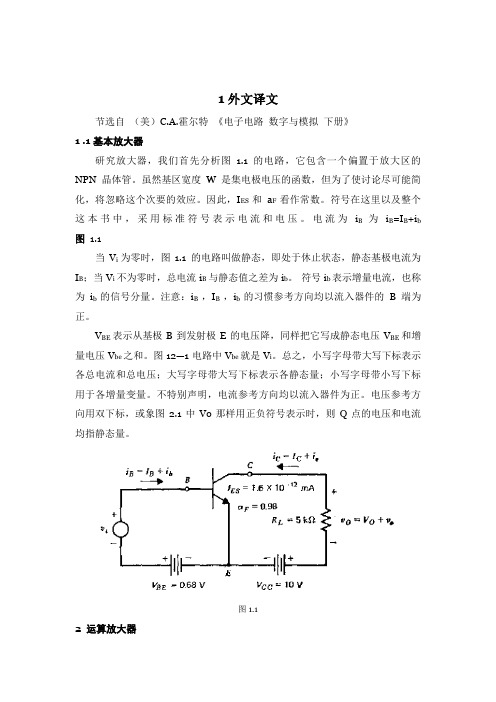
1外文译文节选自(美)C.A.霍尔特《电子电路数字与模拟下册》1 .1基本放大器研究放大器,我们首先分析图 1.1的电路,它包含一个偏置于放大区的NPN晶体管。
虽然基区宽度W是集电极电压的函数,但为了使讨论尽可能简化,将忽略这个次要的效应。
因此,I ES和a F看作常数。
符号在这里以及整个这本书中,采用标准符号表示电流和电压。
电流为i B 为i B=I B+i b 图 1.1当V i为零时,图1.1 的电路叫做静态,即处于休止状态,静态基极电流为I B;当V i不为零时,总电流i B与静态值之差为i b。
符号i b表示增量电流,也称为i b的信号分量。
注意:i B ,I B ,i b的习惯参考方向均以流入器件的B端为正。
V BE表示从基极B到发射极E的电压降,同样把它写成静态电压V BE和增量电压V be之和。
图12—1电路中V be就是V i。
总之,小写字母带大写下标表示各总电流和总电压;大写字母带大写下标表示各静态量;小写字母带小写下标用于各增量变量。
不特别声明,电流参考方向均以流入器件为正。
电压参考方向用双下标,或象图2.1中Vo那样用正负符号表示时,则Q点的电压和电流均指静态量。
图1.12 运算放大器除前一章讨论过的共射、共集和共基电路以外,还有另一种特别重要的基本组态,这就是差分放大器。
它有两个信号电压输入瑞和一个正比于输入信号差值的输出端。
常常,从提供负反馈的分压网络上提取输出的一部分作为一个输入电压;而有时,一个输入端甘脆接地。
在这两种情况下,差分放大器都变成只有一个输入和一个输出的单端放大器。
我们将看到,差分放大器可以处理较大的信号而没有过大的非线性失真,而且这个较大的动态范围是它的众多特性之一。
由于偏流不大时输入阻抗为中到高阻抗,所以信号源负载不会过重。
在低频工作(包括直流)是可能的。
其电路结构特别适合子集成电路制造,因而多数线性集成电路包含一级或多级差分放大器。
这类电路的实例有:模拟计算机网络、单片稳压器、视频放大器、模拟比较器和运算放大器。
第5章 模拟滤波器设计
第5章模拟滤波器设计滤波是信号处理的一种基本而重要的技术,利用滤波可从复杂的信号中提取所需要的信号,抑制不需要的部分。
第3章中利用FFT进行简单滤波的尝试已初步说明了这个问题。
所谓滤波器是指具有一定传输特性的信号处理装置。
本章首先介绍模拟滤波器设计原理,然后介绍几种常见原型滤波器的设计,尔后介绍将模拟原型滤波器转换为其他类型滤波器的频率转换方法,最后介绍MA TLAB中的模拟滤波器并通过应用实例进行说明。
5.1 滤波器的基本概念5.1.1滤波原理滤波器,顾名思义,其作用是对输入信号起到滤波的作用。
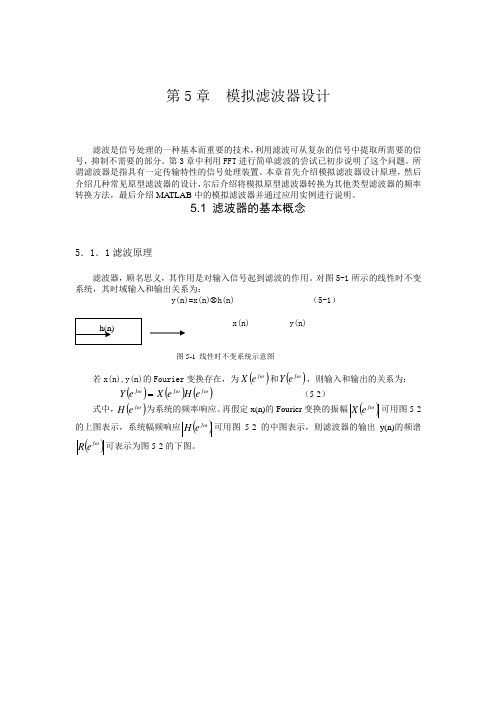
对图5-1所示的线性时不变系统,其时域输入和输出关系为:y(n)=x(n)⊗h(n) (5-1)x(n) y(n)图5-1 线性时不变系统示意图若x(n),y(n)的Fourier变换存在,为()ωj e X和()ωj e Y,则输入和输出的关系为:()()()ωωjωj ejY=(5-2)eHeX式中,()ωj e H为系统的频率响应。
再假定x(n)的Fourier变换的振幅()ωj e X可用图5-2的上图表示,系统幅频响应()ωj e H可用图5-2的中图表示,则滤波器的输出y(n)的频谱()ωj e R可表示为图5-2的下图。
图5-2 滤波器滤波示意图 这样,x(n)通过系统h(n)的结果是使输出y(n)中不再含有c ωω>的频率成分,而使c ωω<的成分“不失真”地给以通过。
因此设计出不同形状的()ωj e H 可以得到不同的滤波结果。
若滤波器的输入、输出都是离散时间信号,那么该滤波器的脉冲响应h(n)也必然是离散的。
我们称这样的滤波器为数字滤波器(digital filter )。
当用硬件实现一个数字滤波器时,所需的元件是延迟器、乘法器和加法器。
当在计算机上用软件实现时,它就是一段线性卷积的程序。
我们知道模拟滤波器只能用硬件来实现,其元件是电阻、电容、电感及运算放大器等。
5.1.2滤波器的分类滤波器的种类很多,分类方法也不同,如可以从功能上分,也可以从实现方法上分,或从设计方法上来分等。
外文翻译--数字滤波器的仿真与实现

毕业设计(论文)外文资料翻译院系电子信息工程专业电子信息工程学生姓名班级学号外文出处百度文库附件:1.外文资料翻译译文(约3000汉字);2.外文资料原文(与课题相关的1万印刷符号左右)。
英文原文The simulation and the realization of the digital filter With the information age and the advent of the digital world, digital signal processing has become one of today's most important disciplines and door technology. Digital signal processing in communications, voice, images, automatic control, radar, military, aerospace, medical and household appliances, and many other fields widely applied. In the digital signal processing applications, the digital filter is important and has been widely applied.1、figures Unit on :Analog and digital filtersIn signal processing, the function of a filter is to remove unwanted parts of the signal, such as random noise, or to extract useful parts of the signal, such as the components lying within a certain frequency range.The following block diagram illustrates the basic idea.There are two main kinds of filter, analog and digital. They are quite different in their physical makeup and in how they work. An analog filter uses analog electronic circuits made up from components such as resistors, capacitors and op amps to produce the required filtering effect. Such filter circuits are widely used in such applications as noise reduction, video signal enhancement, graphic equilibrium in hi-fi systems, and many other areas. There are well-established standard techniques for designing an analog filter circuit for a given requirement. At all stages, the signal being filtered is an electrical voltage or current which is the direct analogue of the physical quantity (e.g. a sound or video signal or transducer output) involved. A digital filter uses a digital processor to performnumerical calculations on sampled values of the signal. The processor may be a general-purpose computer such as a PC, or a specialized DSP (Digital Signal Processor) chip. The analog input signal must first be sampled and digitized using an ADC (analog to digital converter). The resulting binary numbers, representing successive sampled values of the input signal, are transferred to the processor, which carries out numerical calculations on them. These calculations typically involve multiplying the input values by constants and adding the products together. If necessary, the results of these calculations, which now represent sampled values of the filtered signal, are output through a DAC (digital to analog converter) to convert the signal back to analog form.Note that in a digital filter, the signal is represented by a sequence of numbers, rather than a voltage or current.The following diagram shows the basic setup of such a system.Unit refers to the input signals used to filter hardware or software. If the filter input, output signals are separated, they are bound to respond to the impact of the Unit is separated, such as digital filters filter definition. Digital filter function, which was to import sequences X transformation into export operations through a series Y.According to figures filter function 24-hour live response characteristics, digital filters can be divided into two, namely, unlimited long live long live the corresponding IIR filter and the limited response to FIR filters. IIR filters have theadvantage of the digital filter design can use simulation results, and simulation filter design of a large number of tables may facilitate simple. It is the shortcomings of the nonlinear phase; Linear phase if required, will use the entire network phase-correction. Image processing and transmission of data collection is required with linear phase filters identity. And FIR linear phase digital filter to achieve, but an arbitrary margin characteristics. Impact from the digital filter response of the units can be divided into two broad categories : the impact of the limited response (FIR) filters, and unlimited number of shocks to (IIR) digital filters.FIR filters can be strictly linear phase, but because the system FIR filter function extremity fixed at the original point, it can only use the higher number of bands to achieve their high selectivity for the same filter design indicators FIR filter called band than a few high-IIR 5-10 times, the cost is higher, Signal delay is also larger. But if the same linear phase, IIR filters must be network-wide calibration phase, the same section also increase the number of filters and net work complexity. FIR filters can be used the recursive method, not in a limited precision of a shock, and into the homes and quantitative factors of uncertainty arising from the impact of errors than IIR filter small number, and FIR filter can be used FFT algorithms, the computational speed. But unlike IIR filter can filter through the simulation results, there is no ready-made formula FIR filter must use computer-aided design software (such as MATLAB) to calculate. So, a broader application of FIR filters, and IIR filters are not very strict requirements on occasions.Unit from sub-functions can be divided into the following four categories :(1) Low-filter (LPF);(2) high-filter (HPF);(3) belt-filter (BPF);(4) to prevent filter (BSF).The following chart dotted line for the ideals of the filter frequency characteristics :2、MATLAB introducedMATLAB is a matrix laboratory (Matrix Laboratory) is intended. In addition to an excellent value calculation capability, it also provides professional symbols terms, word processing, visualization modeling, simulation and real-time control functions. MATLAB as the world's top mathematical software applications, with a strong engineering computing, algorithms research, engineering drawings, applications development, data analysis and dynamic simulation, and other functions, in aerospace, mechanical manufacturing and construction fields playing an increasingly important role. And the C language function rich, the use of flexibility, high-efficiency goals procedures. High language both advantages aswell as low level language features. Therefore, C language is the most widely used programming language. Although MATLAB is a complete, fully functional programming environment, but in some cases, data and procedures with the external environment of the world is very necessary and useful. Filter design using MATLAB, could be adjusted with the design requirements and filter characteristics of the parameters, visual simple, greatly reducing the workload for the filter design optimization.In the electricity system protection and secondary computer control, many signal processing and analysis are based on are certain types sinusoidal wave and the second harmonics of the system voltage and current signals (especially at D process), are mixed with a variety of complex components, the filter has been installed power system during the critical components. Current computer protection and the introduction of two digital signal processing software main filter. Digital filter design using traditional cumbersome formula, the need to change the parameters after recalculation, especially in high filters, filter design workload. Uses MATLAB signal processing boxes can achieve rapid and effective digital filter design and simulation.MATLAB is the basic unit of data matrix, with its directives expression mathematics, engineering, commonly used form is very similar, it is used to solve a problem than in MATLAB C, Fortran and other languages End precision much the same thing. The popular MATLAB 5.3/Simulink3.0 including hundreds of internal function with the main pack and 30 types of tool kits (Toolbox). kits can be divided into functional tool kits and disciplines toolkit. MATLAB tool kit used to expand the functional symbols terms, visualization modeling simulation, word processing and real-time control functions. professional disciplines toolkit is a stronger tool kits, tool kits control, signal processing tool kit, tool kits, etc. belonging to such communicationsMATLAB users to open widely welcomed. In addition to the internal function, all the packages MATLAB tool kits are readable document and the document could be amended, modified or users through original program the construction of new procedures to prepare themselves for kits.3、Digital filter designDigital filter design of the basic requirementsDigital filter design must go through three steps :(1) Identification of indicators : In the design of a filter, there must be some indicators. These indicators should be determined on the basis of the application. In many practical applications, digital filters are often used to achieve the frequency operation. Therefore, indicators in the form of general jurisdiction given frequency range and phase response. Margins key indicators given in two ways. The first is absolute indicators. It provides a function to respond to the demands of the general application of FIR filter design. The second indicator is the relative indicators. Its value in the form of answers to decibels. In engineering practice, the most popular of such indicators. For phase response indicators forms, usually in the hope that the system with a linear phase frequency bands human. Using linear phase filter design with the following response to the indicators strengths:①it only contains a few algorithms, no plural operations;②there is delay distortion, only a fixed amount of delay; ③the filter length N (number of bands for N-1), the volume calculation for N/2 magnitude.(2) Model approach : Once identified indicators can use a previous study of the basic principles and relationships, a filter model to be closer to the target system.(3) Achieved : the results of the above two filters, usually by differential equations, system function or pulse response to describe. According to this description of hardware or software used to achieve it.4、Introduction of DSPToday, DSP is widely used in the modern techno logy and it has been the key part of many products and played more and mo re important role in our daily life Recently, Northwestern Poly technical University Aviation Microelectronic Center has completed the design of digital signal processor co re NDSP25, which is aiming at TM S320C25 digital signal processor of Texas Instrument TM S320 series. By using top 2dow n design flow NDSP25 is compatible with instruction and interface timing of TM S320C25.Digital signal processors (DSP) is a fit for real-time digital signal processing for high-speed dedicated processors, the main variety used for real-time digital signal processing to achieve rapid algorithms. In today's digital age background, the DSP has become the communications, computer, and consumer electronics products, and other fields based device.Digital signal processors and digital signal processing is inseparably, we usually say "DSP" can also mean the digital signal processing (Digital Signal Processing), is that in this digital signal processors Lane. Digital signal processing is a cover many disciplines applied to many areas and disciplines, refers to the use of computers or specialized processing equipment, the signals in digital form for the collection, conversion, recovery, valuation, enhancement, compression, identification, processing, the signals are compliant form. Digital signal processors for digital signal processing devices, it is accompanied by a digital signal processing to produce. DSP development process is broadly divided into three phases : the 20th century to the 1970s theory that the 1980s and 1990s for the development of products. Before the emergence of the digital signal processing in the DSP can only rely on microprocessors (MPU) to complete. However, the advantage of lower high-speed real-time processing can not meet the requirements. Therefore, until the 1970s, a talent made based DSP theory and algorithms. With LSI technology development in 1982 was the first recipient of the world gave birth to the DSP chip. Years later, the second generation based on CMOS工艺DSP chips have emerged. The late 1980s, the advent of the third generation of DSP chips. DSP is the fastest-growing 1990s, there have been four successive five-generation and the generation DSP devices. After 20 years of development, the application of DSP products has been extended to people's learning, work and all aspects of life and gradually become electronics products determinants.中文翻译数字滤波器的仿真与实现随着信息时代和数字世界的到来,数字信号处理已成为当今一门极其重要的学科和技术领域。
滤波器的英文介绍
The basic principle of spread spectrum communicationSo-called spread spectrum communication, but simply indicates as follows: The "wide frequency communication is one intelligence transmission mode, its signal cabin holds the bandwidth far is bigger than passes on the information essentially the minimum bandwidth ; The frequency band expansion is completes through an independent code sequence, implements with the code and the modulation method, with passes on the information data to have nothing to do with; Uses the similar code in the receiving end to carry on the correlation synchronization receive, demodulation and recover passes on information data ".The wide frequency communication essential feature, is transmits the minimum bandwidth which the signal cabin takes (W) far to be bigger than (B) which primary information itself actual needs, its ratio is called the processing gain (Gp): In brief, we use the spread spectrum the wide band signal to transmit the information, is for enhance the communication the antijamming ability, namely under strong interferes the condition guaranteed the reliable security communicates. This is the spread spectrum communication basic thought and the theory basis.First, the main merit of wide frequency communications system* It’s easy to duplicate the frequency of use, raise the wireless frequency spectrum use factor* Strong anti-jamming, the error rate is low. Wide frequency communication when spatial transmission holds the bandwidth relative is wider, but the receiving end uses the correlation detection the means to solve expands, makes the useful wide band information signal to recover the narrow band signal, but non- needs the signal to expand the wide band signal, then extracts the useful signal through the narrow band filtering technology. This auspicious, regarding each kind of unwanted signal, because it in receives the end the non- relevance, after demodulation in the narrow band signal only has the very weak ingredient, the signal to noise ratio very high, therefore the anti-jamming is strong.* Good Privacy, is very small to each kind of narrow band communications system disturbance. Because the wide frequency signal expanded in the relative wider frequency band, in unit frequency band power very small, the signal is neglected in the noise, generally not easily was detected, but wants further to examine the signal the parameter (for example pseudo-random code sequence) difficultly, therefore said its privacy is good.* May implement a code minute site. The wide frequency communication enhanced the resistance to interference, the price takes the band width. But if many usersaltogether use this wideband, then may enhance the frequency band the use factor. Because has the wide frequency code sequence in the wide frequency communication the wide frequency modulation, fully uses between each kind of different code wide frequency code sequence the fine autocorrelation identity and the mutual correlation identity, carries on the solution in the receiving end using the correlation detection technology to expand, then in allocate may differentiate the different user for the different user code situation in the signal, extracts the useful signal. Like this many pair of users may simultaneously converse on the telephone in this frequency band but mutually does not disturb.* Anti- multi- diameters disturbance. In the wireless communication, since long ago, the multi- diameters disturbance throughout is one of questions which solves with difficulty. Uses the wide frequency code in the wide frequency communication the autocorrelation identity, extracts and separates the strongest useful signal in the receiving end from the multi- diameters signal, or the identical code sequence profile which comes many paths adds together the synthesis, all may the anti- multi- diameters disturbance function.Be different according to the spread spectrum mode, the existing wide frequency communications system may divide into following several kinds:* Direct sequence spread spectrum. The direct sequence spread spectrum (Direct Sequence Spread Spectrum) the work mode, is called straight expands (DSSS) the mode. The so-called direct sequence spread spectrum, is directly use the high rate wide frequency code sequence to expand the signal in the start the frequency spectrum. But in the receiving end, carries on the solution with the same wide frequency code sequence to expand, returns to original state the primitive information the stretch wide frequency signal.* Frequency-hopping (Frequency Hopping). Moreover one expansion signal frequency spectrum mode is called the frequency-hopping (FH - Frequency Hopping). The so-called frequency-hopping, compared with the accurate meaning is: Carries on the selection with the certain code sequence the multi- frequencies frequency-shift keying. In other words, carries on the frequency-shift keying modulation with the wide frequency code sequence, causes the carrier frequency unceasingly to jump, therefore is called the frequency-hopping.* Jumps when (Time Hopping). Is similar, jumps when (TH – Time Hopping) with the frequency-hopping is causes the transmitting message to jump in the time axis. First divides into the time axis many o'clock pieces. In does an in which time piece transmitting message carry on the check by the wide frequency code sequence. May jumps when the understanding be: Carries on selection with the certain code sequence many when pieces when moves the key modulation. Because used has very been narrow the very many time piece to transmit the signal, relatively mentioned, thesignal frequency spectrum also stretched.* Wide band linear frequency modulation (Chirp Modulation). The wide band linear frequency modulation work mode, is called the Chirp mode. If emanates radio frequency pulse signal in a cycle, its carrier spectrum frequency do change, then is called the linear frequency modulation.Second, direct sequence spread spectrum systemCompares with the general simulation or the digital communication system, the direct sequence spread spectrum in the information recognition and the demodulation, the radio frequency on frequency conversion and under the frequency conversion situation basic is same. Straight expands the communications system the main characteristic to lie in straight expands the signal the production, namely the wide frequency modulation and straight expands the signal the receive, namely the related solution expands.The wide frequency modulation is carries on the modulation with high rate PN code pulse sequence thus the expansion signal frequency spectrum. Usually uses the modulation mode is BPSK, the input signal and the PN code modulates in the balanced modulator outputs the stretch the wide frequency signal.Straight expands the system to carry on the modulation in the start with the PN code to expand the signal frequency spectrum. Is receiving the end generally to use the correlation detection or the matched filtering method solves expands. The so-called correlation detection, a simple metaphor is compares with the picture looks for the person. If wants to search the person in group of people which some is not acquainted with one another, the simplest valid method is in the hand has a Zhang person's picture, then with the picture one by one contrast, gets down like this, naturally can find some person. Same principle, when you want to examine the useful signal which needs, the valid method is in local produces a same signal, then with it with the signal contrast which receives, as desired similarity. In other words, is with the same signal which local produces with the signal which receives carries on the correlation operation, correlation function is biggest on the useful signal which most possibly is wants.The connected demodulation to be no doubt very good in the performance, but it needs to have the local PN code in the receiving end. This point sometimes brings many is not convenient. For example, the solution local signal and the receive signal synchronized question very is troublesome, but also cannot achieve real-time examines the useful signal. Because the matched filtering and the correlationdetection function in essentially is same, we may use the matched filter to demodulate t the straight -expand signal.The so-called matched filter, is a filter which matches with the signal, it can examines in the many kinds of signals or the disturbance with it match signal. This similarly is one kind of "looks for person" with the photograph the method. As for the video frequency rectangle pulse sequence that, the passive matched filter is on the tap delay line adds on the adder-accumulator.Third, frequency-hopping systemWe usually contact the wireless communications system all is the carrier frequency fixed communications system, like mobile phone and so on, therefore also is called as decides the frequency communication. This kind decides the frequency communications system, once will receive the disturbance on to cause the communication drop in quality, will be serious when will even cause the communication interrupt.Moreover in the enemy I in the duplex communication resistance, the enemy side attempt detects our communication frequency, in order to transmits to the interception the information content, or detected our telegraph is at position. Decides the frequency communications system to be easy to expose the goal also easy to intercept, by now, used the frequency-hopping communications quite to be covert with difficulty is also intercepted.Therefore, the frequency-hopping communications has the antijamming, the anti- interception ability, and can do frequency spectrum resource sharing. Therefore the frequency-hopping communications has displayed the huge superiority in the current modernized electronic warfare. Moreover, the frequency-hopping communications also applies in the civil communication by between the anti- decline, the anti- multi- diameters, the anti- network disturbs and raises the frequency spectrum use factor.In order to does not let the enemy side know we communicate the use frequency, needs frequently to change the carrier frequency, namely carries on the jump to the carrier frequency, in the frequency-hopping communications the carrier frequency change rule, is called the frequency-hopping design.The frequency-hopping signal receive, its process with decides the frequency to be similar. In order to after guarantee the mixing obtains the intermediate frequency signal, the requirement frequency synthesizer output frequency must outdo an intermediate frequency compared to the external signal. Because the external signal-carrier frequency is the jump, then requires the frequency which the local frequency synthesizer outputs also along with the external signal jump rule to jump, like this can obtain a fixed center quite signal through the mixing.The frequency-hopping is the frequency-hopping system key component, but frequency-hopping synchronization is the frequency-hopping system core technology. Frequency-hopping system synchronization including following several contents:* Receives the frequency-hopping design which the end and the start produces to be same, namely has the same frequency-hopping rule.* Receives, the start jump frequency should guarantee produces the fixed intermediate frequency signal in the receiving end, namely the jump carrier frequency with receives this locality which the end produces to jump the frequency to differ an intermediate frequency.* Frequency jump beginning and end time in time synchronization, namely synchronized jump, or phase coincidence.* When transmission numerical information, but also should achieve the frame synchronization and position synchronization.Fourth, PN codeThe PN code also calls the pseudo-random sequence. It has the approximate random sequence (noise) nature, but also can (cycle) produce according to the certain rule with the copying sequence. Because the random sequence is only can produce but cannot copy, therefore called it is the "pseudo" random sequence. The commonly used pseudo-random sequence has the m sequence, the M sequence and R –the S sequence.The msequencer from the belt feedback m level shift register framing,feeds back from certain levels after mold two Canada to the first level. It produces the sequence greatest length (cycle) is the 2n – 1 bit, altogether has 2m to plant the different state, one kind is entire "0" state. Only has when the feedback logic satisfies some kind of condition, the shift register outputs the sequence length is the 2n - 1 bit, achieves the greatest length. Otherwise produces the sequence could not achieve 2n - 1 bit of such is long. Therefore also is called the m sequence the greatest length linearity shift register sequence. Also is called the biggest shift register sequence.If in the feedback logic operation includes the multiplication operation or other logic operations, then is called as the nonlinear feedback logic. The sequencer frame which by the nonlinear feedback logic and the shift register can have the greatest length sequence, is called the greatest length non-linearity shift register sequence, or is called the M sequence, the M sequence greatest length is 2n.。
275个信号与系统常用词汇中英文对照表
275个信号与系统常用词汇中英文对照表序号英文词汇中文翻译1 Absolutely summable impulse response 绝对可和的冲激响应2 Absolutely integrable impulse response 绝对积的冲激响应3 Accumulation property 累加性质4 Adder 加法器5 Additivity 可加性6 Aliasing 混叠7 Allpass system 全通系统8 Amplitude Modulation(AM) 幅度调制9 Amplifier 放大器10 Analog-to-Digital Conversion 模数转换11 Analysis equation 分析方程12 Aperiodic signal 非周期性信号13 Associative property 结合性质14 Audio system 音频系统15 Autocorrelation function 自相关函数16 Band-limited signal 带限信号17 Band-limited interpolation 带限内插18 Bandpass filter 带通滤波器19 Bandpass-sampling technique 带通抽样方法20 Bandpass signal 带通信号21 Bandwidth of an LTI system 线性时不变系统的带宽22 Bilinear transformation 双线性变换23 Block diagram 方框图24 Bode plot 波特图25 Butterworth filter 巴特沃斯滤波器26 Carrier frequency 载波频率27 Carrier signal 载波信号28 Cartesian (rectangular) form for complex number 复数的笛卡尔(直角坐标)形式29 Cascade-form block diagram 级联型方框图30 Cascade (series) interconnection 级联连接31 Causal LTI system 因果的线性时不变系统32 Channel equalization 信道均衡33 """Chirp"" transform algorithm" 线性调频变换算法34 Closed-loop system 闭环系统35 Coefficient multiplier 系数乘法器36 Communication system 通信系统37 Commutative property 交换性质38 Complex conjugate 复共轭39 Complex exponential 复指数40 Complex number 复数41 Continuous-time signal 连续时间信号42 Conjugate symmetry 共轭对称性43 Conjugation property 共轭性质44 Continuous-time Fourier series 连续时间傅里叶级数45 Continuous-time Fourier transform 连续时间傅里叶变换46 Continuous-time system 连续时间系统47 Convolution integral 卷积积分48 Convolution sum 卷积和49 Correlation function 相关函数50 Cross-correlation function 互相关函数51 Cutoff frequency 截止频率52 Digital signal 数字信号53 Demodulation 解调54 Discrete-time 离散时间55 Discrete-time Fourier series 离散傅里叶级数56 Distributive property 分配性质57 Damped sinusoid 阻尼正弦波58 Damping ratio 阻尼比59 DC offset 直流偏置60 Decibel (dB) 分贝61 Delay 延迟62 Delay time 延时63 Difference 差分64 Discrete-time Fourier series 离散时间傅里叶级数65 Discrete-time Fourier transform 离散时间傅里叶变换66 Differential equation 微分方程67 Differentiation 微分68 Digital-to-Analog converter 数模转换器69 Direct FormⅠrealization 直接Ⅰ型实现70 Direct FormⅡrealization 直接Ⅱ型实现71 Dirichlet conditions 狄里赫利条件72 Discontinuity 不连续73 Discrete-time Modulation 离散时间调制74 Discrete-time signal 离散时间信号75 Decimation 抽取76 Discrete-time system 离散时间系统77 Distortion 失真78 Distributive property 分配性质79 Double-sideband modulation 双边带调制80 Downsampling 降率抽样81 Duality 对偶性82 Eigenfunction 特征函数83 Eigenvalue 特征值84 Elliptic filter 椭圆滤波器85 Energy-density spectrum 能量密度谱86 Envelope 包络线87 Equalization 均衡88 Euler's relation 欧拉关系89 Exponential 指数函数90 Fast Fourier Transform (FFT) 快速傅里叶变换91 Feedback 反馈92 Feedback interconnection 反馈互联93 Filter 滤波器94 Finite Impulse Response (FIR) 有限冲激响应95 Forward path 前向通路96 Frequency-selective 频率选择97 Frequency-shaping 频率整形98 Final-value theorem 终值定理99 Finite-duration signal 有限持续时间信号,100 First harmonic component 一次谐波分量101 First-order continuous-time system 一阶连续时间系统102 First-order discrete-time system 一阶离散时间系统103 Forced response 强迫响应104 Frequency-Division Multiplexing (FDM) 频分复用105 Frequency response 频率响应106 Frequency scaling 频率尺度变换107 Frequency shifting property 频移性质108 Fundamental frequency 基本频率109 Fundamental period 基本周期110 Gain 增益111 General complex exponential 普通的复指数函数112 Generalized function 广义函数113 Gibbs phenomenon 吉布斯现象114 Group delay 群延时115 Hanning window 汉宁窗116 Harmonic analyzer 谐波分析器117 Harmonic component 谐波分量118 Highpass filter 高通滤波器119 Hilbert transform 希尔伯特变换120 Ideal frequency-selective filter 理想频率选择滤波器121 Image processing 图像处理122 Imaginary part 虚部123 Impulse response 冲激响应124 Impulse train 冲激串125 Impulse-train sampling 冲激串抽样126 Incrementally linear system 增量线性系统127 Independent variable 独立变量,自变量128 Infinite Impulse Response (IIR) 无限冲激响应129 Initial-value theorem 初值定理130 Instantaneous frequency 瞬时频率131 Integral 积分132 Integration property 积分性质133 Integrator 积分器134 Interconnection 互联135 Linear Time Invariant (LTI) system 线性时不变系统136 Interpolation 内插137 Inverse Fourier transform 逆傅里叶变换138 Inverse Laplace transform 逆拉普拉斯变换139 Inverse system 逆系统140 Inverse z-transform 逆z变换141 Laplace transform 拉普拉斯变换142 Left-half plane 左半平面143 Left-sided signal 左边信号144 Linear constant-coefficient differential equation 线性常系数微分方程145 Linear constant-coefficient difference equation 线性常系数差分方程146 Finite Impulse Response (FIR) 有限冲激响应147 Linear feedback system 线性反馈系统148 Linear interpolation 线性内插149 Linearity 线性150 Lowpass filter 低通滤波器151 Lowpass-to-highpass transformation 低通到高通的转换152 Magnitude of complex number 复数的幅值153 Matched filter 匹配滤波器154 Memoryless system 无记忆系统155 Modulating signal 调制信号156 Modulation 调制157 Modulation index 调制指数158 Modulation property 调制性质159 Multiplexing 多路复用160 Multiplication 乘法161 Natural frequency 自然频率162 Natural response 自然响应163 Negative feedback 负反馈164 Network 网络165 Noncausal system 非因果系统166 Nonideal filter 非理想滤波器167 Nonrecursive filter 非递归滤波器168 Normalized function 归一化函数169 Nyquist frequency 奈奎斯特频率170 Nyquist rate 奈奎斯特速率171 Operational amplifier 运算放大器172 Orthogonal function 正交函数173 Orthogonal signal 正交信号174 Oversampling 过抽样175 Parallel interconnection 并联连接176 Parseval's relation 帕塞瓦尔关系177 Partial-fraction expansion 部分分式展开178 Passband frequency 通带频率179 Passband ripple 通带纹波180 Periodic complex exponential 周期性复指数181 Periodic convolution 周期卷积182 Periodic signal 周期信号183 Power 功率184 Periodic square wave 周期性方波185 Periodic train of impulses 周期性冲激串186 Phase lag 相位滞后187 Phase lead 相位超前188 Phase modulation 相位调制189 Phase shift 相移190 Polar form for complex number 复数的极坐标形式191 Pole 极点192 Pole-zero plot 零极点图193 Power of signal 信号的功率194 Power-series expansion method 幂级数展开法195 Principal-phase function 主值相位函数196 Proportional feedback system 比例反馈系统197 Real part 实部198 Rectangular pulse 矩形脉冲199 Rectangular window 矩形窗200 Recursive filter 递归滤波器201 Region of Convergence (ROC) 收敛域202 Rational function 有理函数203 Right-sided signal 右边信号204 Right-sided sequence 右边序列205 Right-half plane 右半平面206 Rise time 上升时间207 Root-locus analysis 根轨迹分析法208 Running sum 流动和209 Sampled-data feedback system 抽样数据反馈系统210 Sampling frequency 抽样频率211 Sampling function 抽样函数212 Sampling period 抽样周期213 Sampling theorem 抽样定理214 Scaling (homogeneity) property 比例(齐次)性215 Scaling in the z-domain Z域尺度变换216 Second harmonic component 二次谐波分量217 Second-order system 二阶连续时间系统218 Series (cascade) interconnection 串联(级联)连接219 Sifting property 移位性质220 shifting property in the s-domain s域移位性质221 Single-sideband sinusoidal amplitude modulation 单边带正弦幅度调制222 Singularity function 奇异函数223 Synchronous 同步的224 Sinusoidal frequency modulation 正弦频率调制225 Sinusoidal signal 正弦信号226 Sliding 滑动227 Square wave 方波228 Step-invariant transformation 阶跃响应不变变换法229 Step response 阶跃响应230 Stopband edge 阻带边缘231 Stopband frequency 阻带频率232 Stopband ripple 阻带纹波233 Sufficiency 充分性234 Summer 加法器235 Superposition property 叠加性质236 Symmetry 对称性237 Synthesis equation 综合方程238 System function 系统函数239 Stability 稳定性240 Taylor series 泰勒级数241 Time constant 时间常数242 Time delay 时延243 Time-Division Multiplexing (TDM) 时分复用244 Time-domain 时域的245 Time reversal property 时间翻转性质246 Time scaling 时间尺度变换247 Time shifting property 时移性质248 Time window 时间窗249 Transition band 过渡带250 Triangular window 三角窗251 Trigonometric series 三角级数252 Undamped natural frequency 无阻尼自然频率253 Undamped system 无阻尼系统254 Underdamped system 欠阻尼系统255 Unilateral Laplace transform 单边拉普拉斯变换256 Unilateral z transform 单边Z变换257 Unit circle 单位圆258 Unit delay 单位延时259 Unit doublet 单位冲激偶260 Unit impulse 单位冲激261 Unit impulse response 单位冲激响应262 Upsampling 升率抽样263 Variable 变量264 Vestigial sideband modulation 残留边带调制265 Voltage 电压266 Wideband 宽带267 Window function 窗函数268 Windowing 加窗269 Wireless 无线的270 Weighted average 加权平均271 Wavelength 波长272 Zero-input response 零输入响应273 Zero-state response 零状态响应274 Zero location 零点位置275 Zero-order hold 零阶保持器整理提供。
【精品】科技英语4低通滤波器原文和翻译
【关键字】精品Words and Expressionsintegrator n. 积分器amplitude n. 幅值slope n 斜率denominator n. 分母impedance n 阻抗inductor n. 电感capacitor n 电容cascade n. 串联passband n 通带ringing n. 振铃damping n. 阻尼,衰减conjugate adj. 共轭的stage v. 成为low-pass filters 低通滤波器building block 模块linear ramp 线性斜坡log/log coordinates 对数/对数坐标Bode plot 伯德图transfer function 传递函数complex-frequency variable 复变量complex frequency plane 复平面real component 实部frequency response 频率响应complex function 复变函数Laplace transform 拉普拉斯变换real part 实部imaginary part 虚部angular frequency 角频率frequency response 频率响应transient response 瞬态响应decaying-exponential response 衰减指数响应step function input 阶跃(函数)输入time constant 时间常数first-order filters 一阶滤波器second-order low-pass filters 二阶低通滤波器passive circuit 无源电路active circuit 有源电路characteristic frequency 特征频率quality factor n. 品质因子,品质因数circular path 圆弧路径complex conjugate pairs 共轭复数对switched-capacitor 开关电容negative-real half of the complex plane 复平面负半平面Unit 4 Low-pass FiltersFirst-Order FiltersAn integrator (Figure 2. la) is the simplest filter mathematically, and it forms the building block for most modern integrated filters. Consider what we know intuitively about an integrator. If you apply a DC signal at the input (i.e., zero frequency), the output will describe a linear ramp that grows in amplitude until limited by the power supplies. Ignoring that limitation, the response of an integrator at zero frequency is infinite, which means that it has a pole at zero frequency. (A pole exists at any frequency for which the transfer function's value becomes infinite.)(为什么为极点,为什么低通?)Figure A simple RC integratorWe also know that the integrator's gain diminishes with increasing frequency and that at high frequencies the output voltage becomes virtually zero. Gain is inversely proportional to frequency, so it has a slope of -1 when plotted on log/log coordinates (i.e., -20dB/decade on a Bode plot, Figure 2. 1b).Figure 2.1 b A Bode plot of a simple integratorYou can easily derive the transfer function asWhere s is the complex-frequency variable and is 1/RC. If we think of s as frequency, this formula confirms the intuitive feeling that gain is inversely proportional to frequency.The next most complex filter is the simple low-pass RC type (Figure 2. 2a). Its characteristic (transfer function) isWhen, the function reduces to , i.e., 1. When s tends to infinity, the function tends to zero, so this is a low-pass filter. When, the denominator is zero and the function's value is infinite, indicating a pole in the complex frequency plane. The magnitude of the transfer function is plotted against s in Figure 2. 2b, where the real component of s () is toward us and the positive imaginary part () is toward the right. The pole at - is evident. Amplitude is shown logarithmically to emphasize the function's form. For both the integrator and the RC low-pass filter, frequency response tends to zero at infinite frequency; that is, there is a zero at. This single zero surrounds the complex plane.But how does the complex function in s relate to the circuit's response to actual frequencies? When analyzing the response of a circuit to AC signals, we use the expression for impedance of an inductor and for that of a capacitor. When analyzing transient response using Laplace transforms, we use sL and 1/sC for the impedance of these elements. The similarity is apparent immediately. The in AC analysis is in fact the imaginary part of s, which, as mentioned earlier, is composed of a real part and an imaginary part.If we replace s by in any equation so far, we have the circuit's response to an angular frequency. In the complex plot in Figure 2.2b, and hence along the positive j axis. Thus, the function's value along this axis is the frequency response of the filter. We have sliced the function along the axis and emphasized the RC low-pass filter's frequency-response curve by adding a heavy line for function values along the positive j axis. The more familiar Bode plot (Figure 2.2c) looks different in form only because the frequency isexpressed logarithmically.(根据图翻译这两句话)Figure 2.2a A simple RC low-pass filterWhile the complex frequency's imaginary part () helps describe a response to AC signals, the real part() helps describe a circuit's transient response. Looking at Figure 2.2b, we can therefore say something about the RC low-pass filter's response as compared to that of the integrator. The low-pass filter's transient response is more stable, because its pole is in the negative-real half of the complex plane. That is, the low-pass filter makes a decaying-exponential response to a step-function input; the integrator makes an infinite response. For the low-pass filter, pole positions further down the axis mean a higher, a shorter time constant, and therefore a quicker transient response. Conversely, a pole closer to the j axis causes a longer transient response.So far, we have related the mathematical transfer functions of some simple circuits to their associated poles and zeroes in the complex-frequency plane . From these functions, we have derived the circuit ’s frequency response (and hence its Bode plot) and also its transient response. Because both the integrator and the RC filter have only one s in the denominator of their transfer functions, they each have only one pole. That is, they are first-order filters .Figure 2.2b The complex function of an RC low-pass filterFigure 2.2c A Bode plot of a low-pass filterHowever, as we can see from Figure 2.1b, the first-order filter does not provide a very selective frequency response. To tailor a filter more closely to our needs , we must move on to higher orders. From now on, we will describe the transfer function using f(s) rather than the cumbersome IN OUT V V . Second-Order Low-Pass FiltersA second-order filter has 2s in the denominator and two poles in the complex plane. You can obtain such a response by using inductance and capacitance in a passive circuit or by creating an active circuit of resistors, capacitors, and amplifiers. Consider the passive LC filter in Figure 2.3a, for instance. We can show that its transfer function has the formand if we defineLC /120=ωand R L Q /0ω=,then where 0ωis the filter's characteristic frequency and Q is the quality factor (lower R means higher Q).Figure 2.3a An RLC low-pass filterThe poles occur at s values for which the denominator becomes zero; that is,when 0/2002=++ωωQ s s . We can solve this equation by remembering that the roots of 02=++c bx ax are given byIn this case, a = 1, b 0ω=, and 20ω=c .The term (ac b 42-) equals ()4/1220-Q ω, so if Q isless than 0.5 then both roots are real and lie on the negative-real axis. The circuit's behavior is much like that of two first order RC filters in cascade . This case isn't very interesting, so we'll consider only the case where Q > 0.5, which means ()ac b 42-is negative and the roots are complex.Figure 2.3b A pole-zero diagram of an RLC low-pass filterThe real part is therefore a b 2/-, which is Q 2/0ω-, and common to both roots. The roots' imaginary parts will be equal and opposite in signs. Calculating the position of the roots in the complex plane, we find that they lie at a distance of0ωfrom the origin, as shown in Figure 2.3b. Varying 0ω, changes the poles' distance from the origin. Decreasing the Q moves the poles toward each other, whereas increasing the Q moves the poles in a semicircle away from each other and toward the ωj axis. When Q = 0.5, the poles meet at 0ω-on the negative-real axis. In this case, the corresponding circuit is equivalent to two cascaded first-order filters.Now let's examine the second-order function's frequency response and see how it varies with Q. As before, Figure 2.4a shows the function as a curved surface, depicted in the three-dimensional space formed by the complex plane and a vertical magnitude vector . Q =0.707, and you can see immediately that the response is a low-pass filter.The effect of increasing the Q is to move the poles in a circular path toward the ωj axis. Figure2.4b shows the case where Q = 2. Because the poles are closer to the ωj axis, they have a greater effect on the frequency response, causing a peak at the high end of the passband .Figure 2.4a The complex function of a second-order low-pass filter (Q = 0.707)Figure 2.4b The complex function of a second-order low-pass filter (Q = 2)There is also an effect on the filter's transient response. Because the poles' negative-real part is smaller, an input step function will cause ringing at the filter output. Lower values of Q result in less ringing, because the damping is greater. On the other hand, if Q becomes infinite, the poles reach the ωj axis, causing an infinite frequency response (instability and continuous oscillation) at 0ωω=. In the LCR circuit in Figure 2.3a, this condition would be impossible unless R=0. For filters that contain amplifiers, however, the condition is possible and must be considered in the design process.A second-order filter provides the variables 0ωand Q, which allow us to place poles wherever we want in the complex plane. These poles must, however, occur as complex conjugate pairs , in which the real parts are equal and the imaginary parts have opposite signs. This flexibility in pole placement is a powerful tool and one that makes the second-order stage a useful component in many switched-capacitor filters. As in the first-order case, the second-order low-pass transfer function tends to zero as frequency tends to infinity. The second-order function decreases twice as fast, however, because of the 2s factor in the denominator. The result is a double zero (零点) at infinity. 低通滤波器一阶滤波器从数学公式上讲,积分器(见图2.1a )是最简单的滤波器;它是构成大多数现代滤波器的基本模块。
本科毕设滤波器方面的中英文翻译
Abstract:A modification of the filter design described in Arcetri Technical Report N5/2002 is presented. The overall structure is similar, but the the digital local oscillator is moved after the rst lter and after the frequency decimation. With this modification the design proposed here presents some advantage in terms of gate usage and spectral dynamic range.1. IntroductionIn the hybrid correlator proposed for ALMA, a large fraction of the total logic and correlator cost is represented by the digital filter bank. Since the circuit is replicated in a large number of copies, even a modest reduction in complexity may have a relatively large impact on overall system cost. In report [8] a two stage tunable filter has been presented. The design, shown in fig. 2, is composed by a complex oscillator and mixer, a first decimating broad filter, a second sharp filter, and a complex to real conversion stage. The first filter has a road transition region, and thus a short FIR response time (128 taps).The second filter operates at the decimated frequency, allowing for a long response, and a sharp transition region, with only 64 taps. Both filters have complex samples and real coefficients.Figure 1: Structure of the original digital BBCThe signal is down converted by a digital LO/mixer, filtered by a first broad filter,re-quantized to 10 bit, filtered by a second sharp filter,converted to real representation, rescaled and re-quantized to a final resolution of 3 or 4 bits. Total power meters are used tomonitor signal level.A modified architecture (fig. 2), with almost identical performance and response, may be obtained moving the LO/mixer after the first filter. The first filter has a band pass corresponding to the desired portion of the input spectrum (without restrictions due to decimation), and is obtained from a the low pass prototype used in the previous approach, translated by a frequency equal to the LO setting.Figure 2: Structure of the modified digital BBCThe signal is first filtered by the broad filter, decimated, and then frequency converted by a full complex mixer. The second filter and output section is identical to the previous case. The filter is thus depending on the sub band position, and its coefficients must be reloaded every time the tuning change. To avoid aliasing, it must discriminate between positive and negative frequencies, It has therefore real input, complex (hermitian) tap coefficients, and complex output. The mixer/LO is fully complex, with 4 multipliers and 2 adders. The second filter and complex-to-real conversion stage is identical to the previous design.The main advantage of this design is that the mixer operates at the decimated frequency. Since a time multiplexed mixer is composed of 32 identical multipliers, even considering for the increased complexity in the multi-bit complex multiplier this results in a drastic simplification. It is possible to use a much better multiplier,thus increasing the global quantization efficiency (although by a small value, about 0.5%) and spurious free dynamic range.Another advantage is that the first filter operates on the 3-bit input data representation, instead of the 6-bit mixer output. This reduces the total filter size by a considerable amount (30-40%).A further advantage is that the mixer does not see any DC component that can beproduced by an offset in the sampler thresholds, as this is effectively filtered by the first filter. This DC component is equivalent to a strong monochromatic line, and may produce undesired spurs as it beats with the LO harmonics.2 Theory of operationFigure 3: Spectral processing exampleFor readability, a x8 multiplexing factor has been assumed, instead of x32. From top: (a) Input real signal, divided into 10 sub bands; (b) Undecimated and (c) decimated broad filter output; (d) Mixer output; (e) Sharp filter output.Signal processing for an hypothetical 1:8 decimated signal is shown in fig. 3 The real input, divided in 10 overlapped sub-bands, is shown in (a). The broad filter selects sub-band 6, with guard bands from sub-bands 5 and 7 (b). After decimation, (c) the band of interest occupies half the complex decimated bandwidth, with sub-bands 5 and 7 aliased in the remaining half. In the particular case, the band of interest folds from positive back to negative frequencies. After complex mixing the band of interest is centered on frequency zero (d), and the unwanted sub-bands are rejected by the sharp filter (e).The processing of a real simulated signal, with the desired 1:32 decimation factor, is shown in fig. 4 and 5.The signal is the same used in the previous report. The complex spectrum of the (real) input signal is shown in fig. 4a. The signal is composed of white noise, a strong out-of-band tone (-20dB), and a weaker (-30dB) in-band tone. The simulated signal is 2.5 ms long.After filtering, the signal is shown in fig. 4b. Only one side of the complex spectrum is preserved, thus avoiding undesired aliasing in the decimation operation.After decimation, the signal has the spectrum shown in fig. 4c. Even if the spectrum folds from positive to negative frequencies, no undesired alias of the strong input line can be seen.Figure 4: Spectral processing of a simulated signalFrom top: (a) Input real signal; (b) Undecimated and (c) decimated broad filter output Graphs have a logarithmic (dB) scale.The complex mixer rotates the filtered spectrum in order to present the desired passband to the sharp filter centered on frequency zero (fig. 5a). The low pass sharp filter then selects the desired passband and removes the undesired passbands (5b). This signal is then converted to real (5c), and re-quantized for correlation. The filter real output is exactly equal to that of the filter described in the previous report (apart from quantization effects).2.1 Broad band filterThe filter is a complex passband (real samples, complex coefficients) derived by the low pass prototype used in the previous design. The prototype has a bandpass equal to 1/64 the input bandwidth, and a guard region twice as large. After decimation, both the complexresponse and the two guard bands have a total width of 1/32 the initial band, or 1/2 the decimated complex band. The two guard bands fold in the same region of thedecimated band.The prototype is shifted by the desired center frequency. For 34 sub bands, the rotation for channel i(i =0,33) is (i-05)34*2 GHz, but arbitrary shift is possible. Thus, filter tuning is accomplished by calculation of a new set of coe?cients (no filter optimization is necessary) and reloading of the coe?cient memory.The real part of the filter is symmetric, while the complex one is antisymmetric. In both cases, filter structure may exploit this symmetry to reduce the number of multiplications. Filter conceptual schematic for the real (symmetric) branch is shown in fig 6. The demultiplexed inputs are fied to 32 identical groups of four taps each. Direct and inverse taps are summed together before multiplication. Folding and summing corresponding samples may present problems in a few-bit representation. The input samples are not actual values, but arbitrary codes. Summing the codes obviously does not work. The code is neither monotonic, nor equispaced. The signal must therefore be converted to a monotonic, equispaced code before the filter. This imposes a limitation on the possible quantization codes, resulting in a slightly reduction in quantization efficiency. A equispaced code (values 1, 3, 5, 7) has an quantization loss of 3.??%, against a loss.Figure 5: Spectral processing of a simulated signalFrom top: (a) mixer output; (b) Sharp filter output; (c)Real signal sent to the correlator.All plots are on a logarithmic vertical scale.The result of the sum of two codes (1, 3, 5, 7) can be any even number from -14 to 14, representable with a 4 bit, signed quantity. For 8 bit signed coe?cients, product size is 11 bit. Filter multipliers are therefore implemented with 16x11 bit RAM blocks.The filter has been designed using the filter from the previous design as a low-pass template, and multiplying each coefficient by the appropriate exponential.The same considerations about coefficient precision truncation apply for here. The actual filter shape,however, depends very much on the local oscillator setting. Truncation is an intrinsically nonlinear procedure, and only statistical properties of the filter shape can be anticipated. An alternative approach would be to use a nonlinear minimization program to adjust filter coefficients on the desired shape after filter rotation, instead of blindly truncate them. This approach would probably give a better stop band rejection (by 2-3 dB), at the expense of a much higher computational effort during filter reprogramming.2.2 Complex Local OscillatorThe local oscillator is greatly simpli?ed with respect to the previous approach. It is composed by a DDS.register, similar to the previous one, that generates a 10 bit phase value. No phase offset is needed, apart from the 90/180 degree phase switching. The 10 bit value is fed to asine/cosine lookup table, that produces a high resolution sine and cosine value. A complex multiplier, implemented with four hardwired multipliers and two adders, compute the expression y(t) = x(t)exp(2j t).The mixer does not select the bandwidth, it must only compensate for the unwanted rotation of the filtered band, and for its possible folding from positive to negative frequencies (as in the example shown in fig. 4). The complex mixing rotates the decimated band in order to have the frequency scale monotonically ordered from-625 MHz to +625 MHz. After conversion, the desired band is centered around frequency zero, and therefore.Figure 6: Coarse FIR schematicSignals from I and Q mixers are multiplied by coefficient taps in LUT tables. Input is from 32 time multiplexed streams, output is to 2 (I and Q) streams.can be filtered by alow-pass filter.The local oscillator value is programmed to the desired LO frequency modulus 125 MHz. The remaining part of the LO frequency affects only first filter coefficients, as bandwidth selection is done in this filter.The phase quantizationstep affects LO harmonicscontent. With 1024phase bins, the first harmonic appears Atharmonic number 1024,with an amplitude of approximately-60dB. Amplitude quantization in the sine/cosine table also generates harmonics, but with 8 bitsine/cosine representation the spur free dynamic range is around -70 dB.To reduce harmonic content, a small (few phase bins) pseudo-random noise can be added to the DDS phase.The resulting phase jitter is of the order of 1 degree, but is multiplied by the harmonic number, completely washing out the harmonics due to phase quantization.The lookup table can be simplified if only first quadrant values are stored, and the sign is treated separately. In this way, lookup table size is reduced to 1/4, and one more bit is available for the result.2.3 Sharp lter and output sectionThis section is identical to the design described in [8]Figure7: Complex localoscillator. A DDS register generatesa phasevalueSine andcosine values aregenerated in a lookup table. The complex multiplication is implemented in 4 hardwired multipliers and two adders.3 Considerations on FPGA resource usageImplementation of this filter require considerably less resources than the previous design. The broad filter has 3 bit input, instead of 6. This requires about half the resources in terms of configurable blocks, lookup tables. The saving in the adder chain is not so high, since most of the adder tree size is dictated by the coefficients size, not by the samples size. The lookup tables must be writable. This increases its complexity,especially in terms of routing resources. The mixer multiplier must be implemented using hard multipliers, not lookup tables. A single large look up table to hold sine/cosine values is still needed. Especially for Altera FPGAs, this is a large advantage, as these chips have smaller RAM blocks, but also one or two large RAMs.Re-tuning the band is relatively slower, the filter has no capability for frequency hopping. This is not a requirement, and tap reloading is in any case faster than for a full 1024 tap filter. Some intelligence is needed in the control processor to recalculate filter taps from thelow-pass prototype, but this is within the capabilities of any current microprocessor.摘要:它是一种Arcetri技术报告提出修改方案并设计的滤波器。
- 1、下载文档前请自行甄别文档内容的完整性,平台不提供额外的编辑、内容补充、找答案等附加服务。
- 2、"仅部分预览"的文档,不可在线预览部分如存在完整性等问题,可反馈申请退款(可完整预览的文档不适用该条件!)。
- 3、如文档侵犯您的权益,请联系客服反馈,我们会尽快为您处理(人工客服工作时间:9:00-18:30)。
(
(英文参考文献及译文)
二〇一〇年六月
本科毕业设计 题目:模拟滤波器软件包的设计
学生姓名:
学院:机械学院
系别:测控系
专业:测控技术
与仪器
班级
:测控08-2
指导教师:谭静高级实验师
基于MATLAB的模拟滤波器
1.1模拟滤波器简介
信号处理技术涉及到从不同类型的信号中提取信息来源的方法,同时也涉及到保护,存储并在稍后检索信息的方法。
例如,电讯系统,我们对兴趣从一个地方传输信息到另一个地方感兴趣,而在其他应用程序中,例如,MP3播放器,我们对在高效存储和信息检索感兴趣。
标记存储信息供以后检索,可以被看作是传输通过传输信道的信息伴随一个任意长的时间延迟。
在许多情况下,例如,MP3格式,信号处理已被用来删除nonaudible的技术(冗余)的信息,以减少需要存储的信息的量。
例如,在无线电系统,我们需要生成不同类型的信号,并修改信号,这样信息就可以在广播频道传输,例如,通过频率调制高频载波。
模拟滤波器是这些应用中的关键部件。
图 1.1说明了一个简单的数字传输系统模拟滤波器是关键部件。
计算机A 作为一个数字信号源生成一个ASCII符号序列。
“符号代表8位字。
以通过电话线传输一个符号,我们必须在符号位中指定一个物理信号适合传输信号。
在这里,我们使用一个具有两种不同频率的正弦电压作为载波信号和使用所谓的频移键控来代表信息。
在调制解调器A(调制器/解调器),我们让“零”位对应到980赫兹和“一”对应到1180赫兹。
因此,调制解调器B来确定,如果接收频率是980或1180赫兹,以确定是零还是一被传输。
两个能让正弦信号通过的带通滤波器,可以用于解决通过比较两个滤波器的输出振幅来接收到的信号频率。
以类似的方式,调制解调器B发送信息到调制解调器A,并且使用了1650和1850赫兹的频率。
因此,过滤是一个调制解调器的重要组成部分。
上面讨论的传输系统是现在过时了。
然而,现代传输系统具有更高的传输容量,使用类似的技术。
例如,高清晰度电视(HDTV),无线局域网(WLAN)和非对称数字用户线(ADSL),使用一些载体和更先进的调制方法。
然而,在这些系统中,不同类型的滤波器也是关键部件。
1.2信号和信号载体
常见信号和信号处理的例子如系统语音,音乐,图像,脑电图,心电图,地震信号和无线电,雷达,声纳,电视,电话和数字传输系统。
信号处理系统的特点是他们存储,传输,或信息的减少。
这个''信息''的概念有一个严格的科学定义,但在这里我们将从日常意义上解释“信息”的概念,例如,相当于在电话交谈表示什么。
此外,信息被解释为什么我们认为是利益,例如,说什么,但不是谁在讲话。
在不同的上下文中,有关资料可是说话者的身份。
1.2.1模拟信号
在信号处理系统信息表示为信号形式,而这往往是有连续时间和幅度的载波,在连续幅度和时间和不同“同样的方式作为信号“被称为模拟信号。
例如,来自麦克风的信号类似于不同的声压。
1.2.2连续时间信号
在这种情况下,信息和信号比照不同,即单对单,而是将信息嵌入信号以一种更复杂的方法。
例如,频率从调频发射机输出信号代表信息,即频率变化以和在信息里同样的方式(语音,音乐等)。
一般来说,一个信号,即在连续幅度和时间,但不会不同类似于与信息被称为连续时间信号。
因此,模拟信号属于连续时间信号一个子。
在这里,我们将只讨论模拟信号和系统,虽然是模拟滤波器讨论往往是有益的连续时间信号。
在这种情况下,它通常是足够的假设该信号可以被视为确定性,即,它们可以与描述函数x(T)。
然而,在许多情况下,它是要研究信号处理系统使用随机信号。
这样的信号,例如,代表电话线路上的噪声,包含随机变化,不能与普通的数学函数,统计方法必须使用代替。
1.2.3信号载体
一个信号是一个抽象的概念和关联一个载波。
对于持续时间或离散时间信号,这是在讨论下一节,载波始终是一个物理数量。
典型的信号运营商的电流,电压和电子电路充电,但也有机械振动和晶体中的应力是常见的。
压电材料电气和机械之间的转换数量。
在文献中,有被称为电路电压模式和电流模式的电路。
所不同的是首先使用负反馈,以减少组件错误,失真等效果,而后者只使用低量的反馈。
这意味着,电压模式电路不能可用于高频率电流模式电路,具有更高的灵敏度,而后者则在组件的错误和更大的信号失真。
术语信号和载波往往滥用。
它,然而,往往是重要的区分信号,其中包含从信号承载量中的信息。
1.2.4离散时间和数字信号
现代信号处理系统中经常使用的信号只定义在离散时间的实例。
这种离散时间信号往往是通过像连续时间信号的取样,离散时间信号是一个序列测量值或得的。
通常情况下,样本采取相同的时间距离,T,即,采样是统一的。
我们区分离散时间从这些连续值的信号量化。
一个信号,显示在图的左侧。
1.2只定义在离散的时间,并有连续值被称为离散时间信号。
如果信号也有量化值,说明右侧图。
1.2,信号被称为数字信号。
请注意,我们遗憾的是不加区分离散时间和数字信号之间在英国文学。
当然,信号不一定起源于连续时间信号的采样。
在事实上,它可能没有时间做。
例如,离散时间或数字信号可能通过抽样山的高度各个地方。
相应的信号是一个真正的函数的坐标,即一个两维信号。