
AOC 917Vw 液晶显示器电路图
AOC冠捷LM729液晶显示器电源电路的工作原理

AOC冠捷LM729液晶显示器电源电路的工作原理AOC冠捷LM729液晶显示器电源电路的工作原理液晶显示器的电源电路一般采用开关电路方式,此电源电路将交流220V输入电压经过整流滤波电路变成直流电压,再由开关管斩波和高频变压器降压,得到高频矩形波电压,最后经整流滤波后输出液晶显示器各个模块所需要的直流电压。
下面以AOCLM729液晶显示器为例讲解液晶显示器电源电路的工作原理。
AOCLM729液晶显示器的电源电路主要由交流滤波电路、桥式整流电路、软启动电路、主开关电路、整流滤波电路、过压保护电路等组成,其电源电路原理图如图b所示。
1.交流滤波电路交流滤波电路的作用是用于滤除由交流输入线引入的噪声,抑制电源内部产生的反馈噪声。
电源内部的噪声主要有共态噪声和正态噪声两种。
对于单相电源,输入侧有2根交流电源线和1根地线。
在电源输入侧2根交流电源线与地线之间产生的噪声为共态噪声;2根交流电源线之间产生的噪声为正态噪声。
交流滤波电路主要用于滤除这两类噪声,另外,还要起到电路过流保护和过压保护。
其中,保险用于过流保护,压敏电阻用于输入电压过压保护。
如图5-3所示为交流滤波电路原理图。
图中,电感L901、L902,电容C904、C903、C902、C901组成了EMI滤波器。
电感L901、L902用于滤除低频共态噪声;C901和C902用于滤除低频正态噪声;C903和C904用于滤除高频共态和正态噪声(高频电磁干扰);限流电阻R901、R902用于拔下电源插头时对电容起放电作用;保险F901用于过流保护压敏电阻NR901用于输入电压过压保护。
当液晶显示器的电源插头插入电源插座后,220V交流电经过保险管F901、压敏电阻NR901防浪涌冲击后,通过由电容C901、C902、C903、C904,电阻R901、R902,电感L901、L902组成的抗干扰电路后进入桥式整流电路。
2.桥式整流滤波电路桥式整流滤波电路的作用是将220V交流电经过全波整流后转变为直流电压,再经过滤波后将电压变为市电电压的2倍。
AOC 915SW+液晶显示器维修资料OB2269CP
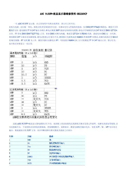
AOC915SW+液晶显示器维修资料OB2269CP一台AOC915SW显示器,在正常使用中突然出现黑屏,指示灯已经不亮。
此机为电源、高压板一体化,拆机后检查发现保险丝完好,目测未见有元件烧焦的痕迹,仅C802(50V470uf)轻微鼓包。
测量开关管K3115完好,通电测量5V和24V输出为0伏,断电后测量300V滤波电容泄放电缓慢,放电后仔细测量发现24V整流管D801(LT7224)击穿,5V供电D805/D8077(LT7732)正常,拆卸D801时断为两截,整流管LT7224用FD302代换,滤波电容C802也一并代换,继续测量24V后级未见短路现象,通电试机指示灯依旧不亮,测量贴片电源集成块SG6841的8脚0V未摆动,此脚为场效应管K3115的G控制脚,0V说明IC为工作,测量3脚启动脚电压0V,用块新的SG6841换上后开机测量5V和24V输出正常,指示灯亮,按开机后屏幕显示一切正常。
冠捷AOC915SW+液晶显示器电源指示灯不亮.按面板上的各按钮均无效拆机目测未发现元件虚焊、电解电容鼓包等现象。
以为是接触不良,于是把机内各排线重新插拔,把按键板断开,故障依旧。
测量电源板各输出电压,发现3.3V、Sv、16V电压均无输出,整流滤波后的318V正常,初步判断故障在桥式整流及滤波之后部分。
OB2269CP引脚功能测量电源控制芯片OB2269CP的3脚启动电压,当表笔碰到GND引脚时,灯管突然亮了,观察显示器已经正常工作了。
装好后试机也正常,但郁闷的是,闲置两三天之后再开机,故障依旧!因无AOC915SW+的电路图纸,故根据印刷电路板绘制电路简图,如下图所示。
IC芯片引脚电压会受外围元器件的影响,比如外围有开路、短路、漏电或变质等都会使引脚电压发生变化,偏离正常值。
应重点检查OB2269的(3)、(7)、(8)脚的电压,但是,当用万用表量这些引脚电压时,原先无法点亮的显示器就可以正常工作了。
宏基X173W液晶彩色显示器技术资料及电路图

1Acer X173WService Guideh tt p://ww w .wj e l.n e tService Guide Version and Revision2Copyright © 2003 by Acer Incorporated. All rights reserved. No part of this publication may be reproduced, Transmitted, transcribed, stored in a retrieval system, or translated into any language or computer language, inany form or by any means, electronic, mechanical, magnetic, optical, chemical, manual or otherwise, withoutthe prior written permission of Acer Incorporated.DisclaimerThe information in this guide is subject to change without notice. Acer Incorporated makes no representations or warranties, either expressed or implied, with respect to the contents hereof and specifically disclaims any warranties of merchantability or fitness for any particular purpose. Any Acer Incorporated software described in this manual is sold or licensed "as is". Should the programs prove defective following their purchase, the buyer (and not Acer34Before using this information and the product it supports, please read the following general information. 1. This Service Guide provides you with all technical information relating to the BASIC CONFIGURATION decided for Acer's "global" product offering. To better fit local market requirements and enhance product competitiveness, your regional office may have decided to extend the functionality of a machine (e.g. add-on card, modem, or extra memory capability). These LOCALIZED FEATURES will NOT be covered in this generic service guide. In such cases, please contact your regional offices or the responsible personnel/channel to provide you with further technical details.2. Please note WHEN ORDERING FRU PARTS, that you should check the most up-to-date information available on your regional web or channel. If, for whatever reason, a part number change is made, it will not be noted in the printed Service Guide. For ACER-AUTHORIZED SERVICE PROVIDERS, your Acer office may have aDIFFERENT part number code to those given in the FRU list of this printed Service Guide. You MUST use the listprovided by your regional Acer office to order FRU parts for repair and service of customer machines.Warning: (For FCC Certified Models)Note: This equipment has been tested and found to comply with the limits for a Class B digital device, pursuant toPart 15 of the FCC Rules. These limits are designed to provide reasonable protection against harmful interference in a residential installation. This equipment generates, uses and can radiate radio frequency energy, and if not installed and used in accordance with the instructions, may cause harmful interference to radio communications. However,there is no guarantee that interference will not occur in a particular installation. If this equipment does cause harmful interference to radio or television reception, which can be determined by turning the equipment off and on, the user is encouraged to try to correct the interference by one or more of the following measures: 1. Reorient or relocate the receiving antenna.2. Increase the separation between the equipment and receiver.3. Connect the equipment into an outlet on a circuit different from that to which the receiver is connected.4. Consult the dealer or an experienced radio/TV technician for help. Notice:1. The changes or modifications not expressly approved by the party responsible for compliance could void the user's authority to operate the equipment.2. Shielded interface cables and AC power cord, if any, must be used in order to comply with the emission limits.3. The manufacturer is not responsible for any radio or TV interference caused by unauthorized modification to this equipment. It is the responsibility of the user to correct such interference.As ENERGY STAR ® Partner our company has determined that this product meets the ENERGY STAR ® guidelines for energy efficiency.Warning:To prevent fire or shock hazard, do not expose the monitor to rain or moisture. Dangerous high voltages are present inside the monitor. Do not open the cabinet. Refer servicing to qualified personnel only.h tt p://ww w.wj e l.n e t5Precautionsz Do not use the monitor near water, e.g. near a bathtub, washbowl, kitchen sink, laundry tub, swimming pool or ina wet basement.z Do not place the monitor on an unstable trolley, stand, or table. If the monitor falls, it can injure a person and cause serious damage to the appliance. Use only a trolley or stand recommended by the manufacturer or sold with the monitor. If you mount the monitor on a wall or shelf, uses a mounting kit approved by the manufacturer and follow the kit instructions.z Slots and openings in the back and bottom of the cabinet are provided for ventilation. To ensure reliable operation of the monitor and to protect it from overheating, be sure these openings are not blocked or covered. Do not place the monitor on a bed, sofa, rug, or similar surface. Do not place the monitor near or over a radiator or heat register. Do not place the monitor in a bookcase or cabinet unless proper ventilation is provided. z The monitor should be operated only from the type of power source indicated on the label. If you are not sure of the type of power supplied to your home, consult your dealer or local power company.z The monitor is equipped with a three-pronged grounded plug, a plug with a third (grounding) pin. This plug will fit only into a grounded power outlet as a safety feature. If your outlet does not accommodate the three-wire plug, have an electrician install the correct outlet, or use an adapter to ground the appliance safely. Do not defeat the safety purpose of the grounded plug.z Unplug the unit during a lightning storm or when it will not be used for long periods of time. This will protect themonitor from damage due to power surges.z Do not overload power strips and extension cords. Overloading can result in fire or electric shock.z Never push any object into the slot on the monitor cabinet. It could short circuit parts causing a fire or electric shock. Never spill liquids on the monitor.z Do not attempt to service the monitor yourself; opening or removing covers can expose you to dangerous voltages and other hazards. Please refer all servicing to qualified service personnelz To ensure satisfactory operation, use the monitor only with UL listed computers which have appropriate configured receptacles marked between 100 - 240V AC, Min. 5A.z The wall socket shall be installed near the equipment and shall be easily accessible.Special Notes On LCD MonitorsThe following symptoms are normal with LCD monitor and do not indicate a problem.Notesz Due to the nature of the fluorescent light, the screen may flicker during initial use. Turn off the Power Switch and then turn it on again to make sure the flicker disappears.z You may find slightly uneven brightness on the screen depending on the desktop pattern you use.z The LCD screen has effective pixels of 99.99% or more. It may include blemishes of 0.01% or less such as a missing pixel or a pixel lit all of the time.z Due to the nature of the LCD screen, an afterimage of the previous screen may remain after switching the image, when the same image is displayed for hours. In this case, the screen is recovered slowly by changing the image or turning off the Power Switch for hours.h tt p://ww w.wj e l.n e t6Table Of ContentsChapter 1Monitor Features ………………………………………… 7 Introduction……………………………………… 7 Electrical Requirements……………………………………… 8 LCD Monitor General Specification ……………………………………… 9 LCD Panel Specification ……………………………………… 10 Support Timing ……………………………………… 12 Monitor Block Diagram ……………………………………… 13 Main Board Diagram ……………………………………… 14 Software Flow chart ……………………………………… 15 Main Board Layout ……………………………………… 17 Installation……………………………………… 18 Attaching/Removing the base ……………………………………… 19Chapter 2Operating Instructions ………………………………………20 External Controls ………………………………………20 Front Panel Controls ……………………………………… 21 eColor Management (OSD) ……………………………………… 22 How to Adjust a Setting ………………………………………23 LOGO………………………………………28Chapter 3Machine Disassembly………………………………………29Chapter 4 Troubleshooting……………………………………… 34Chapter 5Connector Information………………………………………38Chapter 6FRU (Field Replacement Unit) List ……………………………………… 39 Exploded Diagram……………………………………… 40Chapter 7Schematic Diagram………………………………………43h tt p://ww w.wj e l.n e tChapter 1 Monitor FeaturesIntroductionScopeThis specification defines the requirements for the 17” MICROPROCESSOR based Multi-mode supported high resolution color LCD monitor. This monitor can be directly connected to general 15-pin D-sub VGA connector, also supports VESA DPMS power management and plug & play function. There is a build-in stereo audio amplifier with OSD control to drive a pair of speakers.DescriptionThe LCD monitor is designed with the latest LCD technology to provide a performance oriented product with7Electrical RequirementsStandard Test ConditionsAll tests shall be performed under the following conditions, unless otherwise specified.nits = cd/(m2) = Ft-L x 3.426lux = foot-candle x 10.768LCD Monitor General Specification910LCD Panel SpecificationGeneral SpecificationsMechanical Informationh tt p://ww w.wj e l.n e tOptical Specificationsh tt p://ww w.wj e l.n e tSupport Timingh tt p://ww w.wj e l.n e tThe LCD MONITOR will contain a main board, a power board, and keypad board which house the flat panel control logic, brightness control logic and DDC.The power board will provide AC to DC Inverter voltage to drive the backlight of panel and the main board chips each voltage.Software Flow ChartRemark:Main Board LayoutInstallationh tt p://ww w.wj e l.n e tAttaching/Removing the Baseh tt p://ww w.wj e l.n e tOperating InstructionsPress the power button to turn the monitor on or off. The other control buttons are located at front panel of the monitor. By changing these settings, the picture can be adjusted to your personal preferences. • The power cord should be connected.• Connect the video cable from the monitor to the video card.• Press the power button to turn on the monitor position. The power indicator will light up.External ControlsItem Description Item DescriptionChapter 2h tt p://ww wFront Panel Controlh tt p://ww w.wj e l.n e teColor Management (OSD)h tt p://ww w.wj e l.n e tHow to Adjust a Settingh tt p://ww w.wj e l.n e tAdjusting the pictureh tt p://ww w.wj e l.n e th t t p ://w w w .w j e l .n e th tt p://ww w.wj e l.n e tOSD Messagea. Outlineb. The Description For OSD MessageLogoWhen the monitor is power on, the LOGO will be showed in the center, and disappear slowly.How To Optimize The DOS-Mode Plug And PlayPlug & Play DDC2B FeatureThis monitor is equipped with VESA DDC2B capabilities according to the VESA DDC STANDARD. It allows the monitor to inform the host system of its identity and, depending on the level of DDC used, communicate additional information about its display capabilities.The DDC2B is a bi-directional data channel based on the I²C protocol. The host can request EDID information overthe DDC2B channel.This monitor will appear to be non-functional if there is no video input signal. In order for this monitor tooperate properly, there must be a video input signal.This monitor meets the Green monitor standards as set by the Video Electronics Standards Association (VESA) and/or the United States Environmental Protection Agency (EPA) and The Swedish Confederation Employees (NUTEK). This feature is designed to conserve electrical energy by reducing power consumption when there is no video-input signal present. When there is no video input signals this monitor, following a time-out period, will automatically switch to an OFF mode. This reduces the monitor's internal power supply consumption. After the video input signal is restored, full power is restored and the display is automatically redrawn. The appearance is similar toa "Screen Saver" feature except the display is completely off. Pressing a key on the keyboard, or clicking the mouse restores the display. Using The Right Power CordThe accessory power cord for the Northern American region is the wallet plug with NEMA 5-15 style and is UL listed and CSA labeled. The voltage rating for the power cord shall be 125 volts AC.Supplied with units intended for connection to power outlet of personal computer: Please use a cord set consisting of a minimum No. 18 AWG, type SJT or SVT three conductors flexible cord. One end terminates with a grounding type attachment plug, rated 10A, 250V, and CEE-22 male configuration. The other end terminates with a molded-on type connector body, rated 10A, 250V, having standard CEE-22 female configuration.Please note that power supply cord needs to use VDE 0602, 0625, 0821 approval power cord in European counties.h tt p://ww w.wj e l.n e tMachine DisassemblyThis chapter contains step-by-step procedures on how to disassemble the monitor formaintenance.Disassembly Procedure1. Remove the cover hinge marked in red. (Fig 1)Fig 12. Remove the screws to release base stand . (Fig 2)Fig 2 Chapter 3h tt p://ww w.wj e l.n e t3. Remove the back cover and regard the hook. (Fig 3-4)Fig 3Fig 44. Remove the bezel. (Fig 6)Fig 5h tt p://ww w.wj e l.n e t5. Remove the keyboard. (Fig 6)6. Remove the screws to remove the panel. (Fig 7-10)http://Fig 7 Fig 8 31www. wjel.netFig 6Fig 97.Remove the screw as following indicate to remove the main board and power board. (Fig 11-13)http://Fig 11 32www. wjFig 10el.netht tp :// wwFig 12 Fig 1333w. wj el. ne tTroubleshootingThis chapter provides troubleshooting information for the X173W:1. No PowerChapter 4No powerPress power key and look if the picture is normal NG Please reinsert and make sure the AC of 100-240 is normalOKMeasure U201 Pin 2=3.3VNG OKwwOK 34Check if X401 oscillatehttpReplace X401://NG Replace U401 if the picture is normal NG Replace U501waveforms are normalw. wjOKMeasure CN201 Pin3=5V?el.power section Replace U201NGReinsert or check thenet2. No PictureNo pictureMeasure U201 PIN2=3.3VOKNGReplace U201Check if X401oscillate waveforms are normalOKNGCheck if the sync signal from computer is output and video cable is connected normallywwNG 35OKReplace U401, U501http://w. wjInput the sync signal of computer, or change the cableel.Replace X401net3. Panel Power CircuitCheck CN601 PIN 1,2,3 should have response from 0V to 5V When we switch the power switch from on to off NGCheck the PPWR panel power relative circuit Q601, Q602 In normal operation, when LED =green, R601 low level, If PPWR no-response when the power switch Turn on and turn off, replace the U401- RTD2120LOKReplace panel4. Keypad BoardIs Keypad board connecting normally?OKww36Is Button Switch normally? OKtp://NG Is Keypad board normally?htOKCheck main boardw. wjNG NGOSD is unstable or not workingel.Connect Keypad Board Replace Button Switch Replace Keypad Boardnet5. No BacklightCheck C802 (+) =12V NGOKChange FB801Check ON/OFF signal NGOKCheck Interface boardNG OKCheck the pin9&10 of IC801 have PWM wave NGOKwwNG NM 37Check the resonant wave of pin6 & pin1 for T801 OKtp://Check Q802 Change T801htCheck the output of T801OKCheck connecter & lampw. wjOK Replace IC801Change Q801/Q804/Q811/Q812el.Change Q805.Q808 or Q810neCheck IC801 pin12=12V?tConnector InformationThe following figure shows the connector locations on the monitor:Chapter 5http://38www. wjel.netFRU (Field Replaceable Unit) Listchapter whenever ordering for parts to repair or for RMA (Return Merchandise Authorization).Chapter 6This chapter gives you the FRU (Field Replaceable Unit) listing in global configurations of X173W.Refer to thisNOTE: Please note WHEN ORDERING FRU PARTS, that you should check the most up-to-date information available on your regional web or channel (/spl/). For whatever reasons a part number change is made, it will not be noted in the printed Service Guide. For ACER AUTHORIZED SERVICE PROVIDERS, your Acer office may have a DIFFERENT part number code from those given in the FRU list of this printed Service Guide. You MUST use the local FRU list provided by your regional Acer office to order FRU parts for repair and service of customer machines. NOTE: To scrap or to return the defective parts, you should follow the local government ordinance or regulations onhttp://39www. wjel.nethow to dispose it properly, or follow the rules set by your regional Acer office on how to return it.Exploded Diagram (Model: X173W)http://40www. wjel.net41Part ListAbove picture show the description of the following component.h tt p://ww w.w j e llejw4243Schematic DiagramMain BoardCN201Chapter 74445T77SRDDNHSABN 1X173B 46Monday , July 09, 2007715G2498-1-K-AC 04.MCU/RTD2120L G2498-1-K-AC-1-070707OEM MODEL Size Rev DateSheetofTPV MODEL PCB NAME 称爹T P V ( Top Victory Electronics Co . , Ltd. )Key Component絬 隔 瓜 絪 腹46U T{4}4}I{4}47PPWR_ON#{4}T77SRDDNHSABN 1X173A 66Monday , July 09, 2007715G2498-1-K-AC 06.OUTPUTG2498-1-K-AC-1-070707OEM MODEL Size Rev DateSheetofTPV MODEL PCB NAME 称爹T P V ( Top Victory Electronics Co . , Ltd. )Key Component絬 隔 瓜 絪 腹LVDS Panel ( FFC Type ){5}CN601{5}Power board48CN80149。
创维 26S19IW 线路图 和AOC L26BH83线路图 版号:715G3418P020HV003M

8
电视设定 以下菜单只有在电视模式才出现:
1. 自动搜台: 用于给用户自动搜索并存储节目功能,按“菜单”键可以退出自动搜台模式。 2. 更新搜台:保留已存储节目并重新开始搜台,按“菜单”键可以退出更新搜台模式。 3. 手动搜台: 按右按钮进入子菜单,如图。 ★ 频道号: 显示当前电视频道号。 ★ 节目名称: 显示当前电视频道名。 ★ 频率: 显示当前电视频道频率。 ★ 彩色制式:显示当前电视信号彩色制式,若发现图像效果不正常,可用此键在电视的彩色制式(PAL、 NTSC)中调整。各个国家和地区采用的彩色制式可能不同,搜台前请确认您所在的地区采用何种制式。我 国内地的彩色制式一般为PAL。 ★ 声音制式: 显示当前电视信号声音制式,若发现声音效果不正常,可用次键在电视的声音制式(DK、 M、BG、I)中调整。各个国家和地区采用的声音制式可能不同,搜台前请确认您所在的地区采用何种制式。 我国内地的声音制式一般为DK。 ★ AFC:可以被设定为开和关,当设定为开时,电视会对电视信号自动侦测,在一定频率范围内当信号 有偏移时会自动调整频道到正确位置。
SERVICE MANUAL
维修手册
客户 机种名 销售地区
SKYWORTH
226S19IW
中国大陆
请以实物为准
LCD TV
首次发布日期: 04/2009
目录
1. 安全与注意事项 ------------------------------------------------------------------ 03 2. 技术规格 ------------------------------------------------------------------------ 05 3. 操作说明及工厂模式调整 ---------------------------------------------------------- 06 4. 故障处理流程 -------------------------------------------------------------------- 15 5. PCB 分布图 ---------------------------------------------------------------------- 20 6. 线路图 -------------------------------------------------------------------------- 25 7. 电气方框图 ---------------------------------------------------------------------- 40 8. 拆卸流程图 ---------------------------------------------------------------------- 42 9. 爆炸图 -------------------------------------------------------------------------- 45 10. BOM ---------------------------------------------------------------------------- 46
AOC 193P+型号电路图

1 6 11
5 10 15
24脚DVI接口
Pin No. 1. 2. 3. 4. 5. 6. 7. 8. 9. 10. 11. 12. Description TMDS Data 2TMDS Data 2+ TMDS Data 2/4 Shield TMDS Data 4TMDS Data 4+ DDC Clock DDC Data N.C. TMDS Data 1TMDS Data 1+ TMDS Data 1/3 Shield TMDS Data 3Pin No. 13. 14. 15. 16. 17. 18. 19. 20. 21. 22. 23. 24. DVI Connector layout Description TMDS Data 3+ +5V Power Ground (for+5V) Hot Plug Detect TMDS Data 0TMDS Data 0+ TMDS Data 0/5 Shield TMDS Data 5TMDS Data 5+ TMDS Clock Shield TMDS Clock + TMDS Clock -
LCD显示器结构框图
Monitor Block Diagram
CCFL Drive.
Flat Panel and CCFL Backlight RS232 Connector
Power Board (Include Inverter and adapter)
Main Board
For white balance adjustment in factory mode
operating voltage-2.5v-5.5v
C315 A0 A1 A2 GND 1 2 3 4 0.1uF C317 0.1uF E C R337 4.7K 1/16W
aoc液晶维修(保密资料内部使用)

目录
仪器设备及焊接技巧 ………………………………………………………………………….………. TFT LCD成像原理 ………………………………………………………………………………………. T560K LCD概述 ………. …………………………………………………………………………….. 5 7 14
极化性使液晶在受到外加电场作用时,很容易产生感应偶极性,形成光电效应。
7
LCD的性能参数与CRT有较大区别
• 主要反映在色度(色彩多少种或多少位)、分辨率、像素点距、刷新频率、防眩 、防反、 观察屏幕视角等方面。
1、分辨率:LCD的分辨率与CRT显示器不同,一般不能任意调整,它是制造商所设置和规定的。 分辨率是指屏幕上每行有多少像素点、每列有多少像素点,一般用矩阵行列式来表示,其中每个 像素点都能被计算机单独访问。现在LCD的分辨率一般是800点×600行的SVGA显示模式和1024 点×768行的XGA显示模式。 2、刷新率:LCD刷新频率是指显示帧频,亦即每个像素为该频率所刷新的时间,与屏幕扫描速 度及避免屏幕闪烁的能力相关。也就是说刷新频率过低,可能出现屏幕图像闪烁或抖动。
6
TFT LCD成像原理
• • LCD(Liquid Crystal Display)液晶显示器使用了目前最新的全彩显示技术。 TFT LCD显示器的“核心”——液晶屏的结构是在两块玻璃基板中间充斥着运动 的 液晶分子。信号电压直接控制薄膜晶体管的开关状态,再利用晶体管控制液晶 分子,来实现图像的显示。 • 基本上,整个液晶显示技术的概念是利用液晶的物理特性: 通电时导通,排列变的有秩序,使光线容易通过;不通电时排列混乱,阻止光线
D S
S G D CLC G com
D
冠捷23寸以上TV电源电路图和工作原理详解
IC924 PC123FY2 4P Q924 DTC144WKA
R966 1K 1/10W C939 0.1uF
D927 20A/100V 1 2 T921 PQ2625/ Lp=635UH 1 C921 0.1uF/500V R926 2M 1/8W R923 1M 1/8W C922 R921 2200PF 1KV 100K 2W D921 BA159 D920 BA159 R927 2M 1/8W R924 1M 1/8W D922 UF4003 + C923 50V_10uF 7 1 IC922 PC123FY2 4P C936 NC R934 1K 1/10W 4 R931 1K 1/10W R938 NC R922 0 1/10W 5 2 3 11 12 7 8 9 10 1 3 J932 JUMPER D928 20A/100V 1 2 3 + C932 1000uF/25V 2 +
5
4
3
2
1
D
IC901 TDA4863-2G各脚功能描述: (1)脚 INV :电压比较器反向输入端。 (2) 脚: COMP:电压比较器输出端。 (3)脚: MULT:乘法器输入,侦测电网 电压。(4)脚: CS :过流保护反馈端。 (5)脚: ZCD:零电流检测。可以控制开 关管工作的频率。(6)脚: GND:接地 端。(7)脚:GD :PWM输出。(8) 脚: VCC:供电脚。只有在24V升压板供 电电路工作起来以后PFC IC才进行供电并 开始工作。由T951PIN1经D943整流C944滤 波后得到。VCC启动门限为12.5V,在门限开 通后禁能电压为10V。
P1-1 P2-1 L952 sence choke
LCD显示器电路原理
7 : GND (Signal Green) 8. GND ( Signal Blue)
9 : 5V
10 : GND (Digital)
11 : ID0 (GND)
12 : SDA
13 : H - Sync
14 : V - Sync
15 : SCL
Sheel :GND
1. 回路 部分 工作原理
1.3. 数字信号输入
像素时钟范围是从 25MHz to 135MHz.
* 输入/输出信号 *1)模拟信号输入 - R,G,B input , - H-sync,V-sync, - DDC line (D-SDA,D-SCL) *2) 数字信号输入 - TMDS signal 4 channel input *3) 输出信号 - LVDS output (5 channel) including Clock
*1 *1
*2
*3
*4
*1
上图是DVI信号输入电路图,这部分电路由TMDS input, DDET, DDC5V,SCL and SDA signals组成. *1是ESD保护电路. *2 是由4条通道组成的TMDS signal输入电路, *3 是D-DET用于与DVI信号连接.如果DVI信号已经连接,D-DET将处于低电平,如果没有与DVI连接,
*2) PWM 控制电路 U301 (OZ960)的PWM 输出控制器输出直流高压给背光源 CCFL .
*3) 驱动电路 双重 MOSFET for switch direct network to drive transformer.
*4) 反馈 and OVP circuit. 从变压器的中间探测电压,并把探测到的电压反馈到U301的2脚. 如果反馈电压超过2V,U301(OZ960)将被停止工作.
数位电子乙级四位数多工显示器子电路板电路详解
2020/3/14
18
B=1 A=1 四對一多工器輸入接法
B=1 A=1 輸出至測台的數值為 『個』
查 74LS155 真值表 得
B(P16) A(P14) 輸出
0
0 Y0 (千)
0
1 Y1 (百)
1
0 Y2 (十)
1
1 Y3 (個)
d0 1C0 c0 1C1 b0 1C2 a0 1C3
LSB 1Y = 1C3 P6
docin/sundae_meng
2020/3/14
7
鍵盤掃瞄裝置 時脈暨除頻電路設計解析 P6-17
念慈文教技藝推廣協會
docin/sundae_meng
2020/3/14
8
數位電子鐘 24模計數器電路設計詳解 P7-15
念慈文教技藝推廣協會
docin/sundae_meng
2020/3/14
2019 數位電子乙級 四位數多工顯示器 子電路板電路詳解
念慈文教技藝推廣協會
docin/sundae_meng
計數快慢
掃描快慢
1
四位數多工顯示器 已裝置部分之電子電路圖 P5-6
P16 P14 00 01 10 11
CLR
個 十 百 千
個十百千計數器 二位元計數器
念慈文教技藝推廣協會
docin/sundae_meng
1C1 1C2
1Y = 1C0 P10
1C3
2C0
2C1 2C2
2Y = 2C0 P12
2C3 BA
MSB
00
念慈文教技藝推廣協會
docin/sundae_meng
2020/3/14
13
四對一多工器電路設計詳解 P5-18
AOC 916Sw+电路图纸及维修手册
6
2.2 接口说明
管脚号 1 2 3 4 5 6 7 8
信号电缆的 15 针一端 视频 - 红色 视频 - 绿色 视频 - 蓝色 N.C. 检测电缆 GND-R GND-G GND-B
9
调整图片的水平位置 调整图片的垂直位置
设置为暖色温 设置为常规色温 设置为冷色温 设置为 sRGB 微调红色色温 微调绿色色温 微调蓝色色温
XGA
SXGA WXGA
分辨率
720 × 400 640 × 480 640 × 480 800 × 600 800 × 600 1024 × 768 1024 × 768 1024 × 768 1280 × 1024 1280 × 1024 1440 × 900
水平频率(kHZ)
31.47kHz 31.47kHz 37.50kHz 37.879kHz 46.875kHz 48.363kHz 56.476kHz 60.021kHz 64.000kHz 80.000kHz 55.935kHz
364 mm 438.5mm 82.52mm 4 kg 5.5 kg
0°- +40° -20°- +60°
10% - 85%(非凝露) 5% - 80%(非凝露)
0~3000m (0~10000 ft) 0~5000m (0~15000 ft)
4
1.2 工厂预设模式
标准 Dos-mode
VGA SVGA
4.1 主板--------------------------------------------------------------------------------------------------------------- 12 4.2 电源板------------------------------------------------------------------------------------------------------------ 15 4.2 按键板------------------------------------------------------------------------------------------------------------ 17 5. 电气方框图 ----------------------------------------------------------------------------------------------------------- 18 5.1 主板--------------------------------------------------------------------------------------------------------------- 18 5.2 电源板------------------------------------------------------------------------------------------------------------ 19 6. 线路图 ----------------------------------------------------------------------------------------------------------------- 20 6.1 主板--------------------------------------------------------------------------------------------------------------- 20 6.2 电源板------------------------------------------------------------------------------------------------------------ 25 7. 料件清单 -------------------------------------------------------------------------------------------------------------- 27