反应釜毕业设计外文翻译
模具毕业设计外文翻译(英文+译文)
Injection MoldingThe basic concept of injection molding revolves around the ability of a thermoplastic material to be softened by heat and to harden when cooled .In most operations ,granular material (the plastic resin) is fed into one end of the cylinder (usually through a feeding device known as a hopper ),heated, and softened(plasticized or plasticized),forced out the other end of the cylinder, while it is still in the form of a melt, through a nozzle into a relatively cool mold held closed under pressure.Here,the melt cools and hardens until fully set-up. The mold is then opened, the piece ejected, and the sequence repeated.Thus, the significant elements of an injection molding machine become: 1) the way in which the melt is plasticized (softened) and forced into the mold (called the injection unit);2) the system for opening the mold and closing it under pressure (called the clamping unit);3) the type of mold used;4) the machine controls.The part of an injection-molding machine, which converts a plastic material from a sold phase to homogeneous seni-liguid phase by raising its temperature .This unit maintains the material at a present temperature and force it through the injection unit nozzle into a mold .The plunger is a combination of the injection and plasticizing device in which a heating chamber is mounted between the plunger and mold. This chamber heats the plastic material by conduction .The plunger, on each stroke; pushes unbelted plastic material into the chamber, which in turn forces plastic melt at the front of the chamber out through the nozzleThe part of an injection molding machine in which the mold is mounted, and which provides the motion and force to open and close the mold and to hold the mold close with force during injection .This unit can also provide other features necessary for the effective functioning of the molding operation .Movingplate is the member of the clamping unit, which is moved toward a stationary member. the moving section of the mold is bolted to this moving plate .This member usually includes the ejector holes and mold mounting pattern of blot holes or “T” slots .Stationary plate is the fixed member of the clamping unit on which the stationary section of the mold is bolted .This member usually includes a mold-mounting pattern of boles or “T” slots. Tie rods are member of the clamping force actuating mechanism that serve as the tension member of the clamp when it is holding the mold closed. They also serve as a gutted member for the movable plate .Ejector is a provision in the clamping unit that actuates a mechanism within the mold to eject the molded part(s) from the mold .The ejection actuating force may be applied hydraulically or pneumatically by a cylinder(s) attached to the moving plate, or mechanically by the opening stroke of the moving plate.Methods of melting and injecting the plastic differ from one machine to another and are constantly being implored .conventional machines use a cylinder and piston to do both jobs .This method simplifies machine construction but makes control of injection temperatures and pressures an inherently difficult problem .Other machines use a plasticizing extruder to melt the plastic and piston to inject it while some hare been designed to use a screw for both jobs :Nowadays, sixty percent of the machines use a reciprocating screw,35% a plunger (concentrated in the smaller machine size),and 5%a screw pot.Many of the problems connected with in ejection molding arise because the densities of polymers change so markedly with temperature and pressure. thigh temperatures, the density of a polymer is considerably cower than at room temperature, provided the pressure is the same.Therefore,if molds were filled at atmospheric pressure, “shrinkage” would make the molding deviate form the shape of the mold.To compensate for this poor effect, molds are filled at high pressure. The pressure compresses the polymer and allows more materials to flow into the mold, shrinkage is reduced and better quality moldings are produced.Cludes a mold-mounting pattern of bolt holes or “T” slots. Tie rods are members of the clamping force actuating mechanism that serve as the tension members of clamp when it is holding the mold closed. Ejector is a provision in the calming unit that actuates a mechanism within the mold to eject the molded part(s) form the mold. The ejection actuating force may be applied hydraulically or pneumatically by a cylinder(s) attached to the moving plate, or mechanically by the opening stroke of the moving plate.The function of a mold is twofold: imparting the desired shape to the plasticized polymer and cooling the injection molded part. It is basically made up of two sets of components: the cavities and cores and the base in which the cavities and cores are mounted. The mold ,which contains one or more cavities, consists of two basic parts :(1) a stationary molds half one the side where the plastic is injected,(2)Moving half on the closing or ejector side of the machine. The separation between the two mold halves is called the parting line. In some cases the cavity is partly in the stationary and partly in the moving section. The size and weight of the molded parts limit the number of cavities in the mold and also determine the machinery capacity required. The mold components and their functions are as following:(1)Mold Base-Hold cavity (cavities) in fixed, correctposition relative to machine nozzle.(2)Guide Pins-Maintain Proper alignment of entry into moldinterior.(3)Spree Bushing (spree)-Provide means of entry into moldinterior.(4)Runners-Conroy molten plastic from spree to cavities.(5)Gates-Control flow into cavities.(6)Cavity (female) and Force (male)-Control the size,shape and surface of mold article.(7)Water Channels-Control the temperature of mold surfacesto chill plastic to rigid state.(8)Side (actuated by came, gears or hydrauliccylinders)-Form side holes, slots, undercuts and threaded sections.(9)Vent-Allow the escape of trapped air and gas.(10)Ejector Mechanism (pins, blades, stripper plate)-Ejectrigid molded article form cavity or force.(11)Ejector Return Pins-Return ejector pins to retractedposition as mold closes for next cycle.The distance between the outer cavities and the primary spree must not be so long that the molten plastic loses too much heat in the runner to fill the outer cavities properly. The cavities should be so arranged around the primary spree that each receives its full and equal share of the total pressure available, through its own runner system (or the so-called balanced runner system).The requires the shortest possible distance between cavities and primary sprue, equal runner and gate dimension, and uniform culling.注射成型注射成型的基本概念是使热塑性材料在受热时熔融,冷却时硬化,在大部分加工中,粒状材料(即塑料树脂)从料筒的一端(通常通过一个叫做“料斗”的进料装置)送进,受热并熔融(即塑化或增塑),然后当材料还是溶体时,通过一个喷嘴从料筒的另一端挤到一个相对较冷的压和封闭的模子里。
100TPD植物油反应釜设计外文资料翻译(有全套CAD图纸)(吐血推荐)
毕业设计(论文)外文资料翻译题目: ActiveX and VBA Reference院系名称:专业班级:学生姓名:学号:指导教师:教师职称:起止日期:地点:原文Activate eventTriggered when a document window is activated.See Also | ExampleSignatureobject.Activate()objectDocument objectAn object expression that evaluates to a valid container object. In this case, the only valid container is a document.RemarksNo events will be fired while a modal dialog is being displayed.See AlsoMethods, Properties, and Events:AppActivateWindowMovedOrResizedActiveX and VBA Developer's Guide:"Use Events"ExamplePrivate Sub AcadDocument_Activate()' This example intercepts a drawing Activate event.'' This event is triggered when a drawing window becomes active.' ' To trigger this example event: Either open a new drawing or switch from one drawing window to anotherMsgBox "You have just activated a drawing!"End SubAppActivate EventTriggered just before the main application window is activated.See Also | ExampleSignatureobject.AppActivate()objectApplicationAn object expression that evaluates to a valid container object. In this case, the only valid container is the application.RemarksNo events will be fired while a modal dialog is being displayed.See AlsoMethods, Properties, and Events:AppDeactivateWindowMovedOrResizedActiveX and VBA Developer's Guide:"Use Events"ExamplePublic WithEvents ACADApp As AcadApplication ' Use with Application Event ExamplesSub Example_AcadApplication_Events()' This example initializes the public variable (ACADApp), which will be used to intercept AcadApplication Events '' The VBA WithEvents statement makes it possible to intercept a generic object with the events associated with that object.' ' Before you will be able to trigger any of the AcadApplication events, you will need to run this procedure.' We could get the application from the ThisDocument object, but that would require having a drawing open, so we get it from the system.Set ACADApp = GetObject(, "AutoCAD.Application.16")End SubPrivate Sub ACADApp_AppActivate()' This example intercepts an Application AppActivate event.'' This event is triggered when the AutoCAD application receives focus' ' To trigger this example event:' 1) Make sure to run the example that initializes' the public variable (named ACADApp) linked to this event.'' 2) Switch focus from AutoCAD to another Windows application and then back again.MsgBox "AutoCAD was just activated!"End SubAppDeactivate eventTriggered just before the main application window is deactivated.See Also | ExampleSignatureobject.AppDeactivate()objectApplicationAn object expression that evaluates to a valid container object. In this case, the only valid container is the application.RemarksNo events will be fired while a modal dialog is being displayedSee AlsoMethods, Properties, and Events:AppActivateWindowMovedOrResizedActiveX and VBA Developer's Guide:"Use Events"ExamplePublic WithEvents ACADApp As AcadApplication ' Use with Application Event ExamplesSub Example_AcadApplication_Events()' This example initializes the public variable (ACADApp), which will be used to intercept AcadApplication Events.'' The VBA WithEvents statement makes it possible to intercept a generic object with the events associated with that object.'' Before you will be able to trigger any of the AcadApplication events, you will first need to run this procedure.' We could get the application from the ThisDocument object, but that would require having a drawing open, so we get it from the system.Set ACADApp = GetObject(, "AutoCAD.Application.16")End SubPrivate Sub ACADApp_AppDeactivate()' This example intercepts an Application AppDeactivate event.'' This event is triggered when the AutoCAD application loses focus' ' To trigger this example event:' 1) Make sure to run the example that initializes' the public variable (named ACADApp) linked to this event.' ' 2) Switch focus from AutoCAD to another Windows application. MsgBox "AutoCAD just lost focus!"End SubARXLoaded eventTriggered when an ObjectARX application has been loaded.See Also | ExampleSignatureobject.ARXLoaded(FullPathName)objectApplicationAn object expression that evaluates to a valid container object. In this case, the only valid container is the application.FullPathNameStringThe full path and file name of the ObjectARX application that has been loaded.RemarksNo events will be fired while a modal dialog is being displayedSee AlsoMethods, Properties, and Events:ARXUnloadedActiveX and VBA Developer's Guide:"Use Events"ExamplePublic WithEvents ACADApp As AcadApplication ' Use with Application Event ExamplesSub Example_AcadApplication_Events()' This example initializes the public variable (ACADApp), which will be used to intercept AcadApplication Events.'' The VBA WithEvents statement makes it possible to intercept a generic object with the events associated with that object.'' Before you will be able to trigger any of the AcadApplication events, you will first need to run this procedure.' We could get the application from the ThisDocument object, but that would require having a drawing open, so we get it from the system.Set ACADApp = GetObject(, "AutoCAD.Application.16")End SubPrivate Sub ACADApp_ARXLoaded(ByVal AppName As String)' This example intercepts an Application ARXLoaded event.' This event is triggered when AutoCAD loads an ObjectARX application.'' To trigger this example event:' 1) Make sure to run the example that initializes' the public variable (named ACADApp) linked to this event.' ' 2) Load an ARX application into AutoCAD.' Use the "AppName" variable to notify the user which ARX application was loadedMsgBox "AutoCAD just loaded the ARX application: " & AppName End SubARXUnloaded eventTriggered when an ObjectARX application has been unloaded.See Also | ExampleSignatureobject.ARXUnloaded(FullPathName)objectApplicationAn object expression that evaluates to a valid container object. In this case, the only valid container is the application.FullPathNameStringThe full path and file name of the ObjectARX application that has been unloaded.RemarksNo events will be fired while a modal dialog is being displayed.See AlsoMethods, Properties, and Events:ARXLoadedActiveX and VBA Developer's Guide:"Use Events"ExamplePublic WithEvents ACADApp As AcadApplication ' Use with Application Event ExamplesSub Example_AcadApplication_Events()' This example intializes the public variable (ACADApp) which will be used to intercept AcadApplication Events'' The VBA WithEvents statement makes it possible to intercept an generic object with the events associated with that object.'' Before you will be able to trigger any of the AcadApplication events, you will first need to run this procedure.' We could get the application from the ThisDocument object, but that would require having a drawing open, so we grab it from the system. Set ACADApp = GetObject(, "AutoCAD.Application.16")End SubPrivate Sub ACADApp_ARXUnloaded(ByVal AppName As String)' This example intercepts an Application ARXUnloaded event.'' This event is triggered when the AutoCAD unloads an ARX application' ' To trigger this example event:' 1) Make sure to run the example that initializes' the public variable (named ACADApp) linked to this event.' ' 2) Unload an ARX application that is already loaded into AutoCAD ' Use the "AppName" variable to notify the user which ARX application was unloadedMsgBox "AutoCAD just unloaded the ARX application: " & AppName End Sub译文Activate 事件当一个文档窗口激活时被触发。
反应釜毕业设计
2.4 m3搅拌反应釜设计摘要本文设计的搅拌设备是搅拌反应釜,反应釜的结构采用夹套式。
内筒介质是染料及有机溶剂,设计压力为0.7MPa;夹套内介质为冷却水或蒸汽,设计压力为0.9MPa;主体材质为Q345R,搅拌速度为50r/min,反应釜体积为2.4m3,操作体积为2.0m3,轴功率为1.4KW。
搅拌反应釜主要由筒体和夹套组成,多为中、低压压力容器;搅拌装置由搅拌器和搅拌轴组成;传动装置是为搅拌装置设置的,主要由电动机、减速器、联轴器和传动轴等组成;轴封装置为动密封,一般采用机械密封或填料密封;它们与支座、人孔、工艺接管等附件一起,构成完整的搅拌反应釜。
设计方法采用压力容器常规设计方法,遵循《化工设备》要求,按照GB150-98《钢制压力容器》等技术法规执行,设计内容主要包括釜体(内筒与夹套)强度、结构设计、校核和水压试验;搅拌装置设计与校核;传动装置设计以及反应釜其他零部件设计等。
反应釜作为搅拌设备的一种,其应用前景广泛,尤其在石油与化工行业中更是得到了广泛的应用。
关键词反应釜;釜体;搅拌装置;传动装置;附件AbstractThis design of mixing equipment is stirred tank reactor with jacket. Inner tube is a dye and an organic solvent medium and the design pressure is 0.7Mpa.jacket cooling medium is water or steam and the design pressure ois 0.9MPa; The main material is Q345R, stirring speed is 50r/min, reactor volume is 2.4m3, operating volume is 2.0m3 and shaft power is 1.4KW。
反应釜毕业设计-
反应釜设计的有关内容一、设计条件及设计内容分析由设计条件单可知,设计的反应釜体积为1.03m ;搅拌轴的转速为200/min r ,轴的功率为4kw;搅拌桨的形式为推进式;装置上设有5个工艺接管、2个视镜、4个耳式支座、1个温度计管口。
反应釜设计的内容主要有:(1) 釜体的强度、刚度、稳定性计算和结构设计; (2) 夹套的的强度、刚度计算和结构设计; (3) 设计釜体的法兰联接结构、选择接管、管法兰; (4) 人孔的选型及补强计算; (5) 支座选型及验算; (6) 视镜的选型;(7) 焊缝的结构与尺寸设计; (8) 电机、减速器的选型;(9) 搅拌轴及框式搅拌桨的尺寸设计; (10)选择联轴器; (11)设计机架结构及尺寸; (12)设计底盖结构及尺寸; (13)选择轴封形式;(14)绘总装配图及搅拌轴零件图等。
第一章 反应釜釜体的设计1.1 釜体DN 、PN 的确定 1.1.1 釜体DN 的确定将釜体视为筒体,取L/D=1.1 由V=(π/4)L D i 2,L=1.1i D 则=Di 31.140.1π⨯⨯,m Di 0.1=,圆整mm Di 1000= 由[]1314页表16-1查得釜体的mm DN 1000= 1.1.2釜体PN 的确定由设计说明书知釜体的设计压力PN =0.2MPa 1.2 釜体筒体壁厚的设计 1.2.1设计参数的确定设计压力p1:p1=0.2MPa ;液柱静压力 p1H=10^(-6)×1.0×10^3×10×1.1=0.011MPa 计算压力p1c : p1c=p1+p1H=0.2+0.011=0.211MPa ; 设计温度t1: <100℃ ; 焊缝系数Φ: Φ=0.85许用应力[]t σ:根据材料Q235-B 、设计温度<100℃,由参考文献知[]t σ=113MPa ;钢板负偏差1C :1C =0.6mm (GB6654-96); 腐蚀裕量2C :2C =3.0mm 。
毕业设计论文外文文献翻译泄压阀的最低要求中英文对照
浙江大学毕业设计(论文)外文翻译毕业设计(论文)题目:水解反应釜设计外文题目:MINIMUM REQUIREMENTS FOR PRESSURE RELIEF VALVES 译文题目:泄压阀的最低要求系(部):机械系专业班级:过程装备与控制工程0702学生姓名:指导教师:指导教师评阅意见MINIMUM REQUIREMENTS FORPRESSURE RELIEF VALVESUG-136(a) Mechanical RequirementsUG-136(a) (1) the design shall incorporate guiding arrangements necessary to ensure consistent operation and tightness.UG-136(a) (2) The spring shall be designed so that the full lift spring compression shall be no greater than 80% of the nominal solid defection. The permanent set of the spring (defined as the difference between the freeheight and height measured 10 min after the spring has been compressed solid three additional times after presetting at room temperature) shall not exceed 0.5% of the free height.UG-136(a)(3) Each pressure relief valve on air, water over 140°F (60°C), or steam service shall have a substantial lifting device, which when activated will release the seating force on the disk when the pressure Relief valve is subjected to a pressure of at least 75% of the set pressure of the valve. Pilot operated pressure relief valves used on these services shall be provided with either a lifting device as described above or means for connecting and applying pressure to the pilot adequate to verify that the moving parts critical to proper operation are free to move.UG-136(a) (4) the seat of a pressure relief valve shall be fastened to the body of the pressure relief valve in such a way that there is no possibility of the seat lifting.UG-136(a) (5) in the design of the body of the pressure relief valve, consideration shall be given to minimizing the effects of deposits.UG-136(a) (6) Pressure relief valves having screwed inlet or outlet connections shall be provided with wrenching surfaces to allow for normal installation without damaging operating parts.UG-136(a) (7) Means shall be provided in the design of all pressure relief valves for use under this Division for sealing all initial adjustments which can be made without disassembly of the valve. Seals shall be installed by the Manufacturer or Assembler at the time of initial adjustment. Seals shall be installed in a manner to prevent changing the adjustment without breaking the seal. For pressure relief valves largerThan NPS 1|2 (DN 15), the seal shall serve as a means of identifying the Manufacturer Or Assembler making the initial adjustment.UG-136(a) (8) If the design of a pressure relief valve is such that liquid can collect on the discharge side of the disk, except as permitted in (a)(9) below, the valve shall be equipped with a drain at the lowest point where liquid can collect (for installation, see UG-135).UG-136(a) (9) Pressure relief valves that cannot be equipped with a drain as required in (a) (8) above because of design or application may be used provided:(a) The pressure relief valves are used only on gas service where there is neither liquid discharged from the valve nor liquid formed by condensation on the discharge side of the valve; and(b) the pressure relief valves are provided with a cover or discharge piping per UG-135(f) to prevent liquid or other contaminant from entering the discharge side of the valve; and(c) The pressure relief valve is marked FOR GAS SERVICE ONLY in addition to the requirements of UG-129.UG-136(a) (10) for pressure relief valves of the diaphragm type, the space above the diaphragm shall be vented to prevent a buildup of pressure above the diaphragm. Pressure relief valves of the diaphragm type shall be designed so that failure or deterioration of the diaphragm material will not impair the ability of the valve to relieve at the rated capacity. UG-136(b) Material SelectionsUG-136(b) (1) Cast iron seats and disks are not permitted.UG-136(b) (2) Adjacent sliding surfaces such as guides and disks or disk holders shall both be of corrosion resistant material. Springs of corrosion resistant material or having a corrosion resistant coating are required. The seats and disks of pressure relief valves shall be of suitable material to resist corrosion by the fluid to be contained. NOTE: The degree of corrosion resistance, appropriate to the intended service, shall be a matter of agreement between the manufacturer andThe purchaser.UG-136(b)(3) Materials used in bodies and bonnets or yokes shall be listed in Section II and this Division.Carbon and low alloy steel bodies, bonnets, yokes and bolting (UG-20) subject to in-service temperatures colder than −20°F(−30°C) shall meet the requirements of UCS-66, unless exempted by the following.(a) The coincident ratio defined in Fig. UCS-66.1 is 0.35 or less.(b) The material(s) is exempted from impact testing per Fig. UCS-66. UG-136(b) (4) Materials used in nozzles, disks, and other parts contained within the external structure of the pressure relief valves shall be one of the following categories:(a) Listed in Section II;(b) listed in ASTM specifications;(c) Controlled by the Manufacturer of the pressure relief valve by a specification ensuring control of chemical and physical properties and quality at least equivalent to ASTM standards.UG-136(c) Inspection of Manufacturing and/or Assembly of Pressure Relief ValvesUG-136(c)(1) A Manufacturer or Assembler shall demonstrate to the satisfaction of a representative from an ASME designated organization that his manufacturing, production, and testing facilities and quality control procedures will insure close agreement between the performance of random production samples and the performance of those valves submitted for Capacity Certification.UG-136(c) (2) Manufacturing, assembly, inspection, and test operations including capacity are subject to inspections at any time by a representative from an ASME designated organization.UG-136(c) (3) A Manufacturer or Assembler may be granted permission to apply the UV Code Symbol to production pressure relief valves capacity certified in accordance with UG-131 provided the following tests are Successfully completed. This permission shall expire on the fifth anniversary of the date it is initially granted. The permission may be extended for 5 year periods if the following tests are successfully repeated within the 6-month period before expiration.(a) Two sample production pressure relief valves of a size and capacity within the capability of an ASME accepted laboratory shall be selected by a representative from an ASME designated organization.(b) Operational and capacity tests shall be conducted in the presence of a representative from an ASME designated organization at an ASME accepted laboratory. The pressure relief valve Manufacturer or Assembler shall be noticed of the time of the test and may have representatives present to witness the test. Pressure relief valves having an adjustable blow down construction shall be adjusted by the Manufacturer or Assembler following successful testing for operation but prior to flow testing so that the blow down does not exceed 7% of the set pressure or 3 psi (20 kPa), whichever is greater. This adjustment may be made on the flow test facility.(c) Should any pressure relief valve fail to relieve at or above its certified capacity or should it fail to meet performance requirements of this Division, the test shall be repeated at the rate of two replacement pressure relief valves, selected in accordance with (c)(3)(a) above, for Each pressure relief valve that failed.(d) Failure of any of the replacement pressure relief valves to meet the capacity or the performance requirements of this Division shall be cause for revocation within 60 days of the authorization to use the Code Symbol on that particular type of pressure relief valve. During this period, the Manufacturer or Assembler shall demonstrate the cause of such decadency and the action taken to guard against future occurrence, and the requirements of (c) (3) above shall apply.UG-136(c) (4) Use of the Code Symbol Stamp by an Assembler indicates the use of original, unnoticed parts in strict accordance with the instructions of the Manufacturer of the pressure relief valve.(a) An assembler may transfer original and unnoticed pressure relief parts produced by the Manufacturer to other Assemblers provided the following conditions are met:(1) Both Assemblers have been granted permission to apply the V or UV Code Symbol to the specifi c valve type in which the parts are to be used;(2) The Quality Control System of the Assembler receiving the pressure relief valve parts shall define the controls for the procurement and acceptance of those parts; and(3) The pressure relief valve parts are appropriately packaged, marked, or sealed by the Manufacturer to ensure that the parts are:(a) Produced by the Manufacturer; and(b) The parts are original and unnoticed. However, an Assembler may convert original finished parts by machining to another finished part fora specifi c application under the following conditions:(1) Conversions shall be specified by the Manufacturer. Drawings and/or written instructions used for part conversion shall be obtained from the Manufacturer and shall include a drawing or description of the converted Part before and after machining.(2) The Assembler’s quality control system, as accepted by a representative from an ASME designated organization, must describe in detail the conversion of original parts, provisions for inspection and acceptance, personnel training, and control of current Manufacturer’s Drawings and/or written instructions.(3) The Assembler must document each use of a converted part and that the part was used in strict accordance with the instructions of the Manufacturer.(4) The Assembler must demonstrate to the Manufacturer the ability to perform each type of conversion. The Manufacturer shall document all authorizations granted to perform part conversions. The Manufacturer And Assembler shall maintain a file of such authorizations.(5) At least annually a review shall be performed by the Manufacturer of an Assembler’s system and machining capabilities. The Manufacturer shall document the results of these reviews. A copy of this documentation shall be kept onfile by the Assembler. The review results shall be made available to a representative from an ASME designated organization.UG-136(c) (5) In addition to the requirements of UG-129, the marking shall include the name of the Manufacturer and the finalAssembler. The Code Symbol Stamp shall be that of the final Assembler.NOTE: Within the requirements of UG-136(c) and (d): A Manufacturer is defined as a person or organization who is completely responsible for design, material selection, capacity cortication, manufacture of all component parts, assembly, testing, sealing, and shipping of pressure relief valves credited under this Division. An Assembler is defined as a person or organization who purchases or receives from a Manufacturer or another Assembler the necessary component parts or pressure relief valves and assembles, adjusts, tests, seals, and ships pressure relief valves credited under this Division, at a geographical location other than and using facilities other than those used by the Manufacturer. An Assembler may be organizationally independent of a Manufacturer or may be wholly or partly owned by a Manufacturer.UG-136(d) Production Testing by Manufacturers and Assemblers UG-136(d) (1) each pressure relief valve to which the Code Symbol Stamp is to be applied shall be subjected to the following tests by the Manufacturer or Assembler. A Manufacturer or Assembler shall have a documented program for the application, calibration, and maintenance Of gages and instruments used during these tests.UG-136(d)(2) The primary pressure parts of each pressure relief valve exceeding NPS 1 (DN 25) inlet size or 300 psi (2100 MPa) set pressure where the materials used are either cast or welded shall be tested at a pressure Of at least 1.5 times the design pressure of the parts. These tests shall be conducted after all machining operations on the parts have been completed. There shall be no visible sign of leakage.UG-136(d) (3) the secondary pressure zone of each closed bonnet pressure relief valve exceeding NPS 1 (DN 25) inlet size when such pressure relief valves are designed for discharge to a closed system shall be tested With air or other gas at a pressure of at least 30 psi (200 kPa). There shall be no visible sign of leakage.UG-136(d) (4) each pressure relief valve shall be tested to demonstrate its popping or set pressure. Pressure relief valves marked for steam service or having special internal parts for steam service shall be tested with steam, except that pressure relief valves beyond the capability Of the production steam test facility either because of size or set pressure may be tested on air. Necessary corrections for differentials in popping pressure between steam and air shall be established by the Manufacturer and applied to the popping point on air. Pressure relief valves marked for gas or vapor may be tested with air. Pressure relief Valves marked for liquid service shall be tested with water or other suitable liquid. When a valve is adjusted to correct for service conditions of superimposed back pressure, temperature, or the differential in popping pressure between steam and air, the actual test pressure (cold differential test pressure) shall be marked on the valve perUG-129. Test fixtures and test drums where applicable shall be of adequate size and capacity to ensure that pressure relief valve action is consistent with the stamped set pressure within the tolerances required by UG-134(d).UG-136(d) (5) after completion of the tests required by (d) (4) above, a seat tightness test shall be conducted. Unless otherwise designated by a Manufacturer’s published pressure relief valve specification or another specification agreed to by the user, the seat tightness test and acceptance criteria shall be in accordance with API 527.UG-136(d) (6) Testing time on steam pressure relief valves shall be sufficient, depending on size and design, to insure that test results are repeatable and representative of held performance.UG-136(e) Design Requirements.At the time of the submission of pressure relief valves for capacity cortication, or testing in accordance with (c) (3) above, the ASME designated organization has the authority to Review the design for conformity with the requirements of UG-136(a) and UG-136(b) and to reject or require medication of designs which do not conform, prior to capacity testing.UG-136(f) Welding and Other Requirements.All welding, brazing, heat treatment, and nondestructive examination used in the construction of bodies, bonnets, and yokes shall be performed in accordance with the Applicable requirements of this Division. Selections from:ASME BOILER AND PRESSURE VESSEL CODE AN INTERNATIONAL CODE泄压阀的最低要求UG(a)136机械需求UG 136(a)(1)设计应纳入指导和进行必要安排以确保一致的行动和密封性。
反应釜英文
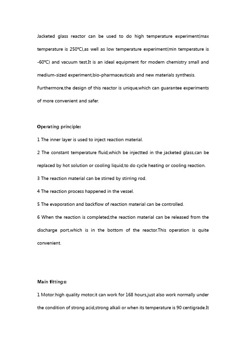
Jacketed glass reactor can be used to do high temperature experiment(max temperature is 250℃),as well as low temperature experiment(min temperature is -60℃) and vacuum test.It is an ideal equipment for modern chemistry small and medium-sized experiment,bio-pharmaceuticals and new materials synthesis. Furthermore,the design of this reactor is unique,which can guarantee experiments of more convenient and safer.Operating principle:1 The inner layer is used to inject reaction material.2 The constant temperature fluid,which be injectted in the jacketed glass,can be replaced by hot solution or cooling liquid,to do cycle heating or cooling reaction.3 The reaction material can be stirred by stirring rod.4 The reaction process happened in the vessel.5 The evaporation and backflow of reaction material can be controlled.6 When the reaction is completed,the reaction material can be released from the discharge port,which is in the bottom of the reactor.This operation is quite convenient.Main fittings:1 Motor:high quality motor,it can work for 168 hours,just also work normally under the condition of strong acid,strong alkali or when its temperature is 90 centigrade.Itbelongs to VVVF,AC induction motor.Speed constant,no brush,no sparks,security and stable.2 Stirring rod:the material of stirring rod is PTFE of stainless steel 304.The structure of paddle is four-leaf and double-layer,so it is easy to stir evenly.The stirring rod of mini glass reactor is trefoil propeller structure.3 Decentralization of material:flange mouth and PTFE valve,fixed by aluminum flange,and fastened with metal screws.There is no dead corner in the container,so it is easy to outlet the reaction material.Features:1 All of the glass adopts Pyrex,which can ensure good chemical and physical properties.2 If hot oil cycles through the jacketed glass,heating experiments could be done.On the contrary,low temperature experiments can be done if the circulated fluid is cold.3 The heat of reaction could be taken away quickly through water,which cycling in the jacketed glass.4 Large mouth design makes it easy to cleaning,standard mouth makes theassembly and backflow could be chose.5 It can be use as distillation syntheses device.6 Titanium alloy mechanical sealing.So the sealing is more stability,the stirring is more evenly,the rusting is disappearance.There is a fluororubber seal between titanium alloy circle and PTFE.Each glass reactor must through the strict tests before leaving factory,the sealing performance is 0.098Mpa.7 The temperature is measured by PT100 electronic.LCD display makes it is easier and more convenient to measure temperature.Parameters:We guarantee one year warranty for all the reactor.Within one year, any fault caused by non-artificial reason we should maintain it freely.。
反应釜毕业设计开题报告
2000L反应釜设计一选题意义反应釜是广泛应用于石油化工,化学,制药,高分子合成,冶金,环保等领域的重要设备。
因此在工业发展过程中研究反应釜的改进技术会使我们提高工作效率,节省资金和时间。
通过反应釜的设计,有助于学生综合运用所学知识,培养学生的自学能力及查阅相关文献的能力,同时提高计算机绘图能力熟练掌握CAD,提高学生的就业能力。
二国内外相关研究现况与发展趋势反应釜在日常生活或者化工生产等领域应用十分广泛。
因此换热设备的研究备受世界各国政府及研究机构的高度重视。
生产必须严格按照相应的标准加工、检测并试运行。
不锈钢反应釜根据不同的生产工艺、操作条件等不尽相同,反应釜的设计结构及参数不同,即反应釜的结构样式不同,属于非标的容器设备。
不锈钢反应釜广泛应用于石油、化工、橡胶、农药、染料、医药、食品等生产型用户和各种科研实验项目的研究,用来完成水解、中和、结晶、蒸馏、蒸发、储存、氢化、烃化、聚合、缩合、加热混配、恒温反应等工艺过程的容器。
反应釜是综合反应容器,根据反应条件对反应釜结构功能及配置附件的设计。
从开始的进料-反应-出料均能够以较高的自动化程度完成预先设定好的反应步骤,对反应过程中的温度、压力、力学控制(搅拌、鼓风等)、反应物/产物浓度等重要参数进行严格的调控。
反应釜材质一般有碳锰钢、不锈钢、锆、镍基(哈氏、蒙乃尔)合金及其它复合材料。
反应釜可采用SUS304、SUS316L等不锈钢材料制造。
搅拌器有锚式、框式、桨式、涡轮式,刮板式,组合式,转动机构可采用无级变速减速机或变频调速等,可满足各种物料的特殊反应要求。
密封装置可采用填料密封等密封结构。
加热、冷却可采用夹套、半管、盘管等结构,加热方式有蒸汽、电加热、导热油,以满足耐酸、耐高温、耐磨损、抗腐蚀等不同工作环境的工艺需要。
可根据用户工艺要求进行设计、制造。
反应釜是指含铬大于12%的钢种。
反应釜自1912年发明以来取得迅猛发展,至今全球仍以每年3—5%的速度递增。
反应釜英文介绍范文
反应釜英文介绍范文Reactor, also known as a reaction vessel or reaction kettle, is a vital equipment used in various industries for carrying out chemical reactions. It is designed to handle high-pressure,high-temperature, and corrosive conditions to ensure safe and efficient reactions. In this article, we will discuss the design, types, and applications of reactors.Design of Reactors:Reactors are designed with several important features to optimize the reaction process. These include:1. Material of construction: Reactors are constructed with materials that can withstand the specific operating conditions, such as stainless steel, glass-lined steel, or exotic metalslike titanium or hastelloy. The choice of material is based on factors like the reactants, temperature, pressure, and corrosion resistance.2. Heat transfer: Reactors are equipped with heat transfer systems to control temperature during the reaction. This can be achieved through jacketing, internal coils, or external heat exchangers. Proper heat transfer ensures efficient reactions and prevents overheating, which can lead to unwanted side reactionsor even explosion.3. Mixing: Efficient mixing of reactants is crucial for uniform reaction and better yields. Reactors use various mixing mechanisms, such as mechanical agitators, impellers, or magnetic stirrers. The type of mixing depends on factors like reaction type, reactant viscosity, and desired rate of mixing.4. Pressure control: As reactions may require high-pressure conditions, reactors are designed with pressure control systems. This includes safety valves, pressure gauges, and relief mechanisms to prevent excessive pressure buildup and ensure the safety of the reactor and personnel.Types of Reactors:2. Continuous Stirred-Tank Reactors (CSTR): In CSTR, the reactants are continuously fed into the reactor and the products are simultaneously removed. It has a well-mixed tank with a stirring mechanism to ensure uniform reaction. CSTRs are widely used in large-scale production as they allow better control over reaction parameters.4. Fixed-Bed Reactors: Fixed-bed reactors have a catalyst bed through which reactants are passed. The reactants flow over the catalyst, leading to a heterogeneous reaction. Fixed-bed reactors are widely used in petrochemical and petroleum refining industries.Applications of Reactors:Reactors find applications in a wide range of industries, including:1. Chemical Industry: Reactors are extensively used in the chemical industry for the production of various chemicals, pharmaceuticals, polymers, and fuels. Different types ofreactors are used based on the nature of the reaction and desired product.2. Petrochemical Industry: Reactors play a crucial role in the petrochemical industry for the production of fuels and various petrochemical products. They are used in processes like catalytic cracking, reforming, hydrogenation, and polymerization.3. Food Processing: Reactors are used in the food industry for processes like fermentation and enzymatic reactions. Theyare used to produce various food products like yogurt, cheese, beer, and wine.4. Environmental Applications: Reactors are used in environmental applications like wastewater treatment, air pollution control, and solid waste management. These reactors help in the removal of pollutants and harmful substances from wastewater and air.。
反应釜设计(毕业论文doc)
最新精品文档,知识共享!摘要本次设计的搅拌设备是PP聚合釜,聚合釜的结构采用夹套式。
内筒介质为PP、设计压力为1.5MPa;夹套内介质为导热油、设计压力为0.3MPa;主体材质为16MnR;搅拌速度为130r/min。
操作时夹套内的油冷却内筒的物料。
设计方法采用压力容器的常规设计方法,遵循《化工设备》要求,按照GB150-98《钢制压力容器》等技术法规执行,设计内容主要包括设计方案的选择;釜体(内筒和夹套)强度、结构的设计、校核和水压试验;搅拌装置设计与校核;传热装置设计、传动装置设计以及反应釜其他零部件设计等。
聚合釜作为反应容器的一种,其应用前景广泛,尤其是在石油与化工行业中更是得到了广泛的应用。
本次设计的聚合釜混合性能好、能耗低、结构简单、紧凑,占用空间及作业面积较小、操作维修方便、易于使物料形成轴向流型并在彼此之间相互分散,能增大不同物相间的接触面积,大大加快传热和传质过程,能保证石油化工行业连续不间断的生产要求。
关键词:反应釜;聚合釜;搅拌设备;传热装置;最新精品文档,知识共享!AbstractThe design involves the mixing equipment is naphthalene polymerization reactor, polymerization reactor structure with jacket. Naphthalene medium within the tube, the design pressure of 1.5MPa; folder comprising a medium for the oil, the design pressure is 0.3MPa; the main material for the 16MnR; stirring speed 130r/min. Operation, the oil cooling kit folder within the tube material. Pressure vessel design using conventional design methods, follow the "chemical device" requirement, according to GB150-98 "steel pressure vessel" and the implementation of technical regulations, design mainly includes design of the program of choice; kettle body (inner tube and jacket) strength, structural design, check and pressure test; agitator design and verification; heat transfer equipment design, transmission design, and reactor design of other components.Polymerization reactor as a reaction vessel, its wide usage, especially in the oil and chemical industry is widely applied. The design of the polymerization reactor well mixed performance, low energy consumption, simple structure, compact, space and operating smaller, easy maintenance, easy to form axial flow of materials and with each other dispersed in, can increase the The contact area between phases of different materials, greatly speeding up the process of heat and mass transfer, to ensure uninterrupted oil-chemical industry production requirements.Key words:Reactor; polymerization reactor; mixing equipment; heat transfer devices;最新精品文档,知识共享!目录第1章绪论 (3)第2章设计方案的选择及设计参数的确定 (7)2.1 搅拌反应釜类型的选择 (7)2.2 设计参数的确定 (8)2.2.1 设计压力的确定 (8)2.2.2 设计温度的确定 (9)2.2.3 釜体材料的选择 (9)第3章反应釜的结构设计 (11)3.1 釜体的选型及尺寸确定 (11)3.1.1 釜体材料及结构型式的选择 (11)3.1.2 釜体直径及高度计算 (11)3.1.3 釜体厚度计算 (13)3.2 封头的选型及尺寸确定 (15)3.2.1 封头材料及结构型式的选择 (15)3.2.2 封头的厚度计算 (16)第4章反应釜的传热装置 (19)4.1 传热装置的类型及选择 (19)4.2 传热装置的尺寸计算 (20)4.2.1 夹套直径及高度的选择 (20)4.2.2 夹套筒体厚度的计算 (20)4.2.3 夹套封头厚度的计算 (21)第5章反应釜的传动装置 (22)5.1 传动方式 (22)5.1.1 电机的选用 (22)5.1.2 减速机的选用 (23)5.2 传动方式的机座 (23)第6章反应釜的搅拌装置 (25)最新精品文档,知识共享!6.1 搅拌器的类型及选择 (25)6.2 搅拌功率的计算 (26)6.3 搅拌轴的校核 (27)6.3.1 搅拌轴材料的选择 (27)6.3.2 搅拌轴的强度校核 (27)6.3.3 搅拌轴的刚度校核 (28)第7章反应釜的密封与其他附件 (30)7.1 反应釜的密封装置 (30)7.2 设备的支座 (32)7.3 联轴器的选用 (32)7.4 法兰的选用及校核 (33)7.5 容器的开孔与补强 (36)7.5.1 开孔补强的设计与补强结构 (36)7.5.2 开孔补强的计算 (40)参考文献 (44)致谢 (46)最新精品文档,知识共享!第1章绪论在生产实践中,许多化工生产过程都需要反应设备,广泛应用于物料混合、溶解、传热、制备悬浮液、聚合反应和制备催化剂等生产过程。
100TPD植物油反应釜设计外文资料翻译(有全套CAD图纸)
毕业设计(论文)外文资料翻译题目: ActiveX and VBA Reference院系名称:专业班级:学生姓名:学号:指导教师:教师职称:起止日期:地点:原文Activate eventTriggered when a document window is activated.See Also | ExampleSignatureobject.Activate()objectDocument objectAn object expression that evaluates to a valid container object. In this case, the only valid container is a document.RemarksNo events will be fired while a modal dialog is being displayed.See AlsoMethods, Properties, and Events:AppActivateWindowMovedOrResizedActiveX and VBA Developer's Guide:"Use Events"ExamplePrivate Sub AcadDocument_Activate()' This example intercepts a drawing Activate event.'' This event is triggered when a drawing window becomes active.' ' To trigger this example event: Either open a new drawing or switch from one drawing window to anotherMsgBox "You have just activated a drawing!"End SubAppActivate EventTriggered just before the main application window is activated.See Also | ExampleSignatureobject.AppActivate()objectApplicationAn object expression that evaluates to a valid container object. In this case, the only valid container is the application.RemarksNo events will be fired while a modal dialog is being displayed.See AlsoMethods, Properties, and Events:AppDeactivateWindowMovedOrResizedActiveX and VBA Developer's Guide:"Use Events"ExamplePublic WithEvents ACADApp As AcadApplication ' Use with Application Event ExamplesSub Example_AcadApplication_Events()' This example initializes the public variable (ACADApp), which will be used to intercept AcadApplication Events '' The VBA WithEvents statement makes it possible to intercept a generic object with the events associated with that object.' ' Before you will be able to trigger any of the AcadApplication events, you will need to run this procedure.' We could get the application from the ThisDocument object, but that would require having a drawing open, so we get it from the system.Set ACADApp = GetObject(, "AutoCAD.Application.16")End SubPrivate Sub ACADApp_AppActivate()' This example intercepts an Application AppActivate event.'' This event is triggered when the AutoCAD application receives focus'' To trigger this example event:' 1) Make sure to run the example that initializes' the public variable (named ACADApp) linked to this event.'' 2) Switch focus from AutoCAD to another Windows application and then back again.MsgBox "AutoCAD was just activated!"End SubAppDeactivate eventTriggered just before the main application window is deactivated.See Also | ExampleSignatureobject.AppDeactivate()objectApplicationAn object expression that evaluates to a valid container object. In this case, the only valid container is the application.RemarksNo events will be fired while a modal dialog is being displayedSee AlsoMethods, Properties, and Events:AppActivateWindowMovedOrResizedActiveX and VBA Developer's Guide:"Use Events"ExamplePublic WithEvents ACADApp As AcadApplication ' Use with Application Event ExamplesSub Example_AcadApplication_Events()' This example initializes the public variable (ACADApp), which will be used to intercept AcadApplication Events.'' The VBA WithEvents statement makes it possible to intercept a generic object with the events associated with that object.'' Before you will be able to trigger any of the AcadApplication events, you will first need to run this procedure.' We could get the application from the ThisDocument object, but that would require having a drawing open, so we get it from the system.Set ACADApp = GetObject(, "AutoCAD.Application.16")End SubPrivate Sub ACADApp_AppDeactivate()' This example intercepts an Application AppDeactivate event.'' This event is triggered when the AutoCAD application loses focus'' To trigger this example event:' 1) Make sure to run the example that initializes' the public variable (named ACADApp) linked to this event.' ' 2) Switch focus from AutoCAD to another Windows application. MsgBox "AutoCAD just lost focus!"End SubARXLoaded eventTriggered when an ObjectARX application has been loaded.See Also | ExampleSignatureobject.ARXLoaded(FullPathName)objectApplicationAn object expression that evaluates to a valid container object. In this case, the only valid container is the application.FullPathNameStringThe full path and file name of the ObjectARX application that has been loaded.RemarksNo events will be fired while a modal dialog is being displayedSee AlsoMethods, Properties, and Events:ARXUnloadedActiveX and VBA Developer's Guide:"Use Events"ExamplePublic WithEvents ACADApp As AcadApplication ' Use with Application Event ExamplesSub Example_AcadApplication_Events()' This example initializes the public variable (ACADApp), which will be used to intercept AcadApplication Events.'' The VBA WithEvents statement makes it possible to intercept a generic object with the events associated with that object.'' Before you will be able to trigger any of the AcadApplication events, you will first need to run this procedure.' We could get the application from the ThisDocument object, but that would require having a drawing open, so we get it from the system.Set ACADApp = GetObject(, "AutoCAD.Application.16")End SubPrivate Sub ACADApp_ARXLoaded(ByVal AppName As String)' This example intercepts an Application ARXLoaded event.' This event is triggered when AutoCAD loads an ObjectARX application.'' To trigger this example event:' 1) Make sure to run the example that initializes' the public variable (named ACADApp) linked to this event.' ' 2) Load an ARX application into AutoCAD.' Use the "AppName" variable to notify the user which ARX application was loadedMsgBox "AutoCAD just loaded the ARX application: " & AppName End SubARXUnloaded eventTriggered when an ObjectARX application has been unloaded.See Also | ExampleSignatureobject.ARXUnloaded(FullPathName)objectApplicationAn object expression that evaluates to a valid container object. In this case, the only valid container is the application.FullPathNameStringThe full path and file name of the ObjectARX application that has been unloaded.RemarksNo events will be fired while a modal dialog is being displayed. See AlsoMethods, Properties, and Events:ARXLoadedActiveX and VBA Developer's Guide:"Use Events"ExamplePublic WithEvents ACADApp As AcadApplication ' Use with Application Event ExamplesSub Example_AcadApplication_Events()' This example intializes the public variable (ACADApp) which will be used to intercept AcadApplication Events'' The VBA WithEvents statement makes it possible to intercept an generic object with the events associated with that object.'' Before you will be able to trigger any of the AcadApplication events, you will first need to run this procedure.' We could get the application from the ThisDocument object, but that would require having a drawing open, so we grab it from the system.Set ACADApp = GetObject(, "AutoCAD.Application.16")End SubPrivate Sub ACADApp_ARXUnloaded(ByVal AppName As String)' This example intercepts an Application ARXUnloaded event.'' This event is triggered when the AutoCAD unloads an ARX application'' To trigger this example event:' 1) Make sure to run the example that initializes' the public variable (named ACADApp) linked to this event.' ' 2) Unload an ARX application that is already loaded into AutoCAD' Use the "AppName" variable to notify the user which ARX application was unloadedMsgBox "AutoCAD just unloaded the ARX application: " & AppName End Sub译文Activate 事件当一个文档窗口激活时被触发。
- 1、下载文档前请自行甄别文档内容的完整性,平台不提供额外的编辑、内容补充、找答案等附加服务。
- 2、"仅部分预览"的文档,不可在线预览部分如存在完整性等问题,可反馈申请退款(可完整预览的文档不适用该条件!)。
- 3、如文档侵犯您的权益,请联系客服反馈,我们会尽快为您处理(人工客服工作时间:9:00-18:30)。
Welding Simulation of Cast Aluminium A356X-T. Pham*, P. Gougeon and F-O. GagnonAluminium Technology Centre, National Research Council Canada Chicoutimi, Quebec, CanadaAbstractWelding of cast aluminium hollow parts is a new promising technical trend for structural assemblies. However, big gap between components, weld porosity, large distortion and risk for hot cracking need to be dealt with. In this paper, the MIG welding of aluminium A356 cast square tubes is studied. The distortion of the welded tubes was predicted by numerical simulations. A good agreement between experimental and numerical results was obtained.IntroductionAluminium structures become more and more popular in industries thanks to their light weights, especially in the automotive manufacturing industry. Moreover, welding of cast aluminium hollow parts is a new promising technical trend for structural assemblies [1-3]. However, it may be very challenging due to many problems such as big gap between components, weld porosity, large distortion and risk for hot cracking [4,5]. Due to local heating, complex thermal stresses occur during welding; residual stress and distortion result after welding. In this paper, the aluminium A356 cast tube MIG welding is studied. The software Sysweld [6] was used for welding simulations. The objective is to validate the capability of this software in predicting the distortion of the welded tubes in the presence of large gaps. In this work, the porosity of welds was checked after welding using the X-ray technique. The heat source parameters were identified based on the weld cross-sections and welding parameters. Full 3D thermal metallurgical mechanical simulations were performed. The distortions predicted by the numerical simulations were compared to experimental results measured after welding by a CMM machine.ExperimentsExperimental setupTwo square tubes are made of A356 by sand casting and then machined. They are assembled by four MIG welds, named W1 to W4. Their dimensions and the welding configuration are depicted in Figure 1. Both small (inner) and large (outer) tubes are well positioned on a fixture using v-blocks as shown in Figure 2. The dimensions of the tubes make a peripheral gap of 1 mm between them. This fixture is fixed on a positioner that allows the welding process to be carried out always in the horizontal position. The length of each weld is of 35 mm. The Fronius welding head, which is mounted on a Motoman robot, was used for the MIG welding process. Table 1 indicates the parameters of the welding process forthis welding configuration.a)b)Figure 1: Tube welding configuration: a) cross-section view, b) tube dimensionsFigure 2: Experimental setup for tube weldingTestingThe porosity of welds was observed before and after welding using the X-ray technique to check the quality of these welds according to the standard ASTM E155. The whole welded tubes were then tested by traction on a MTS testing machine. The final dimensions of the welded tubes are measured on a CMM machine at many points on the tubes. The distortion of the welded tubes is determined by comparing the final positions with the initial positions of the tubes.Numerical analysisIn Sysweld, a welding analysis is performed based on a weak-coupling formulation between the heat transfer and mechanical problems. Only the thermal history will affect on the mechanical properties, but not in reverse direction. Therefore, a thermal metallurgical mechanical analysis is divided into two steps. The first step is a thermal metallurgical analysis, in which the heat transferred from the welding source makes phase changes during the welding process. The results of temperature and phase changes from the first step are then used as input for the second analysis. It is a pure thermo-elasto-plastic simulation [6].Heat source model identificationBefore running a welding simulation, it is necessary to determine the parameters of the heat source model. This is called heat source fitting. Actually, it is a thermal simulation using this heat source model in the steady state, which iscombined with an optimization tool to obtain the parameters of the heat source. Figure 3 presents the form of a 3D conical heat source of which the energy distribution is described in Eq (1) as follows:F=Q0exp(-r²/r0²) (1)in which Q0 denotes the power density; and r,r0 are defined byr²=(x-x0)²+(x-x0-v t)²(2)andr0=r e-(r e-r i)(z e-z+z0)/(z e-z i) (3)where(x0,y0,z0)is the origin of the local coordinate system of the heat source; r e and r i the radius of the heat source at the positions z e and z i,respectively;v the welding speed and t the time.In this study, a metallographic cross-section has been used to identify the heat source parameters as shown in Figure 4. The use of a 3D conical heat source fits very well the weld cross-section. The mesh size in the cross-section is around 0.5 mm for this case. The finer is the mesh, the more accurate is the shape of the melting pool, but the longer is the simulation.Figure 3: 3D conical heat source (Sysweld).a)b)Figure 4: (a) Metallographic cross-section, (b) Melting pool cross-section.Analysis modelThe mesh of the tubes was created in Hypermesh 7.0. Sysweld 2007 has been used as solver and pre/post processor. A full 3D thermal metallurgical mechanical analysis with brick and prism elements. Two welding sequences have been done such as W1/W2/W3/W4 and W1/W3/W2/W4. The tubes are clamped using four v-blocks during the welding, two for each tube. In the simulations, the positions where the tubes are in contact against the surfaces of the v-blocks are considered as fixed conditions (i.e. Ux = Uy = Uz = 0). In the release phase, the tubes are free from the v-blocks.ResultsThe distortion of the welded tube is measured when it is released from the constraints. The distortion is determined by measuring the displacement of the small tube on the top andlateral surfaces along the centre line of the tube. These measures are relative to the large tube. Figures 5a-b depict the distortion predicted by the numerical simulations of the sequence W1/W2/W3/W4 and W1/W3/2/W4, respectively. Good agreements between experimental and numerical results were obtained in the two welding sequences as indicated in Tables 2-3, in both the distortion tendency and distortion range of the process variation.a)b)Figure 5: Tube distortion (Norm U): (a) Sequence W1/W2/W3/W4, (b) Sequence W1/W3/W2/W4.Table 2: Distortion result comparison (welding sequence W1/W2/W3/W4)a)b)Figure 7: State of stresses Sxy (a) Clamped, (b) Released. (Red = positive, Blue = negative)a)b)Figure 8: State of stresses Sxz (a) Clamped, (b) Released. (Red = positive, Blue = negative) Figures 6-8 shows the state of the stresses of the welded tubes at room temperature for the sequence W1/W2/W3/W4 after welding when clampled and released from constraints (x is the direction along the axe of the welded tube). To show how the welded tube is distorted, positive-negative values are used instead of the true values of stresses. The distortion of the welded tube can be explained as the new equilibrium position due to the residual stresses when there is no external load. It is remarked that in the presence of large gaps, the distortion of the welded tube is very likely in the rotational mode around local welds.ConclusionsThe MIG welding is very good for assembling aluminium cast tubes (hollow parts) in the presence of large gaps.The 3D thermal metallurgical mechanical simulation of the cast tube welding using Sysweld has been validated. A very good agreement between numerical and experimental results was obtained for both the distortion tendency and distortion range.The welding sequence has a major influence on the distortion of the welded structure. It turns out that the optimization of the welding sequences for a reasonable distortion of a welded structure with a large number of welds becomes very important.AcknowledgmentsThe authors would like to thank gratefully Rio Tinto Alcan and General Motor for financial and technical supports, particularly Martin Fortier and Pei-Chung Wang. Also, the authors are grateful to Welding Team at ATC (Audrey Boily, Martin Larouche, François Nadeau and Mario Patry) for experimental works.References1. K-H. Von Zengen, Aluminium in future cars – A challenge for materials science, Materials Science Forum, 519-521 (Part 2), 1201-1208 (2006).2. S. Wiesner S., M. Rethmeier and H. Wohlfart, MIG and laser welding of aluminium alloy pressure die cast parts with wrought profiles, Welding International, 19 (2), 130-133 (2005).3. R. Akhter, L. Ivanchev, C.V.Rooyen, P. Kazadi and H.P. Burger, Laser welding of SSM Cast A356 aluminium alloy processed with CSIR-Rheo technology, Solid State Phenomena, 116-117, 173-176 (2006).4. J.F. Lancaster, Metallurgy of welding, Abington Publishing (1999).5. Φ. Grong, Metallurgical modelling of welding, The institute of materials (1997).6. Sysweld, Sysweld reference manual, ESI Group (2005).译文铸造A356铝合金的焊接模拟X-T. Pham*, P. Gougeon and F-O. GagnonAluminium Technology Centre, National Research Council Canada Chicoutimi, Quebec, Canada摘要:空心铝铸造件的焊接是一个很有前途的新结构组件技术的趋势。