HP-DP官方日常维护手册
激光打印机维护保养完全手册范本
一、激光打印机维护保养完全手册激光打印机是现代办公不行缺少的办公设备,它的使用为宽阔的办公用户带来了很大便利,同时也大大提高了办公效率。
大家在使用激光打印机时,除了要知道简洁的操作步骤外,还要对打印机的维护、正确的使用及常见故障的解决有所了解,这样才会更好的利用激光打印机为日常办公工作效劳。
一、打印机常见部件的维护激光打印机自身吸附灰尘的力量很强,在打印工作时不行避开地会有一些粉尘残留在机内的一些部件上。
由于激光打印机热量会将这些粉尘粉尘变成坚硬的固体,从而影响到激光打印机的正常使用,甚至使激光打印机发生故障。
激光打印机需要维护的部件包括电极丝、激光扫描系统、定影器局部、分别爪及硒鼓等。
1、电板丝的维护电极丝沾污了废粉、纸灰等,会使打印出来的印件墨色不够、纸样反面脏污或输出的打印件底灰严峻。
维护电极丝时应留神地取出电极丝组件,有些型号的打印机不必取出电极丝,可直接在机子上进展清洁,可以先用毛刷刷掉其上附着的异物,然后再用脱脂棉花将其轻轻地认真擦拭干净。
2、扫描系统的维护激光扫描系统中的激光器及各种镜片被粉尘等污染后,会造成打印件底灰增加,图象不清。
可用脱脂棉将它们擦拭干净,如不行可用脱脂棉醮少许酒精擦拭干净,擦拭时肯定要留意不能转变它们的原有位置或碰坏。
3、定影辊的维护定影加热辊在长期使用后可能粘上一层墨粉等脏物,就会影响打印效果,如消灭黑块、黑条等。
与加热辊相配对的橡皮辊,长期使用后也会粘上废粉,一般较稍微时不会影响输出效果,但假设严峻时,会使输出的样稿反面变脏。
这时就需要清洁加热辊和橡皮辊,可用脱脂棉蘸无水酒精留神地将其擦拭干净。
但不行太用力擦拭加热辊,橡皮辊的擦拭可简洁一些,只需将其外表擦干净即可。
4、分别爪的维护分别爪是紧靠加热辊的小爪,主要作用是分别纸张,避开纸与热辊相粘而卡纸,其爪尖长期与加热辊和纸张摩擦,可能会粘上废粉结块,从而使纸张输出时变成弯曲褶皱状,甚至引起卡纸。
因此,如觉察输出纸张有褶皱时应留意清洁分别爪。
HP产品用户手册说明书

ErrataTitle & Document Type:Manual Part Number:Revision Date:HP References in this ManualThis manual may contain references to HP or Hewlett-Packard. Please note that Hewlett-Packard's former test and measurement, semiconductor products an d chemical analysis businesses are now part of Agilent Technologies. We have made no changes to this manual copy. The HP XXXX referred to in this document is now the Agilent XXXX. For example, model number HP8648A is now model number Agilent 8648A.About this ManualWe’ve added this manual to the Agilent website in an effort to help you support your product. This manual provides the best information we could find. It may be incomplete or contain dated information, and the scan quality may not be ideal. If we find a better copy in the future, we will add it to the Agilent website.Support for Your ProductAgilent no longer sells or supports this product. You will find any other available product information on the Agilent Test & Measurement website:Search for the model number of this product, and the resulting product page will guide you to any available information. Our service centers may be able to perform calibration if no repair parts are needed, but no other support from Agilent is available.1981400GL AC Voltmeter Operating and Service Manual 00400-90008September 1969。
惠普打印机维修手册

惠普打印机维修手册/激光打印机维修手册来源:郑州乐泰科技作者:周东营【大中小】浏览:232次评论:0条HP 激光打印机 1 。
HP 4000/4050/4100/5000 (1) 按" 项目" 键左端加" 数值" 键左端开机。
(2) 当液晶屏上出现"RESET MAINTENANCE COUNT"( 重设计数器) 时,松开各键。
2 。
HP 4500/4550 (1) 按住" 取消" 键和" 选择" 键开机,当液晶亮起来时,松开二键。
(2) 按住" 数值" 键的右端,然后按" 选择" 键。
(3) 你将在完成正常自检后进入"SERVICE MODE"( 服务模式) 。
(4) 按" 项目" 键找到"FUSER MAINTENANCE COUNT"( 这句我翻译成加热组件保养计数器不知当否?) (5) 按" 数值" 键找到"0" (6) 按" 选择" 键保存。
(7) 按" 执行" 键机器返回ready 状态。
3 。
HP COLOR LASERJET 4500/4550 (TRANSFER KIT RESET) 传送单元重置(1) 按" 菜单" 找到"RESET MENU" (2) 按" 项目" 键找到"TRANSFER KIT SELECT IF DONE"( 传送单元已好) (3) 按" 选择" 键。
(4) 按" 执行键" 机器返回ready 状态。
4 。
HP COLOR LASERJET 4500/4550 (FUSER KIT RESET) 加热组件重置(1) 按" 菜单" 找到"RESET MENU" (2) 按" 项目" 键找到"FUSER KIT SELECT IF DONE"( 加热组件已好) (3) 按" 选择" 键。
HP DP备份软件与2024带库简单配置手册
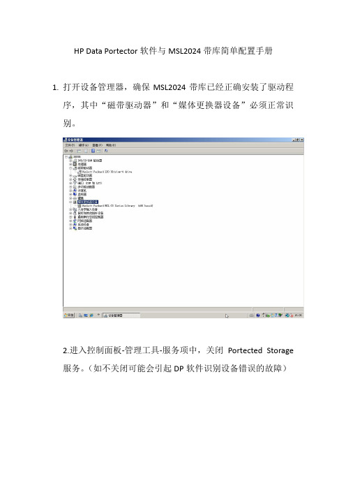
HP Data Portector软件与MSL2024带库简单配置手册1.打开设备管理器,确保MSL2024带库已经正确安装了驱动程序,其中“磁带驱动器”和“媒体更换器设备”必须正常识别。
2.进入控制面板-管理工具-服务项中,关闭Portected Storage服务。
(如不关闭可能会引起DP软件识别设备错误的故障)2.安装HP Data Protector软件。
4.双击图标Data Protector Manager进入软件菜单。
5.从软件左上角下拉菜单中选择Clients选项,选择Clients 单机鼠标右键选择Add Clients(添加客户端),从而添加与磁带库相连接的服务器。
6. 从软件左上角下拉菜单中选择Devices & Media选项,在Devices by host选项中单击鼠标右键,选择Autoconfigure Devices(自动添加设备)选项,并选择识别到的设备。
7.设备添加完成后,选择Slots并单击右键,执行Barcode Scan(条码扫描),完成后会识别出槽位磁带状态。
8.选择有问号的槽位图标,单击右键执行Scan和Format。
直到磁带被正确识别(绿色磁带图标)。
注意:在执行Format 命令时,要勾选Force operation选项(强制格式化)9. 从软件左上角下拉菜单中选择Backup选项,选择Backup Specifications下的Filesystem,单击右键执行Add Backup命令。
10.勾选需要备份的文件位置并选择执行设备。
11.设置备份策略。
(备份时间和备份方式,全备选择Full,增量选择Incr)。
12.保存备份策略,如想立即执行可选择备份策略右键Start Backup。
惠普升级和维修指南说明书
Upgrading and Servicing GuideThe information in this document is subject to change without notice.Hewlett-Packard® Company makes no warranty of any kind with regard to this material, including, but not limited to, the implied warranties of merchantability and fitness for a particular purpose.HP shall not be liable for errors contained herein or for incidental or consequential damages in connection with the furnishing, performance, or use of this material.HP assumes no responsibility for the use or reliability of its software on equipment that is not furnished by HP.This document contains proprietary information that is protected by copyright. All rights are reserved. No part of this document may be photocopied, reproduced, or translated to another language without the prior written consent of HP.Hewlett-Packard CompanyP.O. Box 4010Cupertino, CA 95015–4010USACopyright © 2004, 2005 Hewlett-Packard Development Company, L.P.All rights reserved.This product incorporates copyright protection technology that is protected by method claims of certain U.S. patents and other intellectual property rights owned by Macrovision Corporation and other rights owners. Use of this copyright protection technology must be authorized by Macrovision Corporation, andis intended for home and other limited viewing uses only unless otherwise authorized by Macrovision Corporation. Reverse engineering or disassembly is prohibited. Apparatus Claims of U.S. Patent Nos. 4,631,603, 4,577,216,4,819,098, and 4,907,093 licensed for limited viewing uses only.Microsoft and Windows are U.S. Registered trademarks of Microsoft Corporation.HP supports lawful use of technology and does not endorse or encourage the use of our products for purposes other than those permitted by national copyright law.Table of ContentsSafety Information (1)Opening and Closing the PC (1)Preparing the PC (1)Before Opening the PC (1)After Closing the PC (2)Removing the Side Panel (2)Replacing the Side Panel (2)Removing the Front Panel (2)Replacing the Front Panel (3)Locating Components Inside the PC (3)Removing and Replacing Drives (3)Removing a Drive (4)Replacing or Adding a Drive (5)Adding Memory (7)Removing a Memory Module (7)Installing a Memory Module (8)Removing or Installing an Add-In Card (8)Removing an Add-In Card (9)Installing an Add-In Card (9)Replacing the Battery (10)Upgrading and Servicing Guide iiiiv Upgrading and Servicing GuideSafety InformationThis product has not been evaluated for connection to an “IT” power system (an AC distribution system with no direct connection to earth, according toIEC 60950).WARNING: Please read “SafetyInformation” in the Warranty and SupportGuide before installing and connectingyour system to the electrical powersystem.Opening and Closing the PCPreparing the PCBefore you upgrade any component in your PC, you need to prepare the PC so that you can safely handle it and the components.Read the following items before attempting to upgrade or service the PC.• These procedures assume familiarity with the general terminology associated with personalcomputers and with the safety practices andregulatory compliance required for using andmodifying electronic equipment. • Write down and save the system model and serial numbers, all installed options, and otherinformation about the system. It’s easier to consult this information than to open up and examinethe PC.• It is recommended that you use an antistatic wrist strap and a conductive foam pad when working on the system.WARNING: Always disconnect the modemcord from the telephone system, and thendisconnect the PC from the power sourcebefore removing the front and side panelsof the PC. Failure to do so before youopen the PC or do any procedures canresult in personal injury or equipmentdamage.Before Opening the PC1 Remove any diskette or optical disc (CD or DVD)from the PC.2 Click the Start button, and then click Turn OffComputer. Click Turn Off.3 Disconnect the modem/telephone cable, if present.CAUTION: To reduce the risk of personalinjury from electrical shock or hotsurfaces, disconnect the power cord fromthe wall outlet, and allow the internalsystem components to cool beforetouching.4 Disconnect the power cord from the electrical outletand then from the PC.5 Disconnect all other attached cables (such as thekeyboard, mouse, and monitor) and all externaldevices.CAUTION: Static electricity can damagethe electronic components of the PC oroptional equipment. Ensure that you aredischarged of static electricity by brieflytouching a grounded metal object.Upgrading and Servicing Guide 12 Upgrading and Servicing GuideAfter Closing the PCTo avoid injury and equipment damage, alwaysfollow this procedure in this order after closing the PC. 1 Reconnect the power cord.WARNING: To reduce the risk of electrical shock, fire, or damage to the equipment, do not plug telecommunications or telephone connectors into the network interface card (NIC) (labeled as an Ethernet connector).2 Reconnect the modem/telephone cable, and all other cables (such as the keyboard, mouse, and monitor) and external devices.3 Turn on the PC and all peripherals.4 If you installed an add-in card, install any software drivers supplied by the card manufacturer.Removing the Side Panel1 Remove the side panel by loosening the screw (D ) that secures the panel to the PC chassis.Replacing the Side Panel1 Place the side panel in the proper position on the chassis and slide it into place.2 Ensure that the hole for the thumbscrew aligns with the hole in the chassis, and replace the thumbscrew (D ).1) near the 3), toward the 2 Remove the front panel.Replacing the Front Panel1 Align the top of the front panel with the top of thechassis front.2 Press the panel onto the chassis at the top and ateach side near the bottom until the panel snaps into place.Locating Components Inside the PCA Upper optical drive bay, may be a CD-ROM, CD-RW,DVD-ROM, DVD+RW/+R, or combination driveB Lower optical drive bay, may be empty (blank plate) or aCD-ROM, CD-RW, DVD-ROM, DVD+RW/+R, orcombination driveC Memory card reader (select models)D Diskette (floppy) drive (select models)E Front connector panel (no replacement instructions)F Hard disk driveG Second hard disk drive (select models) Removing and Replacing DrivesYour PC has several drives that you can replace or upgrade. See the preceding topic, “Locating Components Inside the PC,“ for drive type and location.The hard disk drive is either a Serial ATA (advanced technology attachment) drive that uses a narrow data cable, or a Parallel ATA drive that uses a wide data cable.Select models have a second hard disk drive.CAUTION: Back up your personal files onthe hard disk drive to an externalstorage device, such as a CD, beforeremoving the hard disk drive. Failure todo so will result in data loss. Afterreplacing the hard disk drive, you needto run System Recovery using therecovery discs to load the factory-installed files. See the userdocumentation that came with your PCfor details about the recovery procedure. You can add an optical drive into an empty lower optical drive bay.IMPORTANT: Before adding a new optical drive, make sure that it is compatible with the Microsoft®Windows® XP operating system. Also, make sure you have the correct software and drivers for the optical drive to work with the operating system.Upgrading and Servicing Guide 35 Push down the two retaining clips on the ends ofthe memory socket until the memory module pops out of the socket.WARNING: Do not pull the memorymodule out of the socket. Use theretaining clips to eject the module.6 Lift the memory module from the memory socket.Installing a Memory Module Upgrade the memory in your PC with memory of the same type and speed as the memory originally installed in your PC.CAUTION: When handling a memorymodule, be careful not to touch any ofthe contacts. Doing so may damage themodule.1 Open both latches of the memory module socket: • If you are replacing a memory module, put the new memory module in the same memory slotfrom which the old memory was removed.Or• If you are adding a memory module, install the new module into the socket nearest thepreinstalled module, and install additionalmodules in the next available sockets.2 The memory module can be installed in only oneway. Match the notch on the module with the tabon the memory socket (B). Push the modulecarefully and firmly into the slot, ensuring that the latches on both ends snap into place.3 Set the chassis upright.4 Complete the procedures to replace the side panel,and close the PC. See “Opening and Closing the PC“ on page 1.NOTE: If a blank screen is displayed after replacing or adding a memory module, the memory is installed incorrectly or it is the wrong type of memory. Remove and reinstall the memory module.Removing or Installing an Add-In CardAn add-in card is a circuit board, such as a PCI or an AGP card, that fits into a PC add-in card slot. Your PC contains several add-in card slots that can be used to add components to your PC. The PC component configurations vary by model.WARNING: Do not overload the systemby installing add-in cards that drawexcessive current. The system is designedto provide 2 amps (average) of +5 Vpower for each board/card in thecomputer. The total +5 V current draw ina fully loaded system (one with all add-incard slots filled) must not exceed the totalnumber of slots multiplied by 2 amps.A Phillips screwdriver is needed to remove, replace, or add an add-in card.8 Upgrading and Servicing GuideUpgrading and Servicing Guide 9Removing an Add-In Card1 Complete the procedures to prepare the PC and to remove the side panel. See “Opening and Closing the PC“ on page 1.2 Gently lay the PC on its side.3 On the back of the PC, remove the screw from the bracket cover for the add-in card slots, and then remove the bracket cover.4 Inside the PC, locate the add-in card slots on the motherboard.6 If you are not replacing the old add-in card with a new add-in card, close the open slot by inserting the metal slot cover into the opened slot.Installing an Add-In Card1 Align the edge of the add-in card with the slot on the chassis and gently but firmly press the card straight down into the add-in card slot. The whole connector should be seated properly in the card slot.Replacing the BatteryA lithium battery on the motherboard provides backup power for the PC’s timekeeping capability. The battery has an estimated life expectancy of seven years. When the battery starts to weaken, the date and time may be incorrect. If the battery fails, replace it with a CR2032 lithium battery (3 volt, 220mAH rating) or an equivalent battery.WARNING: There is danger of explosionif the battery is incorrectly replaced.Replace only with the same, orequivalent, type of battery. Discard usedbatteries according to the manufacturer’sinstructions.1 Complete the procedures to prepare the PC and toremove the side panel. See “Opening and Closing the PC“ on page 1.2 Gently lay the PC on its side.3 Remove any cabling, if necessary, to reach thebattery.4 Remove any memory modules, if necessary, toreach the battery. See “Adding Memory“ onpage 7.5 To remove the battery, push the latch away from thebattery and lift the battery from the socket.6 Install the new CR2032 battery in the socket, withthe positive (+) side facing the latch.7 Replace memory modules or cables you removed.8 Set the chassis upright.9 Complete the procedures to replace the side panel,and to close the PC. See “Opening and Closing the PC“ on page 1.10 Upgrading and Servicing GuideUpgrading and Servicing Guide 11Printed in。
惠普支持中心 用户指南说明书

惠普支持中心用户指南文档发行日期:2015年3月软件发行日期:2015年3月法律声明保修HP产品与服务的唯一保证发布于此类产品与服务随附的明确保修声明中。
此处的声明不应视为额外的保证。
对此处包含的技术或编辑错误或遗漏,HP概不负责。
包含在本文档中的信息如有变更,恕不另行通知。
有限权利声明机密计算机软件。
拥有、使用或复制均需取得HP的有效授权。
根据FAR12.211和12.212,商业计算机软件、计算机软件文档和商业项目技术数据均依照供应商的标准商用授权而授予给美国政府。
版权声明©版权所有2015Hewlett-Packard Development Company,L.P.商标声明Adobe®是Adobe Systems Incorporated的商标。
Microsoft®和Windows®是Microsoft Corporation在美国的注册商标。
UNIX®是The Open Group的注册商标。
目录关于惠普支持中心6创建HP Passport帐户7查找您的产品8产品特定内容9搜索12高级搜索13过滤器16安全公告档案16保存搜索17部分匹配17 NonStop搜索17按文档ID搜索18设置19我的惠普支持中心访问19查找驱动程序和其他软件21确定您的操作系统22如果操作系统未列出23如果无法找到所需文件23查找咨询、公告和通知24查找查看次数最多的解决方法查找产品手册27查找产品常见问题支持案例管理器31提交案例32提供案例详细信息33预期响应时间35检查案例状态35查看案例报告35查看案例详细信息37更新案例37向案例添加备注37向案例添加附件37关闭案例38编辑SCM设置38保修信息查询39访问要求40序列号和产品编号的位置40未找到保修信息或返回了错误41如何延期或升级保修41补丁程序管理42我的补丁程序权限43任意系统的补丁程序44按产品查找补丁程序46补丁程序捆绑包47将捆绑包添加到补丁程序列表47选定补丁程序列表47下载补丁程序49文件指纹50损坏的下载存档50我上传的HP-UX系统的补丁程序51其他可用的补丁程序51更多信息: HP-UX、OpenVMS、Tru64、MPE/iX51诊断密码52客户自行维修53检查是否符合条件53确定自行更换选项类型53订购部件55状态和协助55说明和视频56从惠普获得帮助58语言和国家选择器索引62关于惠普支持中心关于惠普支持中心惠普支持中心为大部分惠普商业和企业产品提供支持信息和功能。
HP产品用户指南.pdf_1701991487.68381说明书

摘要本指南提供有关组件、网络连接、电源管理、安全性和备份等相关信息。
法律信息©Copyright 2022 HP Development Company, L.P.Windows 是 Microsoft Corporation 在美国和/或其他国家/地区的注册商标或商标。
USB Type-C 和 USB-C 是 USB Implementers Forum 的注册商标。
DisplayPort™ 和 DisplayPort™ 徽标是 Video Electronics Standards Association (VESA) 在美国和其他国家/地区所有的商标。
本文所含信息如有更改,恕不另行通知。
HP 产品和服务附带的明示保修声明中阐明了此类产品和服务的全部保修服务。
本文档中的任何内容均不构成任何额外保修。
HP 对本文档中出现的技术错误、编辑错误或遗漏之处不承担任何责任。
第一版:2022 年 2 月文档部件号:N01984-AA1产品通告本指南介绍大多数产品共有的功能。
您的计算机上可能未提供某些功能。
并非所有功能在所有 Windows 版本中都可用。
系统可能需要升级和/或单独购买硬件、驱动程序、软件或 BIOS 更新,才能充分利用Windows 功能。
Windows 会自动更新,此功能始终处于启用状态。
需要高速互联网和Microsoft 帐户。
可能会收取 ISP 费用,在更新过程中可能还会有其他要求。
请参阅。
如果您的产品出厂随附 S 模式的 Windows:S 模式的Windows 仅适用于来自 Windows 的 MicrosoftStore 中的应用。
某些默认设置、功能和应用不能更改。
某些兼容 Windows 的配件和应用程序可能无法运行(包括某些防毒软件、PDF 编写器、驱动程序实用程序和辅助功能应用程序)。
而且,即使您退出 S 模式,性能也可能会有所不同。
如果切换至Windows,则无法再切换回 S 模式。
HP DP
12
Users模块
u1610s b.00
© 2003 Hewlett-Packard Development Company, L.P.
13
Users模块的三种模式
DP有三种缺省模式,用户可根据自己的实际使用情况添加用户, 还可以自定义组
Admin
Operator
User
u1610s b.00
© 2003 Hewlett-Packard Development Company, L.P.
u1610s b.00
X X X X X X X X X X X X X X
X
© 2003 Hewlett-Packard Development Company, L.P.
18
Devices & Media模块
u1610s b.00
© 2003 Hewlett-Packard Development Company, L.P.
HP OpenView Storage Data Protector
日常维护手册
版本号:1.0
要点