美国RMYOUNG05103风速风向仪传感器用户手册EN(威瑞贸易)
风向和风速仪用户手册

编号: NLT-AM706-SSCN版本号:V120619风向和风速仪 用户手册 型号: AM706***快速使用指南***¾失电报警:一路电源掉电时,主机失电报警,按主机上任意键消除报警。
¾【F】键:相对风速+航向、绝对风速+绝对风向、相对风速+(测量周期内)最大相对风向三种显示模式的切换。
¾【S】键:m/s, km/h, kts风速单位的切换。
¾休眠:同时按下 两键,仪器进入休眠状态,按任意键恢复显示。
¾校准:AM706安装完毕后,请校准风向标,操作为“通电后,风向标头对船头,按盒子内按钮”。
校准操作图:见本说明书的封底。
¾说明书封皮拆下可当简易手册使用!目录仪器简介 (1)系统组成 (1)测量原理: (1)功能说明 (2)显示界面介绍 (2)功能介绍 (2)NMEA0183协议 (3)操作说明 (4)性能参数 (5)维护保养 (6)校准说明 (7)安装说明 (8)主机安装 (8)电源适配器安装 (8)传感部件安装 (9)风向标与风杯的安装 (9)整体安装 (10)接线说明 (11)系统组成图: (11)主机外部线图 (12)仪器简介船用风向和风速仪AM706是风速和风向的综合测量仪器,可以测量显示相对于船只的风速(精度±5%,最小0.1m/s),以及相对于船艏的风向(显示精度10°输出精度±1°)。
当仪器接入GPS(RMC)数据后,可以选择显示航向信息,绝对风速风向,或者是最大风速信息。
主机部分可采用嵌入式安装,也可使用支架在桌面及墙上安装。
传感部件应被安装到船上风能自由通过的地方。
系统组成¾主机部分风向显示:用以船头为零度的双环发光二极管显示。
每一个环包含36个发光二极管,分别显示即时风向及风向变化范围。
风速显示:用两行三位数码管显示风速、航向、绝对风速、最大风速。
¾传感器部分风速传感器:三个120度平衡分布的碗形风杯与靠近轴心的光电速度传感器组成。
Met One 010C 风速传感器用户手册说明书

MODEL010CWIND SPEED SENSOROPERATION MANUALMet One Instruments, IncCorporate Sales & Service: 1600 NW Washington Blvd. Grants Pass, OR 97526 Tel (541) 471-7111 Fax (541) 471-7116******************1.0 GENERAL INFORMATION1.1 The 010C Wind Speed Sensor uses a durable, three-cup anemometer assembly andsolid-optical link with a 40-slot chopper disk to produce a pulsed output whosefrequency is proportional to wind speed. An internal heater reduces moisture forextended bearing life. This sensor is usually used in conjunction with the 191 Cross arm Assembly. The sensor may be used with a translator module, or used directlywith a variety of data loggers.1.2 The Sensor Cable has a quick-connect connector with vinyl jacketed, shielded cable.Cable length is given in -XX feet on each cable part number. A 1953-XX cable isused with translators having terminal strip connections.Table 1-1Model 010C Wind Speed Sensor SpecificationsPerformance CharacteristicsMaximum Operating Range 0-60 meters/sec or 0-125 mphStarting Speed 0.27 meters/sec or 0.6 mphCalibrated Range 0-50 meters/sec or 0-100 mphAccuracy ±1% or 0.15 mphTemperature Range -50︒C to +85︒CResponse Distance constant less than 5 ft of flow**The distance traveled by the air after a sharp-edged gust has occurred for theanemometer rate to reach 63% of the new speed. Distant constant less than 15ft of flow with optional 010C-1 aluminum cupset.Electrical CharacteristicsPower Requirements 12 VDC at 10 mAOutput Signal 11-volt pulseOutput Impedance 100 ohms maximumHeater Power Requirement 12 VDC at 350 mAStandard Cable Length 300’ maximum (consult factory if longercable is to be used for special requirements) Physical CharacteristicsWeight 1.1 poundsFinish Anodized aluminumMounting Use with 191 CrossarmCabling 1953-XX Cable (XX is cable length in feet)Optional AccessoriesA. External heater and power supply for extreme low temperature operation.B. Ice Skirt for extreme icing environments.C. Aluminum cup assembly.2.0 INSTALLATION2.1 The 010C Wind Speed InstallationA. Mount the cup assembly and secure with the Allen head set screw, check to seethat the cup assembly rotates freely.B. Install the sensor in the end of the Model 191 Crossarm Assembly (the endwithout the bushing).C. Tighten the locking set screw. Do not over-tighten. Apply a small amount ofsilicone grease to set screws to prevent freezing in adverse environments.D. Connect the cable assembly to the keyed sensor receptacle and tape it to themounting arm.2.2 WiringA. The cable assembly contains five wires. Typical wiring hookup is shown inFigure 2-1.No Connection White/Brown ShieldElectrical ConnectorView looking at connector pins. (Pins are also identified on connector).2.3 Lightning ProtectionA. Weather sensors are sensitive to direct or nearby lightning strikes. A well-grounded metal rod or frame should be placed above the sensor installation. Inaddition, the shield on the signal cable leading to the translator must beconnected to a good earth ground at the translator end and the cable routeshould not be vulnerable to lightning.3.0 OPERATIONAL CHECK-OUT AND CALIBRATION3.1 010C Wind Speed Sensor Check-OutA. Spinning the anemometer cup assembly will produce a series of pulses (40pulses per revolution). To verify sensor output, monitor this signal with either thetranslator module, data logger, or an oscilloscope. (Refer to Frequency vs. WindSpeed Table 3-1). Spinning the hub of the wind speed transmitter without thecup assembly mounted and allowing it to coast to a stop will give a goodindication of threshold performance; a jerky or sudden stop indicates damage tobearings, bent drive shaft, or obstruction in the light chopper.B. Inspect the cup assembly for loose cup arms or other damage. The cupassembly cannot change calibration unless a mechanical part has come loose orhas been broken. If a cup arm is loose or broken the calibration of the sensormay be affected.C. If the sensor heater is used, check internal heater operation by sliding sensorcover down and touching the housing behind the printed circuit board. Thehousing should feel warmer than the adjoining metal parts. The sensor has abuilt-in heater that is designed to provide a raise in the internal temperature,providing a small amount of positive pressure. This heater requires as external12 V (@500ma) power supply.FREQUENCY vs WIND SPEED FOR 010 SENSORTABLE 3-1Transfer FunctionsMiles per hour: Meters per second:rpm = 16.767 * (V mph - 0.6) rpm = 37.522 * (V m/s - 0.27) V mph = (rpm / 16.767) + 0.6 V m/s = (rpm / 37.522) + 0.27 f Hz = (V mph - 0.6) / .08946 f Hz = (V m/s - 0.27) / 0.039976 V mph = V m/s * 0.44704 V m/s = V mph / 0.447044.0 MAINTENANCE AND TROUBLESHOOTING4.1 General Maintenance Schedule*6 – 12 Month Intervals:A. Inspect sensor for proper operation per Section 4.2.B. Replace wind speed sensor bearings in extremely adverse environments perSection 4.5.12 – 24 Month Intervals:A. Recommended complete factory overhaul of sensor.*Schedule is based on average to adverse environments.Table 4-1010C Wind Speed Sensor TroubleshootingSymptom Probable Cause Solution Refer toNo wind speed output Loss of supplyvoltage Check translator +12supply & connectingcablesFigure 2-1Faulty integratedamplifierReplace circuit board Section 4.5Faulty diodes,D1, D2Replace circuit board Section 4.5Faulty detector Replace detector Section 4.6No wind speed outputbelow 2-5 mphBad bearing(s) Replace bearing(s) Section 4.4Faulty detector Replace detector Section 4.6Wind speed signal drops ouas speed increasesFaulty detector Replace detector Section 4.64.2 010C Wind Speed Sensor: 6 – 12 Month Periodic ServiceA. At the crossarm assembly, disconnect the quick disconnect plug from the sensor(leave the cable secured to the crossarm) and remove the sensor from thecrossarm assembly.B. Loosen the set screw holding the cup assembly. Support the rotating hub of thesensor with one hand and pull the anemometer cup assembly free.C. Visually inspect the anemometer cups for cracks and breaks. Also, make surethat each arm is securely attached to the cup assembly hub.D. Slide the sensor cover down to expose the light-chopper disc assembly, lightsource, detector, and circuit board.E. Inspect the interior of the sensor for any signs of corrosion and/or dust buildup.F. Inspect the light-chopper for cracks, and make sure that all slots are free ofcorrosion.G. Inspect the signal-conditioning module for cracks and corrosion around solderedconnections.H. Rotate the sensor hub assembly to ensure that it turns freely and that the sensorbearings are not damaged. Make sure the light-chopper assembly is notcontacting the light source and detector.I. Apply a small amount of silicone lubricant. (Dow-Corning DC-33 or equivalent) tothe sensor O-ring seals; slide the cover up over the sensor and wipe off anyexcess lubricant.J. A moisture vent is located on the base of the sensor; make sure that this vent is clear.K. Re-install sensor according to installation procedure (Section 2.0); verify proper operation using procedures in Section 3.0.4.3 010C Wind Speed Sensor Maintenance (Refer to 010C Sensor Assembly Drawing)The following procedures require a relatively clean, dry work area, a source of 12VDC power at approximately 20 mA, and an oscilloscope (DC to 10 KHz minimumrange required.4.4 Sensor Bearing Replacement. (Refer to 010C Sensor Assembly Drawing)A. Remove sensor from tower and remove cup assembly (1). Refer to Section 4.2.B. Disassemble sensor and remove old bearings (6).1. Slide the sensor cover (16) down to expose the light-chopper discassembly (10), detector assembly (12) and circuit board (18).2. Loosen both special set screws on the shaft of the light chopper assembly(11).3. Support the light-chopper assembly (10) with one hand and slowly pullthe rotating hub/shaft assembly (2) out of the column (8).4. Remove the shield (4) and slinger (5) from the column (8).5. Remove the light-chopper assembly (10) from the sensor housing, beingcareful not to damage the slots located between the light-chopper holderand the lower bearing.6. Insert the lower end of the rotating hub/shaft assembly into the upperbearing, cock it slightly to one side and push out the lower bearing.7. Insert a right-angle type of tool, such as an Allen wrench, into the upperbearing; cock it slightly to one side and remove the bearing.8. Clean dirt from bearing bores, using a cotton swab and alcohol.C. Install the new bearings and assemble the sensor.1. Install new upper and lower bearings in the column (8). Bearings shouldslide easily into bearing bores.2. Install a slinger and shield (4, 5) on the column assembly. Use new partsif old ones are damaged or corroded.3. Insert the rotating hub shaft (2) into the column assembly (8), through theshield (4), slinger, and upper bearing, until it starts to protrude through thelower bearing.4. Support the light-chopper assembly (10) with one hand and slowly pushthe rotating hub shaft into it until the shaft almost touches the bottom.5. Tighten both special set screws on the light-chopper assembly; do notover tighten as the set screw tips will damage the shaft.6. Rotate the sensor hub assembly (2) to ensure that it turns freely and thatan endplay of about .005” exis ts.7. Hold sensor vertically and make sure that the light-chopper assembly (10)is not contacting the detector assembly (12).8. Apply small amount of silicone lubricant (Dow-Corning DC-33 orequivalent) to the sensor O-rings (9); slide the cover (16) up over thesensor and wipe off any excess lubricant.D. Replace cup assembly and re-install (refer to Section 2.0)4.5 1200-1 Circuit Board Assembly Replacement (Refer to 010C Assembly Schematic)A. Remove sensor from tower and remove cup assembly (refer to Section 4.2).B. Slide the sensor cover (16) down to expose the light-chopper disc assembly (10),detector assembly (12), and circuit board (18).C. Remove two screws (17) holding circuit board assembly (18) and lift circuit boardaway from sensor housing.D. Note color of wires and then unsolder wires to detector assembly from circuitboard and three wires from connector (19).E. Install new circuit board assembly by reversing above procedure.4.6 Detector Assembly Replacement Refer to 010C Assembly Schematic)NOTE: 010C sensors SN M10560 and later use 520253 photodetector. Oldersensors use 1074 photodetector assemblies.A. Remove sensor from tower and remove cup assembly. Refer to Section 4.2.B. Slide the sensor cover (16) down to expose the light-chopper disc assembly (10),detector assembly (12) and circuit board (18).C. Remove two screws (17) holding circuit board assembly (18) and lift circuit boardaway from sensor housing.D. Note color of wires and then unsolder wires to detector assembly from circuitboard (18).E. Remove two screws (20) holding detector assembly (12) and remove assembly.F. Install new detector assembly by reversing above procedures.4.7 010C Wind Speed Sensor Repair and Recalibration ServiceThe factory provides fast, economical service for the user. This repair andcalibration service includes disassembly and detailed inspection of all movingmechanical parts and electronic components.Service includes replacement of bearings, regardless of apparent condition, andfunctional test of sensor. Replacement of the following items is also included: O-rings, shield and slinger, shaft, set screws. Other components will be replaced as required. Only charges for additional materials will be added to the basic service charge.Table 4-2Replacement 010C Parts ListRef No.U Description Part No.1 Cup Assembly Lexan - 2672Aluminum – 2672-1 2 Hub/Shaft Assy. 26584 Shield 10095 Slinger 10106 Bearing 10559 O-ring 72012010 Chopper Wheel Assembly 220211 Set Screw 60125012 Photo Detector 520253*13 Heater Clamp 48010014 Heater 80508016 Sensor Cover 267517 PCBA Mounting Screws 60124018 PCBA 1200-120 Detector Assembly Mounting Screws 60127022 Standoff 86005023 Integrated Amplifier 62030024 Nut, Hex, Kep 4-40 60040025 Screw FH 82︒ 4-40 x 3/8 60133026 Screw FH 82︒ 4-40 x ¼ 601240NOTE: 010C sensors SN M10560 and later use the black 520253 photodetector. Earlier sensors use the white 1074 photodetector assemblies.。
风速风向仪说明书

推荐几个调试方法:
首先要确保设备接线正确,且严格合乎规范。
终端电阻法: 在最后一台485设备的485+和485-上并接420欧姆的终端电阻来改善通讯质量.注意:许多485布线文档推荐使用120终端匹配电阻、但是使用120欧电阻值太小,会导致功耗过大,且会拉低485+和485-之间的压差,影响信号的传输,因此我们推荐使用较大的几百欧的终端匹配电阻。
PH计算机风速软件用于读取PH风速风向仪测量的当前风速风向,下载风速风向仪里面记录存储的风速风向历史数据,并将历史数据保存在MS ACCESS数据库中,通过表格或曲线视图对数据进行分析,计算机软件还可以对风速风向仪的实时时钟、历史数据记录间隔等参数进行设置。
PH风速风向仪软件操作方法:
使用时请在软件设备种类种选择风速风向仪(ACPH-4),其它使用会在我公司软件光盘中详解。
报警设置:
当风速超过设定的风速上限时,继电器吸合蜂鸣器响报警,该功能为选配功能。
系统时间设定:
使用“↑”键更改系统时间,使用“↓”键光标向右移动,使用“确认”键保存设置并自动保存新的时间。
记录间隔:
用来设置风速风向历史记录时间间隔,1分钟—240分钟可调。如果间隔时间设为2分钟,则PH风速风向仪可以连续纪录天数为:57344/(30*24)=79.64天。
PH风速风向仪
PH3000功能
PH风速风向仪用于测量和记录风速风向,可以循环记录存储57344条风速风向历史纪录。液晶屏显示和键盘,使PH风速风向仪的操作简单方便;它还可以与计算机进行通讯,将记录的风速风向数据下载到计算机中,进行观察分析。
美国RMYOUNG06206风监视跟踪器用户手册

MODEL 06206MARINE WIND TRACKERNOVEMBER 2001MANUAL PN 06206-90R. M. YOUNG COMPANY西安威瑞贸易有限公司主营全球知名:无损检测设备气象科学仪器设备TEL:029-********FAX*************-8848EMAIL:*****************INTRODUCTIONThe YOUNG Model 06206 Marine Wind Tracker is a compact wind speed and wind direction display. This model has features such as relative wind angle and NMEA compatibility that make it suitable for shipboard use.FEATURES• 3 digit wind speed display• 3 digit maximum wind speed or wind direction display•Multi-color wind direction display with variability display•Wind speed and direction alarms with delay•RS-485/NMEA serial connections•Calibrated 0-5 VDC outputs•Display brightness control•4-20 mA Sensor Inputs•Luminous front panel markingsPRECAUTIONS•INDOOR USE ONLY unless placed in approved enclosure.•Operating temperature range 0-50°C (32-122°F), 0-95% RH.•Use only recommended power sources; 12-30VDC, 4.5 W.•Disconnect power when making connections or servicing sensors.•MAXIMUM 24 VAC/30 VDC on alarm relay contacts.FRONT PANEL1.Wind Speed Display2.Wind Speed Units Indicator3.Alarm Status Indicators4.Maximum Wind Speed or Relative Wind Direction Display5.Relative Wind Direction and Variability Display6.Brightness (operate mode), ENTER (setup mode)7.MAX RESET (operate mode), SELECT (setup mode) BACK PANEL1.Power input (12-30 VDC) AC adapter supplied2.Sensor or 4-20 mA inputs3.Earth ground connection4.RS-485/NMEA serial connections5.0-5 VDC calibrated outputs6.Alarm relay connections (normally open)7.Input selector switchMOUNTING AND START-UP1.Select location for display. A location out of direct sunlight providesbest visibility.The Wind Tracker may be mounted from a bulkhead or installed ina flush panel by removing the mounting bracket. Panel cutoutdimensions are given in the specifications. An optional rack mounting panel (Model 06280) and protective enclosure (Model 06260) are available from your YOUNG supplier.2.Connect cables to terminals. Refer to diagrams on page 5.Selector switch (item 7 on back panel illustration) should be DOWN for normal sensor inputs, UP for 4-20 mA or Wind Monitor-SE signals.3.Connect GND terminal to suitable earth ground.4.Insert power supply plug into power jack, plug into standard ACwall outlet.The Wind Tracker may also be powered from ships batteries. A coaxial power plug (2.1mm) must be used. Center is positive.5.The Wind Tracker will display a software version number forapproximately 4 seconds. It then begins to display wind informa-tion. The following information is displayed:•Wind Speed•Wind Speed Units•Maximum Wind Speed or Direction degrees•Relative Wind Direction (single orange indicator)•Direction Variability (green indicators)•WS, WD Alarm Status Indicators (if selected)6.Observe the unit for a few minutes to verify that it is operatingproperly. If you wish to change settings (ie: wind speed units). See the following section.CHANGING SETTINGSThe Wind Tracker has a setup mode that allows you to easily change sensor type, wind speed units, alarm settings, and other functions.Press and hold ENTER and SELECT keys (about 5 seconds). The display will briefly flash “SET UP”, then begin the SETUP sequence. Change settings with the SELECT key. Press the ENTER key to save a setting and move to the next step. Abbreviations in the left and right display windows identify each function and the available selections.DISPLAY SETUP FUNCTIONLEFT RIGHTInput/Sensor TypeInP LDi Line Driver 4-20 mA input03Wind Sentry04Wind Monitor-Jr05Wind Monitor, Wind Monitor-MASEr Serial input from Wind Monitor-SE or main displayIf SEr is selected, wind speed units and NMEAoutput rate selections do not appear.Wind Speed UnitsSPd unt Press SELECT to change units, ENTER toproceed.NMEA Output RateOUT FST16 sentences sent per secondSLO 1 sentence sent per secondDisplaydSP SPd Displays MAXIMUM wind speed in right display.dir Displays WIND DIRECTION degrees(1° resolution) in right display.Wind Direction AlarmALr no WD alarm not used.YES WD alarm activated.If no is selected, the following 2 steps do notappear.ALr dir Press SELECT to position alarm sector.Press ENTER.ALr SPn Press SELECT to set size (span) of alarmsector.Wind Speed AlarmALr no WS alarm not used.YES WS alarm activated.If no is selected, the following step does notappear.ALr000WS alarm set point. Press SELECT tochange digits. ENTER to save.If no alarm is selected, the following 2 steps do notappear.Alarm Delay TimedLY030Set alarm delay time in seconds (0-999).SoundSnd no No sound with alarm.YES Audible beeper will sound with alarm.Test FunctionstSt no Skip test functions.YES For troubleshooting only. YES will initiate thefollowing tests.If no is selected, the unit will return to normaloperation.tSt Snd Press SELECT to sound beeper.tSt dSP Press SELECT to illuminate all display seg-ments.tSt ALr Press SELECT to close alarm relays.CAL0.00Press SELECT to alternate between 0.00 Vout and5.00 Vout at terminals. Use to calibrate externaldevices (recorders, etc..)ADDITIONAL INFORMATIONALARMSWind speed and wind direction alarm functions are accessed in the SETUP sequence. Either or both alarms may be used. When activated, alarms are indicated on the front panel. When an alarm condition exists, the indicator will blink and the associated relay contact will close and the beeper will sound if selected in SETUP. When a delay time is set, the indicator will not report an alarm condition until it has existed for one complete delay period. Alarm activity will cease when conditions are outside the alarm range for one complete delay period. For a "latching" alarm effect, use the Wind Tracker alarm contacts to activate an external latching-type relay.BRIGHTNESSAdjust display brightness by holding the BRIGHT key.MAXIMUM / WIND DIRECTION DIGITAL DISPLAYThe right display window can show either MAXIMUM WIND SPEED or Numerical WIND DIRECTION. This selection is made in the setup mode under Display (dSP).NMEA OUTPUTThe Wind Tracker features NMEA serial output from the RS-485 terminals. These terminals can be used to operate remote displays or connect to other NMEA compatible devices. The NMEA output sen-tence is sent 16 times per second (Fast) or once per second (Slow) depending on the NMEA Output (OUT) setting in SETUP. For best remote display, use the Fast setting.REMOTE DISPLAYSThe Wind Tracker can be used as a remote display by selecting "InP SEr" during SETUP. Remote displays are connected to the main display using the RS-485 terminals. NMEA Serial Protocol is used to operate remote displays. Up to 16 remote displays can be connected to one main display. Use the serial input when connecting to a Model 09101 Wind Monitor-SE sensor. See wiring diagram.VOLTAGE OUTPUTSThe Wind Tracker offers calibrated voltage outputs for both wind speed and wind direction. This feature allows the use of recorders and other devices. Full scale voltage for each channel is 5.00 VDC.4-20mA INPUTSThe Wind Tracker accepts 4-20 mA (Line Driver) inputs. Line Driver circuit must provide 0-50 M/S Wind Speed scaling ("M" suffix). Connect cable as indicated on page 4. Slide switch on back must be UP at power up for correct 4-20 mA operation. Select LDI as input in SETUP.24 VDC power is required for line driver applications.ERROR MESSAGESThe Wind Tracker detects and indicates two errors. Once corrected, the error indication disappears.DISPLAYLDi Err4-20 mA (line driver) signal. Signal is missing oroutside of acceptable range. Verify properswitch position or signal.SEr Err Unit is set to receive RS-485 NMEA serialsignal, but no serial data is coming in. Verify thatNMEA source is operating. Check cables forproper connection.WARRANTYThe Wind Tracker is warranted to be free of defects in materials and construction for a period of 12 months from date of purchase. Coverage is limited to repair or replacement of defective unit. SPECIFICATIONSSize:144 mm (5.65 in) x 144 mm (5.65 in) x 36 mm (1.4 in)Panel Cutout: 138 mm (5.43 in) x 138 mm (5.43 in)Compatible Sensors:Wind Monitor-SEWind MonitorWind Monitor-MAWind Monitor-JRWind SentryOther Inputs:4-20 mANMEA Serial Input/Output$WIMWV,ddd,R,sss,u,A[CR][LF]where:ddd wind direction in degreessss wind speed (ss.s for m/s)u units (N = knots, K = kilometers/hour,M = meters/second, S = miles/hour) Accuracy:±0.6% F.S.Display Resolution:Wind Direction:10° circular pattern (36 points)1° w/ dSP dIr selectedWind Speed &Maximum: 1 Knot, 1 MPH, 1 KM/H, 0.1 M/S Voltage Outputs:Wind Direction Range:0-5 VDC 0-360°Wind Speed Range: (dependent on units selected)0-5 VDC0-100 Knots0-100 MPH0-200 KM/H0-50 M/SAlarm Relays:Non-latchingNormally Open contacts for WS and WD.Contact rating 5A resistive,2A inductive @ 24 VAC, 30 VDC.Input Power:12-30 VDC, 4.5 WWeight: 1.0 lb (.45 kg) without AC adapterCE COMPLIANCEThis product has been tested and shown to comply with European CErequirements for the EMC Directive. Please note that shielded cablemust be used.Declaration of ConformityApplication of Council Directives:89/336/EECStandards to which Conformity is Declared:EN 50081-1EN 55022 (CISPR 22 class A)EN 50082-1 (IEC 801-2, 3, 4)Manufacturer's Name and Address:R. M. Young CompanyTraverse City, MI, 49686, USAImporter's Name and Address:See Shipper or InvoiceType of Equipment:Meteorological InstrumentsModel Number/Year of Manufacture:06206/1996I, the undersigned, hereby declare that the equipmentspecified conforms to the above Directives and Standards.Date / Place:Traverse City, Michigan, USA February 19, 1996David PoinsettR & D Manager, R. M. Young Company西安威瑞贸易有限公司主营全球知名丗无损检测设备气象科学仪器设备TEL:029-********FAX*************-8848EMAIL:*****************。
风速测量仪说明书

设置死区滞后开或关……………………………………………………………………………26
校准微压风速计(人工校准)…………………………………………………………………27
选择人工校准或出厂校准………………………………………………………………………27
第二章拆箱和建立………………………………………………5
拆箱………………………………………………………………………………………………5
准备仪器…………………………………………………………………………………………6
交流转换器供电给微压风速计…………………………………………………………………6
电池供电给微压风速计…………………………………………………………………………6
第一章简介…………………………………………………………1
仪器叙述…………………………………………………………………………………………1
微压风速计………………………………………………………………………………………2
微压风速计………………………………………………………………………………………2
标准器械…………………………………………………………………………………………3
邮编:55126
传真:(651)490-3824
质保和责任限制(自2000年7月生效)
本公司保证产品如下内容:按操作手册的指导进行操作和使用,自购买日起,在2年内将不会出现制造和材料的质量问题。
此保单同样适用以下情况:
a.风速仪或者其他指明的部件中的热线或者热膜传感器,以及保单上提到的附件,自购买日3个月内提供保证。
空气流量探针与微压风速计的连接……………………………………………………………10
R 智能型流动传感器使用说明书 M-FL60 61-CN-V1.3

R智能型流动传感器使用说明书M-F L60/61-CN-V1.34. 针对较低流速,可选购方形低流量三通US0029。
见右图:拧紧,拧紧扭矩为1.5Nm。
6. 请选购伊玛合格的防爆线搭配本防爆产品,否则请勿使用。
7. 产品外壳所安装的管道须与等电位接电系统正确连结。
8. 警示语: 爆炸性环境存在时,请勿打开。
5. 安装防爆线时需使用扳手544. 传感器插入深度: 至少保证深度≥12mm, 使用转接头(需单独订货)可确保正确的深度。
注意:传感器探头不可碰到管壁。
5556当前流速过低空管闪烁提示(LED 0 闪烁)FL-黄色FE-灰色58 575960616264636566备注:标准探棒长度约45mm,另有加长型探棒长度 100型号mm/200mm,和防腐蚀型钛合金探棒供客户选购。
R智能型流动温度传感器使用说明书M-FL62-CN-V1.3674. 传感器插入深度: 至少保证深度≥12mm, 使用转接头(需单 注意:传感器探头不可碰到管壁独订货)可确保正确的深度。
70694. 针对较低流速,可选购方形 低流量三通US0029。
见右图:拧紧,拧紧扭矩为1.5Nm 。
6. 请选购伊玛合格的防爆线7. 产品外壳所安装的管道须与 等电位接电系统正确连结。
8. 警示语: 爆炸性环境存在时,请勿打开。
5. 安装防爆线时需使用扳手PNP/NPN输出PIN1: L+, 电源 (BN)PIN2流动PNP/NPN输出 (WH)PIN3L-(BU)PIN4温度PNP/NPN输出 (BK)PIN5P, 编程线 (RD):: , 电源::插件接脚定义72 71继电器及PNP输出模拟电流输出PIN1: L+, 电源 (BN)PIN2: 流动4-20mA输出 (WH)PIN3: L-, 电源 (BU)PIN4: 温度4-20mA输出 (BK)PIN5: P, 编程线 (RD)PIN1 (BN)PIN2(WH)PIN3(BU)PIN4(BK)PIN5(RD): L+, 电源: 流动继电器输出公共端: L-, 电源: 温度PNP/NPN输出: 流动继电器常开触点模拟量输出产品无显示开关点SP74737576(16)ASP:℃/-40℉~+284℉输出信号的测量值为4mA。
风向传感器说明书

风向传感器产品说明书感谢您购买本公司产品请仔细阅读本手册并将其妥善保存,以便日后查照用本公司保留改进和修改产品及其手册的权利若涉及版本升级,恕不另行通知尊敬的用户:感谢您使用本公司的产品。
我们的宗旨是为您提供高品质的产品及良好的售后服务,如果您对我们的产品或服务有任何意见或建议,欢迎您随时与我们取得联系,我们将竭诚为您服务!特别申明:此手册为专用配套说明书,供了解产品详细参数信息以及配套软件操作流程。
因产品改造升级或其他原因,手册中内容如有变动,恕不另行通知。
任何其他公司或个人未经书面许可,不得对文档的任何部分进行复制;不得以任何形式或任何方式(影印、录制或其他可能的方式)进行商品传播或用于任何商业、赢利目的。
本公司保留最终解释权。
——版权所有翻录必究——目录简介 (4)技术参数 (4)功能特点 (5)传感器构成 (5)结构尺寸图 (6)固定方式 (7)信号输出定义 (8)线色定义 (8)风向方位与电流电压关系对应 (9)维护和保养 (10)用户反馈意见表 (11)简介风向传感器是用于测量风的水平风向的仪器。
应用范围广泛,可用于工程机械(起重机、履带吊、门吊、塔吊等)领域,铁路、港口、码头、电厂、气象、索道、环境、温室、养殖、空气调节、节能监控、农业、医疗、洁净空间等领域的风向测量。
技术参数功能特点◆体积小,携带方便、安装简捷、外观精美;◆有较强的防腐蚀性和耐候性;◆测量精度高,量程范围宽,稳定性好;◆功耗低,较强的抗干扰能力,能长期稳定工作;◆电源适应范围宽,数据信息线性度好,信号传输距离长;传感器构成传感器壳体采用铝合金材料,使用特种模具精密压铸工艺,尺寸公差甚小表面精度甚高,同时具用高耐候性、高强度、防腐蚀和防水性;内部电路均经过防护处理,整个传感器具有很好的耐恶劣环境的适应性。
电缆接插件为军工插头,具有良好的防腐、防侵蚀性能,能够保证仪器长期使用,同时配合内部进口轴承系统,确保了风速采集的精确性。
Raytech USA WR50-12 Winding Resistance测试系统用户说明书
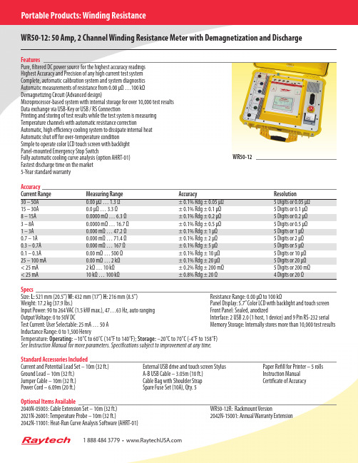
Portable Products: Winding ResistanceWR50-12: 50 Amp, 2 Channel Winding Resistance Meter with Demagnetization and DischargeFeaturesWR50-12Fastest discharge time on the market5-Year standard warrantyAccuracyCurrent Range Measuring Range Accuracy Resolution± 0.1% Rdg ± 0.05 µΩ 5 Digits or 0.05 µΩ0.0 µΩ … 3.3 Ω ± 0.1% Rdg ± 0.1 µΩ 5 Digits or 0.1 µΩ8 – 15A 0.0000 mΩ … 6.3 Ω ± 0.1% Rdg ± 0.2 µΩ 5 Digits or 0.2 µΩ3 – 8A 0.0000 mΩ … 16.7 Ω ± 0.1% Rdg ± 0.5 µΩ 5 Digits or 0.5 µΩ1 – 3A 0.000 mΩ … 47.2 Ω ± 0.1% Rdg ± 1 µΩ 5 Digits or 1 µΩ0.7 – 1A 0.000 mΩ … 71.4 Ω ± 0.1% Rdg ± 2 µΩ 5 Digits or 2 µΩ0.3 – 0.7A 0.000 mΩ … 167 Ω ± 0.1% Rdg ± 5 µΩ 5 Digits or 5 µΩ0.1 – 0.3A 0.00 mΩ … 500 Ω ± 0.1% Rdg ± 10 µΩ 5 Digits or 10 µΩ25 – 100 mA 0.00 mΩ … 2 kΩ ± 0.1% Rdg ± 20 µΩ 5 Digits or 20 µΩ< 25 mA 2 kΩ … 10 kΩ ± 0.2% Rdg ± 200 mΩ 5 Digits or 200 mΩ4 Digits or 20 ΩSpecsSize: L:521 mm (20.5”) W:432 mm (17”) H: 216 mm (8.5”) Resistance Range: 0.00 µΩ to 100 kΩWeight: 17.2 kg (37.9 lbs.) Panel Display: 5.7” Color LCD with backlight and touch screen Input Power: 90 to 264 VAC (1.5 kW max.), 47…63 Hz, auto ranging Front Panel: Sealed, anodizedOutput Voltage: 0 to 50V DC Interface: 2 USB 2.0 (1 host, 1 device) and 9 Pin RS-232 serial Test Current: User Selectable: 25 mA … 50 A Memory Storage: Internally stores more than 10,000 test results Inductance Range: 0 to 1,500 HenryTemperature: Operating:–10°C to 60°C (14°F to 140°F); Storage:–20°C to 70°C (-4°F to 158°F)See Instruction Manual for more parameters. Specifications subject to improvement at any time.Standard Accessories IncludedCurrent and Potential Lead Set – 10m (32 ft.) External USB drive and touch screen Stylus Paper Refill for Printer – 5 rolls Ground Lead – 10m (32 ft.) A-B USB Cable – 3.05m (10 ft.) Instruction ManualJumper Cable – 10m (32 ft.) Cable Bag with Shoulder Strap Certificate of AccuracyPower Cord – 6.09m (20 ft.) Spare Fuse Set (10A), Qty. 5Optional Items Available2040N-05003: Cable Extension Set –10m (32 ft.) WR50-12R: Rackmount Version2021N-26001: Temperature Probe – 10m (32 ft.) 2042N-15001: Annual Warranty Extension2042N-11001: Heat-Run Curve Analysis Software (AHRT-01)188****3779•Raytech is a world leader in the design and production of precision electronicmeasuring instruments and systems. The unique design approach of the engineering team at Raytech has resulted in the development of highly regarded measuring instruments,which have set new standards in the electrical testing industry.Our exceptional reputation for support and service is unmatched.Raytech products are designed for many years of trouble-free use, which is why we can offer a standard 5-year warranty – guaranteeing the highest quality instrumentation available.Raytech USA118 S. 2nd StreetPerkasie, PA 18944Tel: +267 404 2676Email:********************** Raytech GmbH Oberebenestrasse 115620 Bremgarten, Switzerland Tel: +41 56 648 60 10Email:******************www.Raytech.ch。