
纯正弦波逆变器 规格书
3000W 纯正弦波DC-AC逆变器
■特性:
●纯正弦波输出(THD<3%)
●瞬间功率高达6000W
●效率高达90%
●保护各类:电池高低压保护/输出短路保护/过负载保护/
过温度保护/输入反接保护/电池低压警报
●应用:家电,电动工具,办公和便携式设备,车辆和游艇等。
●1年保修
电气规格
型号BEP3000S
输出额定功率(Typ.) 3000W 3000W
交流电压220V 220V
频率50HZ±0.5HZ50HZ±0.5HZ
波形额定电压下, 纯正弦波(THD<3%) 额定电压下, 纯正弦波(THD<3%)
输入电池电压12V 24V
电压范围(Typ.) 10V-15V 20V-30V 直流电流(Typ.) 276A 138A
空载损耗≤3.8A ≤2A
关机模式电流≤10mA ≤10mA 效率(Typ.) ≥90% ≥90% 电池类型铅酸电池铅酸电池
电池输入保护保险片40A*8 20A*8
电池低压警报10.5V±0.5V20V±1V
电池低压保护9.5V±0.5V19V±1V
电池高压保护15.5V±0.5V30V±1V
电池反接保护通过内部保险片通过内部保险片
输出保护过温度
75℃±5℃75℃±5℃
亮红色指示灯,有报警声,无输出亮红色指示灯,有报警声,无输出
输出短路亮红色指示灯,取消短路后自动恢复正常亮红色指示灯,取消短路后自动恢复正常
过负载(Typ.)
≥ 3000W ≥3000W
亮红色指示灯,自锁, 降低负载重启恢复正常输出亮红色指示灯,自锁, 降低负载重启恢复正常输出
USB 输出电压5V
输出电流500mA
环境工作温度0-40℃@100%负载
工作湿度20-90%RH,无冷藏
储存温度、湿度-30℃-+70℃,10-95%RH
其它重量净重:6.02Kg 毛重:7.41Kg 尺寸529**180*142 mm(L*W*H)
包装558*246*209 mm(L*W*H)
备注如未特别说明,所有规格参数25℃环境温度下进行量测。
3000W 纯 正 弦 波DC-AC 逆 变 器
BE P 3000 S
■机构尺寸
单位:mm
公司名称BELTTT 输出瓦数:3000W
纯正弦波逆变器。
2000W正弦波逆变器说明书

★★★设备使用前,请仔细阅读使用说明书正弦波逆变器使用说明书11一、概述我公司生产的纯正弦波逆变器,可将蓄电池的直流电能逆变成额定电压输出的正弦波交流电,供用户负载使用。
本逆变器外观大方、指示直观、操作方便。
具有交流自动稳压输出、过压、欠压、过载、过热、短路、反接等完善的保护功能。
核心控制元件采用美国原装微控制器,功率器件则采用优质的进口器件。
本电源整机效率高,空载损耗底。
经大量实验证明,该系统运行安全、稳定、可靠,使用寿命长。
具有很高的性能价格比。
二、功能简介1、充电控制功能:风力发电机输出的交流电能先转换成直流电能,然后和太阳能电池板一起对蓄电池进行充电。
2、逆变输出功能:在打开前面板的“逆变开关”后,本电源即将蓄电池的直流电转化成额定电压220V的正弦波交流电,并从后面板的交流插座输出。
3、自动稳压功能:当蓄电池组电压在电压欠压点和过压点之间波动,负载在额定功率之内变化时,本机具有交流输出自动稳压功能。
4、过压保护功能:当蓄电池电压大于“过压点”时,设备将自动切断逆变输出,液晶显示“过压”,同时蜂鸣器发出十秒的报警声。
待电压下降到“过压恢复点”时,逆变才自动恢复;5、欠压保护功能:当蓄电池电压低于“欠压点”时,为了避免过放而损坏蓄电池,本设备将自动切断逆变输出。
此时,液晶显示“欠压”,同时蜂鸣器发出十秒的报警声。
待电压上升到“欠压恢复点”时,逆变才自动恢复.6、过载保护功能:当交流输出功率超额定功率时,本设备将自动切断逆变输出,同时,液晶显示“过载”,蜂鸣器发出十秒的报警声。
关闭前面板的“逆变开关”,可使“过载”显示消失。
如需重新开机,则必须检查确认负载功率在允许范围内,然后再打开“逆变开关”恢复逆变输出.7、短路保护功能:如果交流输出回路发生短路,本设备将自动切断逆变输出,同时,液晶闪烁显示“过载”,同时蜂鸣器发出十秒的报警声。
关闭前面板的“逆变开关”,可使“过载”显示消失。
如需重新开机,则必须检查确认输出线路正常后,再打开“逆变开关”,恢复逆变输出.8、过热保护功能:如果机箱内部控制部分的温度过高,本设备将自动切断逆变输出,同时,液晶显示“过热”,同时蜂鸣器发出十秒的报警声。
phocos pswh-5kw-23048v pswh-3kw-23024v 纯正弦波逆变器 使用和
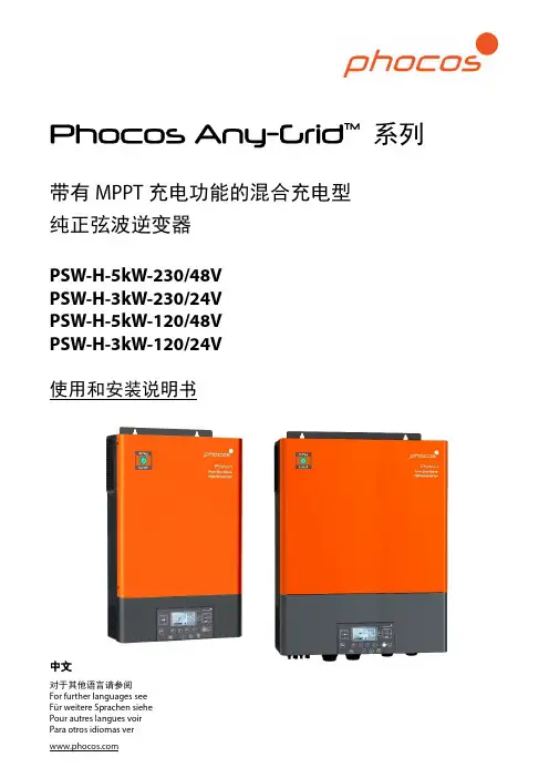
系列带有MPPT充电功能的混合充电型纯正弦波逆变器PSW-H-5kW-230/48VPSW-H-3kW-230/24VPSW-H-5kW-120/48VPSW-H-3kW-120/24V使用和安装说明书中文对于其他语言请参阅For further languages seeFür weitere Sprachen siehe目录1.0产品介绍 (2)2.0重要安全信息 (2)3.0法规信息 (3)4.0概述 (3)功能概述 (3)产品概述 (5)5.0安装 (6)包装清单 (6)电池接线扩展盒和线缆密封管的安装 (6)产品固定安装 (6)电池连接 (7)交流输入电源和交流输出负载的连接 (8)光伏连接 (10)最后的总装 (11)远程显示单元安装 (11)多台单相并联、三相连接或者分相连接 (13)6.0BLE蓝牙连接手机 (19)7.0继电器触点 (19)8.0操作 (19)逆变器供电开关 (19)显示和控制单元 (20)显示图标 (21)设备操作设置 (23)USB和计时器设置 (31)即时数据屏幕视图 (33)操作模式功能描述 (39)9.0失效模式代码 (42)10.0告警代码 (43)11.0故障排除 (45)12.0技术参数 (48)并网 (48)离网 (49)电池充电 (50)通用技术参数 (51)13.0质保 (52)质保条款 (52)免责声明 (52)1.0产品介绍尊敬的客户,感谢您选择Phocos产品。
Any-Grid™混合充电型纯正弦波逆变器系列产品具有众多出色的功能和使用实例,例如:用作纯离网型逆变器,适用于没有公共电网接入的应用。
用作备有太阳能充电(可选)的不间断电源功能(UPS),用于间歇性或不稳定的公共电网。
用作公共电网或交流发电机接入的逆变器,通过优先使用太阳能或电池能源来减少公共电网或交流发电机的使用需求,从而节省电费或燃油。
在合法的情况下,无论是否连接电池,都可能向公共电网馈电。
逆变器产品规格型号标准
产品尺寸(DIMENSIONS L×W×H)
25.5×15.5×6.0CM
机身重量(WEIGHT)
1130g
外壳材质(OUTER SHELL)
铝合金主体+塑胶端盖
包装方式(PACKING)
彩盒
冷却方式(COOLING)
风扇高速风冷(HIGH SPEED COOLING FAN)
Approximately 90%
输出插座(OUTPUT AC OUTLET)
万能通用插座(Universal Socket)
使用环境温度(TEMPERATURE)
ENVIRONMENT TEMPERATURE -20~+40℃
产品尺寸(DIMENSIONS L×W×H)
22.5×15.5×6.0CM
输出电压AC(AC OUTPUT)
220V~240V AC
输出频率(OUTPUT FREQUENCY)
50±2HZ
LCD显示器工作状态
直流输入电压显示和交流输出电压显示以及工作状态故障显示
输出波形(OUTPUT WAVE FORM)
纯正正弦波(Pure Sine Wave)
转换效率(MAX.EFFICIENCY)
使用环境温度(TEMPERATURE)
ENVIRONMENT TEMPERATURE -20~+40℃
产品尺寸(DIMENSIONS L×W×H)
29.0×22.0×9.0CM
机身重量(WEIGHT)
3000g
外壳材质(OUTER SHELL)
铝合金主体+塑胶端盖
包装方式(PACKING)
工频纯正弦波逆变器
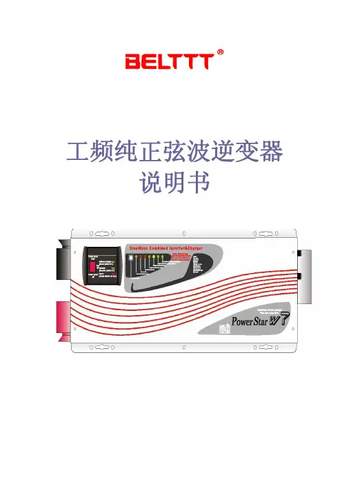
工频纯正弦波逆变器说明书目录目录 (2)一.特点 (3)二.面板说明 (4)三.技术参数 (5)四.安装 (6)1.连接示意图 (6)2.使用导线平方数 (6)3.安装指南 (7)4.远程控制安装 (7)五.蓄电池类型选择 (7)六.工作原理 (9)1.充电阶段解释 (9)2.充电曲线图 (9)七.使用说明 (10)八.应用领域 (10)1.家庭娱乐 (10)2.家庭设备 (10)3.办公设备 (11)4.照明设备 (11)九.状态指示及故障对照表 (11)一. 特点z安静,高效率运作z前面板LED指示灯和可调开关选择器z可选设置铅酸电池,胶体电池,或玻璃纤维隔板(AGM)电池等 z70A自动三阶段充电(大电流充电,吸收,和浮充 )z快速开关(栅板到电池和电池栅板)的备用电源z较低的闲置电流能和发动机一致,在没有负载情况下节约能源. z在极端环境条件下具有持久的寿命z高负载能力可以承担比较大的负载,在过载情况下能稳定处理 z电路板涂层可以保护他们免遭腐蚀及提高使用寿命和可靠性z持久的粉末涂层,耐腐蚀钢底盘,具有防水功能z保护功能:a)过电压和低电压保护b)高温保护c)自动过载保护d)短路保护二. 面板说明正面面板交流输出端面板 市电输入零线 市电输入火线 机器输出地线市电输入地线 机器输出零线 机器输出火线远程指示灯三. 技术参数输入波形 正弦波(实用工具或发电机)标称输入电压 120V 230V低压跳闸 90V ±4% 184V/154V ±4% 低压重启 100V ±4% 194V/164V ±4% 高压跳闸 140V ±4% 253V ±4% 高压重启 135V ±4% 243V ±4% 交流最大输入电压 150V 270V额定输入频率 50Hz/60Hz(自动检测)低频跳闸 47Hz-50Hz, 57Hz-60Hz高频跳闸 55Hz-50Hz, 65Hz-60Hz输出波形 与输入波形相同(旁路模式)过载保护 断路器短路保护 断路器最大旁路电流 30安培/40安培在线转换式转换效率 95%以上在线切换时间 10ms (标准)旁路无电池连接 是旁路最大电流 30安/40安旁路过载电流 35安/45安(报警)逆变器规格/输出输出波形 纯正弦波持续输出功率 1000W 1500W 2000W 3000W 4000W 5000W 6000W 持续输出功率 1000V A 1500V A 2000V A 3000V A 4000V A 5000V A 6000V A 功率因数 0.9-1.0输出电压调节 ±10% rms输出频率 50Hz ±0.3Hz 60Hz ±0.3Hz额定效率 大于88%峰值额定值 3000W 4500W 6000 9000 2000 15000 18000 短路保护 是 , 故障后十秒 接蓄电池端面板 直流输入负极 直流输入正极逆变器规格/输入额定输入电压12V 24V 48V最小启动电压10V 20V 40V电瓶低电压报警10.5V 21V 42V电瓶低电压脱扣10V 20V 40V高压报警16V 32V 64V节电器启用时低于25瓦节电器远程均为开关调节充电器模式规格输入电压范围 95-127V AC 194-243V AC/ 164-243V AC(W) 输出电压根据电池类型充电电流35A/70A启动时电瓶初始电压 0-15.7V,12V (*2,24V; *4, 48V)过充保护关断15.7V, 12V (*2,24V; *4, 48V)电瓶类型决定充电器(恒定电流四阶段)数控渐进充电四步走远程控制/RS232/USB 是,可选尺寸(mm) 1000W/1500W/2000W/3000W: 442*218*179mm4000W/5000W/6000W: 598*218*179 mm 重量: 1000W 1500W 2000W 3000W 4000W 5000W 6000W17kg 18kg 20kg 22kg 35kg 38kg 40kg 四. 安装1.连接示意图2.使用导线平方数充电或逆变电流导线长0-1.5 米导线长1.5-4.0米125-180A 50平方 70平方180-330A 70平方 90平方3.安装指南a)将本品与蓄电池组距离尽量拉近b)保持阴凉,干燥以及良好通风c)本品放置方向无关d)无论从原厂购买1.5米长的导线,或者使用你自己的线,都要按照导线平方数表所指明的粗细以确保对直流电流足够粗。
工频3000W纯正弦波逆变器的参数

苏州日不落能源设备有限公司地址:江苏 苏州 金阊科技产业园A-504
● ●
邮编:215000
电话:+86 512 68638910 传真:+86 512 68638916
SPT3000-112 SPT3000-124 SPT3000-148 SPT3000-212 SPT3000-224 SPT3000-248 3000W 9000W 12VDC 24VDC 100/110/120VAC±5% 50/60Hz±0.5% 0.1~1 83% 86% 88% <10W <10ms 190~245VAC 10.0~16.0VDC 20.0~31.0VDC 42.0~62.0VDC 10.0~16.0VDC 20.0~31.0VDC 42.0~62.0VDC 70A 40A 20A LED红色 UL458 FCC Part15 ClassA -20~40℃ 20~90%RH -30~70℃ 负载控制冷却风扇 24 460*220*190(L*W*H) 车载,游艇,太阳能系统,移动设备,工控,电动工具和家庭办公等 *备注:以上规格参数若有修改,恕不另行通知。 LVD(EN60950) CE (EN55022:2006+A1:2007) 70A 40A 20A 85% 87% 90% 48VDC 12VDC 24VDC 220/230/240VAC±3% 48VDC
参数
型号 输出功率 冲击功率 输入电压 输出电压 输出频率 功率因素 满载效率 待机损耗 切换时间 输入AC电压范围 输入电压范围 DC充电电流 故障指示 安规认证 电磁干扰 工作温度 工作湿度 内储藏温度 冷却 重量(kg) 尺寸(mm) 运用
SPT3000系列
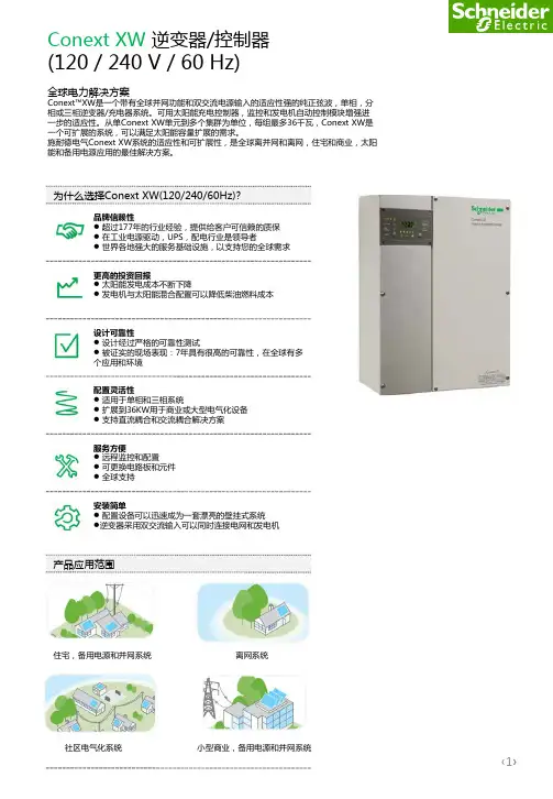
XW-120240-60逆变器规格书
L-L: 75 A (20秒)
L-L: 35 A (20 秒)
L-N: 40 A (20 秒)
纯正弦波
纯正弦波
94.0%
95.6%
<8W
<8W
AC1 (电网侧), AC2 (发电机侧)
120/240 Vac 分相
60 A 两极式
是
是
91.0%
93.0%
4000 W
4500 W
XW6048-120/240-60 6.0kVA 12.0kVA(15秒) L-N: 105 A (15 秒) L-L: 52.5 A (15 秒) 纯正弦波 95.4% <8W
为什么选择Conext XW(120/240/60Hz)?
品牌信赖性 超过177年的行业经验,提供给客户可信赖的质保 在工业电源驱动,UPS,配电行业是领导者 世界各地强大的服务基础设施,以支持您的全球需求
更高的投资回报 太阳能发电成本不断下降 发电机与太阳能混合配置可以降低柴油燃料成本
150 A
85 A
100 A
85.80%
90.20%
89.40%
0.98
0.98
0.98
单相:最大可并联4组(24kW);三相:每相最大2组,总共6组(36kW)
0-12 Vdc, 最大250 mA DC
是
是
是
Xanbus™ (发布-订阅网络,无需网络集线器或专门的通讯卡)
壁挂型,包含护板
23 x 16 x 9” (580 x 410 x 230 mm)
显示面板
蓄电池温度传感器 质保期 部件编号 环境参数 箱体类型 运行温度范围 配件 远程显示
发电机支持
纯正弦波逆变器驱动板说明书
ELECTRONIC GIANT EGS001 用户手册纯正弦波逆变器驱动板EG8010 芯片测试板EGS001正弦波逆变器驱动板用户手册V1.2版本更新:V1.1:针脚定义中,将1HO、1LO和VS1的定义更改为右桥臂,将2HO、2LO和VS2的定义更改为左桥臂。
V1.2:更新原理图中短路保护电路。
1. 描述EGS001是一款专门用于单相纯正弦波逆变器的驱动板。
采用单相纯正弦波逆变器专用芯片EG8010为控制芯片,驱动芯片采用IR2110S。
驱动板上集成了电压、电流、温度保护功能,LED告警显示功能及风扇控制功能,并可通过跳线设置50/60Hz输出,软启动功能及死区大小。
EG8010是一款数字化的、功能很完善的自带死区控制的纯正弦波逆变发生器芯片,应用于DC-DC-AC两级功率变换架构或DC-AC单级工频变压器升压变换架构,外接12MHz晶体振荡器,能实现高精度、失真和谐波都很小的纯正弦波50Hz或60Hz逆变器专用芯片。
该芯片采用CMOS工艺,内部集成SPWM正弦发生器、死区时间控制电路、幅度因子乘法器、软启动电路、保护电路、RS232串行通讯接口和12832串行液晶驱动模块等功能。
2. 电路原理图EGS001驱动板原理图220V输出220V输出图2‐1. EGS001纯正弦波逆变器驱动板电路原理图3. 针脚及跳线3.1 EGS001正视图图3‐1. EGS001驱动板针脚定义3.2 针脚描述针脚序号针脚名称I/O描述1 IFB I 输出电流反馈输入端,引脚输入电压大于0.5V 时过流保护2 GND GND 接地端3 1LO O 右桥臂下管驱动门极输出4 GND GND 接地端5 VS1 O 右桥臂上下功率MOS 管中心点输出6 1HO O 右桥臂上管驱动门极输出7 GND GND 接地端8 2LO O 左桥臂下管驱动门极输出 9 VS2 O 左桥臂上下功率MOS 管中心点输出 10 2HO O 左桥臂上管驱动门极输出 11 GND GND 接地端12 +12V +12V +12V 电源电压输入,输入电压范围: 10V~15V 13 GND GND接地端 14 +5V +5V +5V 电源电压输入15 VFB I 输出电压反馈输入端,具体功能及电路请参照EG8010芯片手册17. FANCTR16. TFB15. VFB14. +5V13. GND12. +12V11. GND10. 2HO9. VS28. 2LO7. GND6. 1HO5. VS14. GND3. 1LO2. GND1. IFB16 TFB I 温度反馈输入端,引脚输入电压大于4.3V 时过热保护17 FANCTR O外接风扇控制,当T FB 引脚检测到温度高于45℃时,输出高电平“1”使风扇运行,运行后温度低于40℃时,输出低电平“0”使风扇停止工作3.3 跳线设置序号跳线名称标号设置说明JP1当JP1短路时,选择60Hz 输出 1 FRQSEL0JP5 当JP5短路时,选择50Hz 输出 JP2当JP2短路时,使能3秒软启动功能 2 SSTJP6 当JP6短路时,关闭软启动功能JP33 DT0JP7 JP44 DT1JP8当JP7和JP8同时短路时:死区时间为300ns 当JP3和JP8同时短路时:死区时间为500ns 当JP4和JP7同时短路时:死区时间为1.0us 当JP3和JP4同时短路时:死区时间为1.5us出厂时驱动板跳线默认设置为JP5、JP2、JP7、JP8短路,对应功能为50Hz 、3S 软启动、死区时间300nS ,用户可根据自己需求更改。
英普纯正正弦波逆变器(12V 24V 48V)用户手册说明书
POWER INVERTERRoHSPromote green energyModified Sine Wave Pure Sine WaveUSERUSER MANUALStatement: there are some differences between the image and the real object, please subject to real objects; Products are being updated constantly,if you need to learn more,Do not open inverter without permission!Universal Australia France&Germany I talySmall Europe Type South Africa UK USAAustralia Europe&USA&Japan France Germany60006000W12000W12/24/48VPure sine wave or Modified sine waveThank you for purchasing our Power Inverter.lt is a compact and highly portable power inverter Which has an excellent track record in the field of high frequency inverter. From the 12V/24V/48V DC outlet in your vehicle or boat, or directly from a dedicated 12V/24V/48V DC battery,this inverter can efficiently and reliably power a wide variety of house hold AC products,such as TV, Computers,Air-conditioner etc. Please read this guide before installing or using the Due to our continuous work to upgrade and improve our products, we may change or revise the contents of this manual instructions or any part of it without giving any further notice.Pure sine wave or Modified sine wave600W 1200W800800W 1600W12/24/48V 12/24/48VType:TypeA,TypeB,TypeC,TypeD,TypeE,TypeF,TypeG;75W,100W,150W,200W,300W,500W,600W,800W,1000W,1200W,1500W,2000W,2500W,3000W,4000W,5000W,6000W,8000W,10000W,1205,2405,1210,2410,1215,2415,1220,2420,1230,2430,1250,2450,M:Modified sine wave inverterSY:Movable solar power system;Pure sine wave or Modified sine wave25002500W 5000W30003000W 6000W12/24/48V 12/24/48V………………………………………………………………………………………………………………………………………………………………………………………………………………………………………………………………………………………………………………………………………………………………………………………………………………………………………………………………………………………………………………………………………………………………………………………………………………………………………………………………………………………………………………………………………………………………………………………………………………………………………………………………………12-3456677-889-1011-151617-2122-24SOLUTIONShorten the wire or use widercable. Charge the battery.Make the inverter get cooler.Improve ventilation around the inverter. Place the inverter at a cool place.Feed the load according to e bigger power Check the connection and ower a s a n ormal h ousehold f an o r v ent o penings. 1-4. Do not under any circumstance, connect the inverter to AC power.1-5. The inverter housing may become uncomfortably warm, reaching 140F(60℃)under extended high power opeartion. Ensure at least 2 inches (5cm) of air space is maintained on all sides of the inverter.During operation, keep away from materials that 1-6. Do not use the inverter in the presence of flammable fumes or gases, such as in the bilge of a gasoline powered boat,or near a propane tanks. Do not use the inverter inSOLUTIONmodified sine wave real effective value to get the accurate Charge the battery or change batteryan enclosure containing automotive-type, lead-acid batteries.These batteries, unlike sealed batteries,emit explosive hy-drogenation which can be ignited by sparks from electrical tlets.T h e in verter w ill be 1-8. Do not expose the inverter to temperatures exceeding 104F(40℃).CAUTION! Do not use the inverter with the following equipment;1-9. Small battery operated products such as rechargeable falshlights,some rechargeabl shavers, and nightlights that are plugged directly into an AC receptacle to recharge.1-10. Certain battery chargers for battery packs used in hand powered tools. These chargers will have warning labels stating that dangerous voltages are present at the 1-11. Note DC voltage of battery should be similar to input DC voltage of power inverter (for example DC12V of battery should be connected with input voltage 12V of the inverter).SOLUTIONUse appliances havingpower below the inverter ′s Since the peak power of the electric appliances exceeds the peak power of the inverter, use an appliance with a peak power consistant with the inverterThe electric appliances does not work,and the red FAULT indicator of the inverter lights.The inverter come in two types; pure sine wave power type and modified sine wave type. In the pure sine wave power inverter, the 240V AC output harmonically follows a smooth sine wave and is almost identical to normal mains electricity. As a result, the pure sine wave output would be A Graphic Comparison of Modified Sine Wave and Pure Sine Wave is shown belew:Pure Sine WaveOverload protection / Over voltage protection / Short Circuit protection / Over、Sand bl a st M achine、Scanning Machine etc.Lamp or LED、SewingFreezer、 Coffemaker、For safe and optimum performance,install the inverter in a location that is:3-1-2. Cool - Operate only in ambient temperatures between 32F (0℃) and 104F ). Keep away from heating vents or other heat producing equipment.3-1-3. Safe - Do not install inverter in a compartment with batteries or flammable 3-1-4. Well ventilated - Allow at least 2 inches(5cm)clearance above and on all sides 3-1-5. Clean and free of dust and dirt- This is especially important if the inverterSOLUTIONReplace the battery or usebattery charger to charge yourSwitch off the inverter and let itget cooled for 15 minutes. Clearobjectes around the fan and theinverter. Place the inverter at acool place.Reduce loadaccording to requirements.Check the working state of thecharging system. Make sure theoutput voltage of the battery iswithin the proper voltageAC appliances do not work, and the green power indicator does not light.SOLUTIONCheck the battery, replace it ifcorrect the connection to battery,the inverter may be damaged.Replace the fuse inside inverter(outside warranty cover)Check the cables and theconnection, screw tight thewiring terminal-14-The Sketch of InverterModified sine wave800W-2000W,Pure sine wave800W-2000WOutputs connectionTips :48V a nd 2 4V i n verters a re c onnected i n s imilar w ays,b ut t h e b atteries i n s eries.AC OutletsGround Connection nutUSB DC 5VBattery Connection Red+Battery Connection Black-Battery connecting cablesFanThe inverter works in two stages. During the first stage, the DC to DC converter increases the DC input voltage from the power source (eg.A 12V battery) to 300V DC In the second stage, the high voltage DC is converted to the watts you need (AC) using advanced power MOSFET tran-sistors or IGBT technology in a full bridge configuration The result is excellent overload capability and the capacity to operate difficult reactive loads 3-3-1.Attach the ring type connector marked with redto the positive (+) DC terminal on the inverter and attach the ring connector marked with black to the negative (-) DC A reverse polarity connection (positive to negative) may damage the inverter (Fuse)Damage caused by a reverse polarity connection would probably invalidate your warrantyWARNING: Sparking may occur when connecting the unit to the battery, makesure no flammable fumes are present before making any connections.3-5-1. When a 12V/24V/48V DC outlet or battery properly connected to the inverter,turn on the ON/OFF, the green Power indicator will light, and it deliver AC power to the 3-5-2. Plug the AC appliances you wish to operated into the AC outlet (s) and switch NOTICE: When connect to the appliances,remember to turn on the inverter 3-5-3. If the audible alarm be ignored the inverter may be automatically shut down when the battery voltage drops to 9.8-10.2V / 19.6-20.4V / 39.2-40.8V. in order to 3-5-4. If the AC appliances rated power is higher than inverters rating(or the appliance draws excessive surge power),the inverter will shut down. The red FAULT indicator will light. 3-5.5. If the inverter exceeds a safe operating temperature, due to insufficient.ventilation or a high surrounding temperature , it will automatically shut down. The red FAULT indicator will light and the audio warning alarm will sound.3-3-2. Tighten the nut on each DC terminal by hand until it is snug. If the power more 3-3-3. When the inverter is not in use , unplug it from the 12V/ 24V /48V DC 3-5-6. If a defective battery charge system has caused the battery voltage to rise to a dangerously high level, the inverter will automatically shut down.3-5-7. The cooling fan is designed to operate only when the temperature goes up or CAUTION: Before using the inverter,please provide a ground connection wire. On the rear panel of the inverter is at erminal fitted with a nut for connecting to the inverter and to the earth terminal of the AC output socket. Please choose heavy duty, insulated green/yellow wire. Drive into the ground to a depth of 1-2m or more. In a vehicle,connect the inverter to the chassis of the vehicle. In a boat, connect to the boat ˋs We advise that please use deep cycle battery. If you hear the low voltage alarm, please stop the inverter immediately. When the battery is fully charged, the inverter can be used again. If you use the inverter in a car, then it would be necessary to run the engine of your car after each time you use the inverter. You can run the engine for 10 minutes or so to recharge the -13-Modified sine wave3000W-6000W,Pure sine wave3000W-6000WLight Indicators Power (Green) and Fault (Red)Ground Connection nutFanBattery Connectiong LinesUSB DC 5VON/OFF SwitchAC OutletsBattery Connection,Red+, Black-CAUTION: Although the inverter incorporates the protection function against over-voltage, there would be still the possibility of getting the unit damaged Modified sine wave150W-600W,Pure sine wave150W-600WCrocodile Clip linesUSB DC 5VON/OFFSwitchAC OutletsCigarette Lighter FanBattery Connection,Red+, Black-。
TPower系列纯正弦波逆变器用户手册说明书
Pure Sine Wave InverterUser ManualTP10K/TP10KBContentsImportant Safety Instructions (1)1. Product Overview (5)1.1 Information & Features (5)1.2 Structure (6)1.3 Name definition (9)1.4 Connection schematic diagram (9)1.5 Electrical schematic diagram (10)2. Installation (11)2.1 Warning (11)2.2 Wire & breaker selection (11)2.3 Instructions (12)2.4 Output voltage/frequency grade switch (17)3. Interface (18)3.1 Indicator (18)3.2 Buzzer (19)3.3 Buttons (19)3.3 LCD Display (19)3.4 Icon (20)3.5 Operation (20)4. Protection (22)5. Troubleshooting (25)6. Maintenance (27)7. Specifications (28)AnnexⅠ Disclaimer (32)AnnexⅡ Mechanical Dimension Diagram (33)Important Safety InstructionsPlease reserve this manual for future review.This manual contains all the instructions about safety, installation, and operation for TPower series pure sine wave inverter (hereinafter referred to as the inverter).Explanation of symbolsTo enable the user to use the product efficiently, as well as to ensure personal and property safety, this manual provides related information and emphasize the following symbols.Please read the related words carefully when you encounter the following symbols in the manual.TIP:Indicates any practical advice for reference.IMPORTANT:Indicates a critical tip during the operation, if ignored, may cause the device to run in error.CAUTION:Indicates potential hazards, if not avoided, may cause the device damaged.WARNING:Indicates the danger of electric shock, if not avoided, would cause casualties.WARNING HOT SURFACE:Indicates the risk of high temperature, if not avoided, would cause scalds.Read the user manual carefully before any operation.Symbols of inverterWARNING: The entire system should be installed by professional and technical personnel.2. Requirements for professional and technical personnel:•Professionally trained;•Familiar with related safety specification for the electrical system;•Read this manual carefully, and master related safety cautions.3. Professional and technical personnel is allowed to do:•Install the inverter to the specified location;•Conduct trial operations for the inverter;•Operate and maintain the inverter.4. Safety cautions before installation:IMPORTANT: When receiving the inverter, please firstly check if there is any damage occurred in transportation, if find any problem, please contact the transportation company or our company in time.CAUTION: When place or move the inverter, must follow the instructions in the manual.CAUTION: When install the inverter, must evaluate whether the operation area exists any arc danger.WARNING: Do not place the inverter in places where children can touch.WARNING: The inverter is off-grid type, and it is strictly prohibited to be connected to the grid; otherwise the inverter would be damaged.WARNING: The inverter is only allowed for stand-alone operation, and it is prohibited to connect multiple units’ output in p arallel or in series; otherwise the inverter would be damaged.5. Safety cautions for mechanical installation:WARNING: Before installation, must make sure the inverter has no electrical connection.WARNING: Ensure the heat dissipation space for the inverter installation, and do not install the inverter in humid, greasy, flammable, explosive, dust accumulative or other severe environments.6. Safety cautions for electrical connection:CAUTION: Check if all the wiring connections are tight, to avoid the danger of heat accumulation due to a loose connection.WARNING: Both utility input and AC output are of high voltage, do not touch the wiring connection to avoid electric shock.7. Safety cautions for inverter operation:WARNING HOT SURFACE: When the inverter is working, its heat sink and casing will generate a lot of heat, the temperature would be very high, please do not touch it.CAUTION: When the inverter is working, please do not open the inverter cabinet to operate.8. The dangerous operations which would cause electric arc, fire or explosion: •Hot plug the high voltage fuse on the inverter DC side.•Touch the wire end which hasn’t been insulation treated and maybe electriferous.•Touch the wiring copper row, terminals or internal devices which may be electriferous.•Power cable connection is loose.•Screw or other spare parts inadvertently falls into the inverter.•Incorrect operation by untrained non-professional or technical personnel.WARNING: Once an accident occurs, must be handled by professional and technical personnel. Any incorrect operation would cause a more severe accident.9. Safety cautions for stopping the inverter:•Firstly turn off the breakers on the utility input side and AC output side, then turn off the DC switch;•After the inverter stop working for five minutes, the internal conductive devices could be touched;•The inverter can be restarted after removing the faults which may affect its safety performance;•No maintenance parts in the inverter, if any maintenance service is required, please contact our after-sales service personnel.10. Safety cautions for inverter maintenance:•Testing equipment is recommended to check the inverter, to make sure there is no voltage or current;•When conducting electrical connection and maintenance work, must post temporary warning sign or put up barriers, to prevent unrelated personnel from entering the electrical connection or maintenance area;•Improper maintenance operation to the inverter may cause personal injury or equipment damage;•To prevent electrostatic damage, recommend to ware antistatic wrist strap or avoid unnecessary contact with the circuit board.CAUTION: The safety mark, warning label and nameplate on the inverter should be clearly visible, not removed or covered.1.Product Overview1.1Information & FeaturesTPower series is designed aspure sine wave power frequency inverter, whichconverts 110/220VDC to220/230VAC.Thisdevice consists of a DC-AC inverting module and AC-AC bypass module in parallel, also featuredwithhigh reliability, high efficiency, concise appearance, full protection, easy installation and operationfunctions.DC-AC inverting module is anintelligent and full digital designed component with advanced SPWM technology. The module is designed with the pure sine wave output toconvert 110/220VDC to220/230VAC for multiple types of AC loads, such as home appliances, electric tools, industrial devices, audio equipment and solar photovoltaic system.AC-AC bypass module used advanced control algorithm to ensure the stability of output voltage and achieve the fast switching feature. Also the high reliability and high-performance semiconductor inside the module reduce the size and prolong the service life.The 4.2 inches segment type of LCD displays the system operation data and statesin real time.The case in sheet-metal design is featured with high intensity and shielding electromagnetic interference. Also, the universal rotary caster is optional for the system, which contains lifting support feet to fix or move the inverter at anytime and improve product mobility and flexibility.Features:•Advanced SPWM technology and pure sine wave output•Fully digitalized voltage and current double closed-loop control•Low output harmonic distortion(THD≤3%)•Mode selection of bypass priority and inverter priority•Output voltage 220/230VAC and frequency 50/60Hz selectable•Real-time power queryand output power statistics function•Automatic protection featuresof the short circuit, overheating and overload.• 4.2 inches LCD display the system operation data and state dynamically with friendly AI interface•Multiple LED indicators show the operating status of the system in real-time •Designed with soft boot control to avoid the battery be damaged by high current impact when turning on the system•AC OUT button controls the AC output individually•Smart fan control reduces energy consumption and noise•Use popular semiconductor modules with high reliability and low power consumption•Designed with remote switch & RS485 communication interface to achieve the features of remote monitoring and hardware Stop&Start, also the Wi-Fi and Bluetooth communication modules are selectable•Universal rotary caster is optional for free movement and fixation.•Modular design, easy maintenance and repair1.2 Structure(1) FOOT MASTER caster(Optional accessory)Rotate clockwise to raise the supporting feet, then tomove the inverter.Rotate counterclockwise to lower the supporting feet,then to fix the inverter.⑵Terminals and breakers★Interface connection method :(3)DC fan and AC fanDC fan 2 pieces:When the radiator temperature rises to 45℃ above, the DC fans will start; when the radiator temperature declines to 35℃ below, the DC fans will stop .IMPORTANT: DC fans have the self-checking function when the inverter is powered on, the DC fans would run for three seconds automatically.AC fan 3 pieces:Inverter priority:When the internal temperature rises to 35℃ above, and with inverter output, the AC fans will start.When internal temperature declines to 30℃ below, or with no inverter output, the AC fans will stop.1.3Name definition1.4Connection schematic diagramWARNING: The AC equipment must be determined according to the output power of the inverter. Do not connect the load in excess of the inverter’s maximum input power, otherwise, the inverter may be damaged.2. Installation2.1 Warning•Please read the manual carefully to get familiar with the installation steps before installation.•Be very careful when installing the batteries, especially flooded lead-acid battery.Please wear eye protection, and have fresh water available to rinse if any contact with battery acid.•Keep the battery away from any metal objects, which may cause a short circuit of the battery.•Loose connections and corroded wires may result in high heat that can melt wire insulation, burn surrounding materials, or even cause a fire. Ensure tight connections and use cable clamps to secure cables and prevent them from swaying in motion.•Select the system connection cables according to the current density no higher than 5A/mm2.(In accordance with the National Electrical Code Article 690, NFPA70).•For outdoor installation, keep out of the direct sunshine and rain infiltration.•High voltage still exists inside the inverter after turning off the switch, do not open or touch the internal devices, wait five minutes before conducting related operations.•Please do not install the inverter in humid, greasy, flammable, explosive, dust accumulative or other severe environments.•Prohibit reverse connection at the battery input end; otherwise it will easily damage the equipment or cause unpredictable danger.•Both utility input and AC output are of high voltage;please do not touch the wiring connection.• When the fan is working, please do not touch it to avoid injury.2.2 Wire& breaker selectionWiring and installation mode should comply with national and local electrical code requirements.••TP30KBIMPORTANT: The wire size is for reference only, use thicker wires to lower the voltage drop and improve the system performance when the distance between utility and inverter or between inverter and batter is far.IMPORTANT: The above wire size and circuit breaker size are for recommendation only, please choose suitable wire and circuit breaker according to the practical situation.2.3InstructionsInstallation steps:Step1:Professional personnel read this manual carefully.Step2:Determine the installation location and heat dissipation space.Move the equipment: as the equipment is relatively large, it is recommended to use forklift or crane; if the ground is flat, it can be moved by wheels.Place to the location: As the equipment is heavy, it is recommended to be placed on flat ground, with 300mm space reserved all around, to ensure heat dissipation.Fix the equipment: If choose the optional caster, rotate counterclockwise to fix and rotate clockwise to move.WARNING: Risk of explosion!Never install the inverter with flooded batteries in a sealed enclosure! Do not install the device in a confined area where battery gas can accumulate.Step3:Take down the junction box cover plate with special tools.Step4:WiringWiring order:❶Ground——❷Battery——❸Utility——❹AC loadsWARNING: Never connect the utility to the inverter output; otherwise the inverter may be damaged.•GroundingThe voltage of the whole system exceeds the safety voltage level. Thus reliable grounding is needed. The grounding wire shall be the thicker wire(no less than 35mm2), and shall be as short as possible. The grounding point shall be as close as possible to the inverter.CAUTION: When wiring, follow the order ❶❷❸❹ to connect the cables to the equipment, then follow the order ❶❷❸❹ to connect ground, battery, utility and load.WARNING: Make sure all the wiring connections are reliable, otherwise massive heat would accumulate at the connection points to damage the terminals, or even cause a fire.WARNING: Danger, high voltage! Utility input, AC output and DC input will produce high voltage, do not close the breakers during wiring, and make sure the correct polarity of each component.Step5:Connect accessories•Mobile APP(For Android only)Download software:—EPEVER(TP)Communication cable: M12-6-male pin + crystal head-1000mm-v1.0Modules: eBox-WIFI-01 and eBox-BLE-01•PC SoftwareDownload software:—Inverter Monitor(TP)Communication cable: 1.M12-6-male pin + crystal head-1000mm-v1.02.RJ45 Coupler3. CC-USB-RS485-0.3mm2-3m-V1.1Step6:Double check the reliability of wiring connections.Step7:Put on the cover plate.Indicator:Inverter indicator on solidLCD:Step8:Close the bypass circuit breakerThe indicator:utility indicator on solidLCD:Step9:Close the load circuit breakerLCD:Step10:Inverter outputMethod 1: Press the “AC output” button for 3 seconds, the inverter would start the output.Method 2: Connect the remote switch, short-circuit the cable 1(red) and cable 2(white) of the remote switch and RS485 communication interface, the inverter would start the output.Indicator:Inverter indicator slowly flashing and load indicator on solid.LCD:Step11:Turn on the loadLED indicators: Inverter and load indicators are slowly flashing.CAUTION: In case the power is supplied to the different AC loads, it is suggested to turn on the loads with larger surge current first, till the load working well, then turn on the loads with smaller surge current. Especially for inductive loads, should be turned on one by one. Do not turn on the loads at the same time, so as not to cause excessive impact to the inverter, to shorten its life span.CAUTION: In case the inverter is not in regular operation, or LCD or indicator displays abnormal, refer to Section 5 to clear the fault or contact the after-sale service personnel of our company.Step12:Power off the equipmentOpen the AC load circuit breaker—long press “AC output” button to turn off the inverter output—open the bypass circuit breaker—open the battery circuit breaker.WARNING: As electricity exists in the capacitance, the LCD screen would be off after 30 seconds; wait 5 minutes before opening the equipment to repair.WARNING: After the inverter is disconnected from utility and battery bank, need to wait 5 minutes before touching the internal conductive devices.WARNING: As the inverter has soft stat design and only takes effect when the first time it starts, do not frequently switch the input circuit breaker when the inverter is incompletely powered off, otherwise the input battery would undergo high current impact. That is, the input circuit breaker can be closed again after the LCD screen is off.2.4Output voltage/frequency grade switchWhen the dial switch 1 is placed to the ON side, the outputfrequency is 60Hz, otherwise it is 50Hz,When the dial switch 2 is placed to the ON side, the outputvoltage is 230VAC, otherwise it is 220VAC.Operating steps:Open the cover plate on the inverter right side, find the dial switches on the control board which is located on the top left corner, see above picture. Set the outputvoltage/frequency according to demand, then restart the inverter to take effect.IMPORTANT: The factory default output voltage is 220VAC, the output frequency is 50Hz.IMPORTANT: The accessories can refer to the Packing list.3. Interface3.1Indicator3.2 Buzzer3.3 Buttons3.3LCDDisplay3.4 IconIcon Icon3.5 Operation1) Turn on the load:Operation:P ress the “AC output” button for 3seconds, load indicator changes from off to solid on.•Switch from inverter mode to bypass modeOperation:P ress “inverter/bypass” button for 3seconds, bypass indicator changes from off to solid on, inverter indicator changes from on solid to off.3)Clear electricity modeOperation:P ress“inverter/bypass” and “browse” button for 3seconds together to clear the accumulated consumed electricity.•Clear faultOperation:Under failure state, short press any button, the buzzer would stop sounding, but the failure code would still be displayed.IMPORTANT: In case of a non-recoverable failure state, if confirmed the fault is cleared, long press “browser” and “AC output” buttons together to clear the fault, the inverter would recover the output.Press the “Browse + AC output” buttons to clear the faults, the inverter recover output.6.MaintenanceThe following inspections and maintenance tasks are recommended at least two times per year for the best performance.•Make sure no block on air-flow around the inverter. Clear up any dirt and fragments on the radiator.•Check all the naked wires to make sure insulation is not damaged for serious solarization. Frictional wear, dryness, insects or rats, etc. Repair or replacesome wires if necessary.•Check and confirm that indicator and display is consistent with required. Pay attention to any troubleshooting or error indication .Take corrective action ifnecessary.•Confirm that all the terminals have no corrosion, insulation damaged, high temperature or burnt/discolored sign, tighten terminal screws to the suggested torque.•Check for dirt, nesting insects and corrosion. If so, clear up in time.•Check and confirm that lightning arrester is in good condition. Replace a new one in time to avoid damaging the inverter/charger and even other equipment.WARNING:Risk of electric shock!Risk of electric shock! Before the above operations, make sure that all the power is turned off, and the electricity in the capacitances is completely discharged, then follow the corresponding inspections and operations.★Instruction for inverter derating1. Temperature derating:When the temperature is over 45℃(113℉), the output power shouldbe reduced by 1KW (Kilowatts) for each 1℃ (Celsius) increase•TP10K,TP10KB•TP20K,TP20KB•TP30K,TP30KB302.Altitude derating:When the altitude is over 1500m, the output power should be reduced by 1KW (Kilowatts) for each 500m (Meter) increase•TP10K,TP10KB•TP20K,TP20KB•TP30K,TP30KB31Mechanical ParametersAnnexⅠDisclaimerThis warranty does not apply under the following conditions:•Damage from improper use or use in an unsuitable environment.•Load or utility current, voltage or power exceeds the rated value of the inverter. •Damage caused by the ambient temperature exceeds the limit working environment temperature.•The accident caused by disobeying the marks or manuals of the inverter, such as electric arc, fire and explosion.•User disassembly or attempted to repair the inverter without permission. •Damage caused by force majeure.•Damage caused during transportation orloading/unloading.32AnnexⅡ Mechanical Dimension Diagram 1.TP10K,TP10KB332.TP20K/TP20KB343.TP30K/TP30KBAny changes without prior notice! Version number: V1.135HUIZHOU EPEVER TECHNOLOGY CO., LTD. Beijing Tel: +86-10-82894896/82894112 Huizhou Tel: +86-752-3889706E-mail:******************Website: 。
48V1500W正弦波逆变器说明书-全功能版
48V/1500W正弦波逆变器一体机说明书Sine wave all-in-one inverter specification 一、概述Introduction本逆变器使用本公司专为逆变器研发的纯正正弦波芯片,具有非常完善的保护功能(包括过载保护,过流保护,高温保护,短路保护,电池高、低压保护)和机器运行LCD状态指示功能。
采用优质的元器件,保证产品高质量,高性能。
本机的输出波形为纯正正弦波,可以适用于任何负载,具备:过流保护,短路保护,过压和欠压保护并且在发生保护后,都可以自动重启恢复输出,本机的体积小巧,便于携带,附带市电切换功能(Bypass)和MPPT光伏充电,是一款性能与功能最完美结合的产品。
功能特性简介:板载元件大部分采用SMD工艺焊接,具有非常高的一次成型率。
功率元件采用坚固耐冲击的平面工艺功率MOSFET,大大降低了大功率负载时候的损耗,提供高冲击功率输出。
采用高抗冲击性设计,保证在冰箱、空调、水泵等强冲击性负载下不会损坏机器。
采用高效率SPWM调制电路,实现最佳的效率与THD值的完美平衡。
采用MPPT充电,最大限度的获取太阳能输出功率并且智能的为电池充电。
内置短路保护,抗冲击保护。
横向散热风道设计,利于散热器风扇端部安装散热。
输入输出采用全隔离设计,隔离电压超过1KV。
极低的空载电流消耗。
极低的传导辐射干扰,完善的EMC电路,通过FCC CLASS B级认证,在敏感的设备上不会造成高频干扰,是这种机器的一大特点。
板载温度传感器,温控风扇开启与关闭。
工作状态指示采用高对比度,大视野LCD显示,所有工作参数一目了然。
蜂鸣器报警指示(可选)。
带有市电切换Bypass功能。
二、使用方法将足够功率的输入电源接上逆变器的输入端子,注意电源电压要在规定范围内,连接的电源线要有足够的承载电流能力,并且尽量短,打开逆变器的电源开关,输出负载在开机前或开机后接入均可。
三、输入电源要求输入电源电压必须在逆变器规定的电压范围内。