saber_corenl磁芯使用手册
S l a rc Metal Halide Arc Lamp操作及安装指南说明书

OPERATIONand INSTALLATIONMANUAL18,21&24S l a rcLamp Products WATT1.Description:S l a rc arc lamp is a high intensity metal halide light source.The light is emitted from an arc discharge between two closely spaced electrodes hermetically sealed inside a small quartz glass tubular envelope.Refer to lamp data sheets and section11of this manual for arc lamp specifications. The light emitted from this arc tube is intense and appropriate safety precautions relating to exposure protection are required.Refer to Figure3of this manual for arc lamp spectral distribution.Metal halide lamps operate at very high temperatures and pressures.The quartz glass must be kept clean. The glass lamps should be handled with care giving special attention of the quartz arc tube.Proper mounting,cooling,and ventilation is required to assure reliable operation of metal halide lamps.Metal halide lamps use high voltage,short duration pulses to initiate operation.The S l a rc is a DClamp and proper electrical wiring polarity must be observed to prevent damage to the lamp.2.PhotobiologicalSafety Compliance Standard RP-27.3: CAUTION:Ultraviolet,visible,and infrared radiation is emitted from metal halide lamps.Possible skin or eye irritation can result from exposures e appropriate shielding.Do not stare at exposed lamp in operation.During operation,the lamp should be enclosed in a housing to prevent injury.Do not remove lamp from equipment until it has cooled.Never handlethe lampwhen it is operating!3.Handling:Protect the quartz arc tube when handling the lamp.The arc tube may be protruding from the end of some reflectorized lamp assemblies.Keep the arc lamp clean.Do not touch the quartz tube,the inside surface of the reflector,and the connectingwires.Contamination can degrade lamp performance or cause premature failures.If necessary,clean the lamp by wiping with a lint free towel or swab immersed in denatured alcohol.Ballast products are electrostatic sensitive electronic assemblies and should be handled as such.Proper Electro-Static Discharge(ESD)handling procedures should be employed.4.Cooling:To ensure proper arc lamp operation and acceptable life,appropriate forced air cooling should be provided when housed in an enclosure.Cooling must beo C sufficient to maintain the temperature at the tip of the arc tube between200 and285o C.Care must also be taken not to overcool the lamp.This will result an arc that is bluer in color and may cause some flicker.The ballast should reside in a well ventilated housing.Forced air cooling is highly recommended,but not a strict requirement.Q401FET heat sink (largest heat sink on PC board)locatedadjacentto the input powero C.See Figures1or2for Q401 connectionsmust be maintainedbelow90FET location.For an optimumtemperaturemeasurementlocation, position and adherea thermocoupleon the reverse side of the Q401heat sink at the same height as the FET.5.Mounting:S l a rc arc lamps are specified for operation in a specific orientation,such as horizontal or vertical base down.Verify specified orientation with the appropriate lamp data mps specified for horizontal operation have a preferred rotational orientation.Refer to the specific lamp data sheet or follow the designation T H IS SIDE UP marked on the lamp base.To prevent damage during lamp installation,mounting,and replacements,care must be taken to avoid mechanical interference with the quartz arc tube. Mount the ballast as desired using the4corner through holes provided on the circuit board assembly or some other acceptable means.See Figure1for mounting hole locations and dimensions.Handling and mounting care should be exercised to prevent mechanical stressing of the prone components on the through hole side of this assembly.6.Ballast Wiring:Inherently,the ballast provides a series of high voltage pulses during lamp starting.To avoid electric shock and arcing,implement appropriate isolation techniques from equipment directly adjacent to the lamp and ballast.As an example,under normal relative humidity conditions,an air gap of9.53mm (0.375)is recommended if no additional isolation techniques are employed.6.1Input Wiring Instructions:Construct an input power connector assembly compatible with the input connector(Molex41761connector2-pin series or equivalent)located on the ballast circuit board assembly.The physical location of the input connector can be found at the bottom edge of the ballast assembly shown in Figure1, J101location.Pin1is the positive input voltage and Pin2is the negative input return voltage.Slide the connector housing portion of the assembly onto the input power connector,J101location,until the mating halves lock in place.Observe the wiring voltage polarity as specified in the pinouts section in the performance specifications table.Failure to observe input power wiring polarity couldresult incatastrophicfailure of the product.Read Section8of this manualprior to operation.6.2Output Wiring Instructions:Welch Allyn arc lamps are direct current(DC)mode of operation.It is vital that the proper voltage polarity of power to the lamp be correctly installed and maintained.The supplied polarized connectors which electrically couple the arc lamp and ballast,are designed to provide the proper voltage polarity. The two insulated electrical wires supplied with the connection assemblies are colored-coded;the black wire is connected to the Cathode and the white wire is connected to the Anode of the arc lamp.The wires are terminated at the ballast and are designated b y P1for the white wire(Anode)andP2for the blackwire(Cathode).Solder the Anode lead(white wire)of the lamp connector assembly to P1.Solder the Cathode lead(black wire)of the lamp connector assembly to P2.The physical location of the P1and P2output termination can be found at the top middle edge of the ballast assemblies shown in Figures1and2.Avoid connecting the P1and P2terminals to anything other than the arc lamp.Instrumentation and/or other circuitry connected to either of these electrical nodes can drastically affect normal ballast operatingperformance.High voltage pulses are present on P1termination during ignition. Failure to observe input power wiring polarity couldresult incatastrophicfailure of the product.7.Input Power Supply Selection:The power ratings of the ballast s identified in the data sheets and section10 of this manual refers to the output power to the lamp.The ballast input power willalways be greater than its output power because of it s efficiency limitations.The ballast has a capacitive input which willdemand a short duration inrush current from the power supply.This is usually not a cause for concern.8.Troubleshooting:8.1If the lamp fails to ignite;Check input and output wiring polarity and integrity.Attempt ignition a second time after properly resetting the ballast bydisconnecting and reconnecting the input voltage.Pre-set the input power supply current limit adjustment is at least50% abovethe specifiedSteady-State Current in Section10table.Pre-set the input power supply voltage adjustment as specified inSection10tableand use the on/off switch to operatethe arc lamp.8.2If the steps in8.1fail to correct the problem;Ensure the anode wire is not routed near any metal or other conductor. Ensure that no arcing occurs on the ballast assembly in the area near the P1connector.(A dark room enables visual detection of arcing). Ensure that no arcing occurs between the ballast assembly and anyadjacent subassembly within the system(components,subassemblies,wire harnesses,etc.).A9.53mm(0.375")air spacing(or higher dielectricstrength)is recommended in the above mentioned areas.9.System Integration Hints:Physically locate the ballast away from circuitry that is noise sensitive or circuitry that is routed outside of the system housing.This willhelp control EMI/RFI emissions and help enable the ballast to be compatible within the system.Do not bundle sensitive signal leads with the ballast input and outputpower leads.Intentional spacing or shielding may be required in enabling the ballast to be compatible with adjacent circuitry.A common symptom is corruption of adjacent circuits during ignition.Figure1.Ballast Mounting Configuration Dimensions in mm[inches]Figure2.Ballast/Arc Lamp ConfigurationFigure 3.Spectral Output -Typical0.10.20.30.40.50.60.70.80.91365467566664760855Wavelength (nm)Intensity。
Saber入门教程

第一章使用Saber Designer创建设计本教材的第一部分介绍怎样用Saber Design创建一个包含负载电阻和电容的单级晶体管放大器。
有以下任务:*怎样使用Part Gallery来查找和放置符号*怎样使用Property Editor来修改属性值*怎样为设计连线*怎样查找一些常用模板在运行此教材前,要确认已正确装载Saber Designer并且准备好在你的系统上运行(找系统管理员)。
注:对于NT鼠标用户:两键鼠标上的左、右键应分别对应于本教材所述的左、右键鼠标功能。
如果教材定义了中键鼠标功能,还介绍了完成该任务的替代方法。
一、创建教材目录你需要创建两个目录来为你所建立的单级放大器电路编组数据。
1. 创建(如有必要的话)一个名为analogy_tutorial的目录,以创建教材实例。
2. 进入analogy_tutorial目录。
3. 创建一个名为amp的目录。
4. 进入amp目录。
二、使用Saber Sketch创建设计在这一部分中,你将使用Saber Sketch设计一个单级晶体管放大器。
1. 调用Saber Sketch(Sketch),将出现一个空白的原理图窗口。
2. 按以下方法为设计提供名称3) 通过选择File>Save As …菜单项,存储目前空白的设计。
此时将出现一个Save Schematic As对话框,如图1所示。
图 12) 在File Name字段输入名称Single_amp。
3) 单击OK。
3. 检查Saber Sketch工作面1)将光标置于某一图符上并保持在那里。
会显示一个文字窗口来识别该图符。
在工作面底部的Help字段也可查看有关图符的信息2)注意有一个名为Single_amp的Schematic窗口出现在工作面上。
三、放置部件在教材的这一部分你将按图2所示在原理框图上放置符号。
图中增加了如r1、r2等部件标号以便参照。
图 2 单级晶体管放大器部件布局1.按以下方式查找和放置npn晶体管符号:1) 单击Parts Gallery图符出现Parts Gallery对话框,如图3所示。
saber2007的基础使用方法
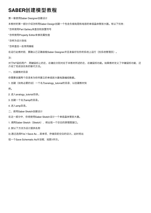
一般来说我们用saber2007我们会用到两个应用,一个是saber simulator这个是标准用来仿真的,另一个是saber sketch这个是用来画电路图的,但是呢,现在我们就用一个应用saber sketch 它有个快捷键可以调用saber simulator 就是下图这个。
PASS:不要懒网上教程一大堆多搜搜吧。
点开前的界面↓。
点开后的界面↓。
上面就介绍到那,我们继续下一步,器件的查找和放置。
下面是如何查找器件↓。
下面这个是放置器件↓器件的参数填写和一般的参数代表的意思,其一↓(在这有必要的提醒下对于英语不好的同学还是安装一个翻译软件比较好,我安装的是必应词典。
)器件的参数填写和一般的参数代表的意思,其二↓下面是saber不知道是那个版本的器件库介绍,我估计着是2006吧?但是我看了下都可以找到,我们就多了两个A开头的库(Aerospace和Automotive)。
呃,貌似有点乱,你们也就将就着看了吧!!!Saber Parts Gallery:Assembled by SubLater( 按中文意思归类,括号中是特殊部件和必要注释)★Characterized Parts Libraries 特性元件├─DX├─Diode 二极管(Zener 齐纳、Power 功率)├─BJT 三极管(Darlington 达林顿、Power 功率、Array 阵列)├─JFET/MOSFET/ 功率MOSFET 场效应管├─SCR/IGBT ,Switch 模拟开关器件├─Analog Multiplexer 模拟多路开关├─OpAmp 运算放大器├─Comparator 比较器├─ADC 、DAC├─Fuse 保险丝、Resettable Fuse 可复位保险丝(PPTC)├─Inductor 电感线圈├─Transformer 变压器├─Motor 电机模型├─PWM 控制器、PFC 元件├─Schmitt Trigger 施密特触发器├─Sensor 传感器├─Timer 定时器├─Transient Suppressor 暂态抑制器├─Voltage Reference 电压参考给定├─Voltage Regulator 电压调节器├─SL├─Diode 二极管(Zener 齐纳)├─BJT 三极管(Darlington 达林顿)├─JFET/ 电力MOSFET 场效应管├─SCR/IGBT ,Switch 模拟开关器件├─OpAmp 运算放大器├─Comparator 比较器================================ =============================== ★Integrated Circuit 集成电路IC├─Wire&Cable 导线和线缆( 导线、线缆、传输线) ├─DSP Building Block:DSP 数字信号处理单元( 和采样离散控制单元一样)├─Data Conversion 数据转换单元├─ADC 、DAC├─Data Acquisition System 数据获取元件├─Sample&Hold Amplifier 采样- 保持放大器├─Sample Data Conversion Block 采样数据转换单元( 和采样离散控制单元类似)├─Digital Block 数字电路单元├─Digital Source 置位信号源├─Gate 门电路├─Comparator 比较器├─Multiplexer:MUX 数据选择器├─Demultiplexer:DeMUX 数据分配器├─Flip-Flop&Latch:FF 双稳态触发器、锁存器├─Counter 计数器├─Register 寄存器Logic Clock 逻辑时钟BJT,Logic Case,TransistorSwitch 开关Adder,Full 1 bit 加法器Buffer 缓冲器(Logic 逻辑、Tri-State 三态) PWM 输出├─Power&Ground 直流电源和接地├─Electrical Source 交流信号源├─Voltage Source 电压源(Controlled 受控) ├─Current Source 电流源(Controlled 受控) ├─Passive Element 无源器件├─Capacitor 电容├─Inductor&Coupling 电感线圈、耦合变压器├─Resistor 电阻Piecewise Linear Conductance 分段线性电导Short 短接线├─Semiconductor Device 半导体器件├─Diode 二极管(Zener 齐纳)├─BJT 三极管(Power 功率)├─JFET/MOSFET 场效应管(Power 功率)├─Thyristor 晶闸管/IGBT 开关管├─OpAmp 运算放大器├─Transmission Line 传输线├─Voltage Comparator 电压比较器├─Voltage Controlled Oscillator 压控振荡器================================ =============================== ★★Power System 电力系统( 基本就是MAST Parts Library 中的Electronic、再加上Schmatic Design 、Source PowerGround 、Thermal Devices)├─Behavioral Compensastor 行为补偿单元├─Control System 控制系统├─Data Conversion 数据转换单元├─Digital Block 数字电路单元├─Electrical 电路单元├─Electro-Mechanical 机- 电系统├─Functional Element 功能单元├─Instrument 仪器├─Graphical Modeling 图形化建模├─Interface Model 变量接口模块├─Source,Power&Ground 交流信号源,直流电源和接地├─Passive Element 无源元件├─Semiconductor Device 半导体器件├─OpAmp 运算放大器├─Voltage Comparator 电压比较器├─Voltage Regulator 电压调节器├─PWM Control:PWM 控制器├─Thermal Device 发热元件├─Schematic Design 原理图设计================================ =============================== ★Control System 控制系统├─Continuous Control Block 连续控制单元├─Control System Source 控制信号源├─Signal Combiner 信号综合点├─Function 数学函数(+-*/ 算术运算、舍入函数、三角函数)├─Derivative 微分器、Integrator 积分器├─Nonlinear 非线性函数├─Relational Operator 关系运算符Biquadratic Filter 双二次滤波器DC Motor w/Var Output 直流电机w/Var 输出Gain 增益PProportional-Integral:PI 控制器传递函数(Rational Polynomial 有理多项式/Zero_Pole 零极点形式)State Space 状态空间表达式Lag 滞后/Lead-Lag 超前- 滞后环节├─Digital Logic Block 逻辑运算单元├─AND(NAND),OR(NOR),NOT,XOR(XNOR) 逻辑运算├─Interface Model 变量接口模块├─Technology 物理量<->var,var<->Z├─Sampled Data Control Block 采样离散控制单元(Z 域)├─Z Domain Source:Z 域信号源├─Algebraic:Z 域算术运算├─Linear Combination 线性综合点├─Adder 加法器、Subtractor 减法器、Multiplier 乘法器├─Amplifier 放大器├─Comparator 比较器├─Modulator 调制器、Delta Modulator 三角调制器├─Differentiator 微分器、Integrator 积分器├─Interface 接口模块(var<->Z)(SDS)├─Rational Polynomial 有理多项式├─Miscellaneous 杂项├─ADC 、DAC├─Counter 计数器├─Integral Decimation├─RMS Voltage 输入电压方均根rms( 即有效值eff)├─Sinc Singal:Sinc 信号├─State Delay 延迟器================================ =============================== ★★MAST Parts Library MAST 元件├─Control System 控制系统( 基本是从Control System 中抽取的常用单元)├─Continuous System 连续控制单元├─Digital Logic Block 逻辑运算单元├─Interface Model 变量接口模块├─Sampled Data Control Block 采样离散控制单元├─Electrical 电路单元(Electrical 电路单元和独立的Power System 电力系统并无重复)├─Wire&Cable 导线和线缆(Wire 导线、Cable 线缆、Transmission Line 传输线)├─Circuit Protection Device 电路保护装置(Fuse 保险熔丝、Resettable Fuse 可复位保险(PPTC))├─Energy Source&Stroage 能量来源和存储装置(Battery 电池(Lead-Acid 铅酸Li-ion 锂离子) 、Fuel Cell 燃料电池、SuperCapacitor 超大电容)├─Switch&Relay 开关和继电器├─Simple Switch 简单开关├─Multi Pole or Throw Switch 多刀/ 多掷开关├─Switch Driver 开关驱动器├─Relay 继电器├─Electro-Mechanical 机- 电系统├─Alternator 交流发电机├─Generator 直流发电机├─Motor 直流、交流电动机模型├─Motor Control Component 电机控制部件├─Motor Driver 电机驱动器├─Motor 电机部件├─Solenoid Building Block 螺线管├─Damper 阻尼器├─Electromagnet 电磁铁├─Winding 线圈、绕组├─Magnetic Core 磁芯├─Magnetic Actuator 励磁器├─Mass 重物├─Spring 弹簧├─Stop 制动├─Switch&Relay 开关和继电器├─Simple Switch 简单开关├─Multi Pole or Throw Switch 多刀/ 多掷开关├─Switch Driver 开关驱动器├─Relay 继电器├─Electronic 电子系统( 除了行为补偿单元是Power System 中的外,其他都是从Integrated Circuit 中抽取的常用单元)├─Behavioral Compensator 行为补偿器├─Wire&Cable 导线和线缆(Wire 导线、Cable 线缆、Transmission Line 传输线)├─DSP Building Block:DSP 数字信号处理单元├─Data Conversion 数据转换单元├─Digital Block 数字电路单元├─Electrical Source 交流信号源├─Voltage Source 电压源(Controlled 受控)├─Current Source 电流源(Controlled 受控)├─Functional Element 功能单元├─Power Device 功率元件├─Voltage Controlled Oscillator 压控振荡器DC/DC Convertor:DC/DC 变换器Three Phase Voltage Source 三相电压源Voltage Gain 电压增益、Voltage Summer 加法器、Voltage Subtractor/Difference 减法/ 差分器、Voltage Multiplier 乘法器Selector Switch 选择开关Constant Power Load 恒定功率负载Resistor 电阻Ideal 3-pin HyperModel: 理想3 端HyperModel Ramp Oscillator 斜坡振荡器├─Ideal Functional Element 理想功能单元├─Pole&Zero 零极点模型├─Switch 理想开关├─Two Port Block 双口网络├─Voltage Controlled Oscillator 压控振荡器Delay,Ideal 理想电压延迟Diode,Ideal 理想二极管MOSFET,P Ideal/N Ideal 理想P/N MOSFET 场效应管SCR,with logic gate 理想SCR 、Switch 开关、Power Semiconductor 功率半导体OpAmp,Ideal 理想OpAmp 运算放大器PWM Averaged Continuous,Ideal Logic Out: 理想PWM 控制器Sample and Hold,Ideal 理想采样- 保持器Short 理想短接线Transcapacitor,LinearVoltage Clamp 理想电压箝位Voltage Gain 理想电压增益、Voltage Summer 加法器、Voltage Subtractor/Difference 减法/ 差分器、Voltage Multiplier 乘法器├─Instrument 仪器├─Detection 检测仪器├─Voltage Limit 电压限幅、Current Limit 电流限幅├─Var Limit:var 限幅├─Measurement 测量仪器├─Frequency 频率(Frequency Capture Time 频率捕获时间、Rise/Fall Time上升/ 下降时间、Period 周期、Duty Cycle 占空比、Jitter 抖动)├─Peak 峰值、Average 平均值、RMS 均方根├─Interface 变量接口单元(Electrical 电量<->var)├─Power&Ground 直流电源和接地├─Passive Element 无源元件├─Semiconductor Device 半导体器件├─OpAmp 运算放大器├─Voltage Comparator 电压比较器├─Voltage Regulator 电压调节器├─PWM Control:PWM 控制器├─Graphical Modeling 图形化建模├─Analog Model Synthesis 模拟系统模型( 从PlotFile)├─Electrical Modeling 电路系统模型├─Control Modeling 控制模型(S 域、频域)├─Z Domain Modeling:Z 域模型├─Interface Model 变量接口单元(Technology 物理量<->var ,var<->Z 域)├─Interface,Micro-Controller 数据接口微控制器(SMCI)├─Address I/O Port 地址IO 端口、Data I/O Port 数据IO 端口├─Analog Input 模拟量输入端口、PWM Output:PWM 数字量输出端口├─Serial I/O Port 串行IO 端口、BUS Control Port 总线控制端口├─Magnetic 磁路元件├─Inductor&Coupling 电感线圈、耦合变压器├─Meterial Compoent 磁材料├─Magnetic Source 磁源Magnetic Core 磁芯Magnetic Actuator 励磁器Magnetic Short 磁短接线Winding 绕组├─Schematic Design 原理图设计├─Border 页面边界├─Connector 页间连接点├─直流电源和接地├─SamePage/OffPage 同层( 小模块, 即Symbol) 输入输出连接点,Hierarchical 下层( 大模块, 即Hierarchy Symbol) 输入输出连接点Saber Include File Saber 头文件元件( 全局变量) ├─检测Sensor 传感器、Transducer 变送器├─Source 交流信号源、Power 直流电源和Ground 接地├─Thermal Device 发热元件好了到了这,怎么添加器件和器件库就介绍完了。
SABER创建模型教程
SABER创建模型教程第⼀章使⽤Saber Designer创建设计本教材的第⼀部分介绍怎样⽤Saber Design创建⼀个包含负载电阻和电容的单级晶体管放⼤器。
有以下任务:*怎样使⽤Part Gallery来查找和放置符号*怎样使⽤Property Editor来修改属性值*怎样为设计连线*怎样查找⼀些常⽤模板在运⾏此教材前,要确认已正确装载Saber Designer并且准备好在你的系统上运⾏(找系统管理员)。
注:对于NT⿏标⽤户:两键⿏标上的左、右键应分别对应于本教材所述的左、右键⿏标功能。
如果教材定义了中键⿏标功能,还介绍了完成该任务的替代⽅法。
⼀、创建教材⽬录你需要创建两个⽬录来为你所建⽴的单级放⼤器电路编组数据。
1. 创建(如有必要的话)⼀个名为analogy_tutorial的⽬录,以创建教材实例。
2. 进⼊analogy_tutorial⽬录。
3. 创建⼀个名为amp的⽬录。
4. 进⼊amp⽬录。
⼆、使⽤Saber Sketch创建设计在这⼀部分中,你将使⽤Saber Sketch设计⼀个单级晶体管放⼤器。
1. 调⽤Saber Sketch(Sketch),将出现⼀个空⽩的原理图窗⼝。
2. 按以下⽅法为设计提供名称3) 通过选择File>Save As …菜单项,存储⽬前空⽩的设计。
此时将出现⼀个Save Schematic As对话框,如图1所⽰。
图 12) 在File Name字段输⼊名称Single_amp。
3) 单击OK。
3. 检查Saber Sketch⼯作⾯1)将光标置于某⼀图符上并保持在那⾥。
会显⽰⼀个⽂字窗⼝来识别该图符。
在⼯作⾯底部的Help字段也可查看有关图符的信息2)注意有⼀个名为Single_amp的Schematic窗⼝出现在⼯作⾯上。
三、放置部件在教材的这⼀部分你将按图2所⽰在原理框图上放置符号。
图中增加了如r1、r2等部件标号以便参照。
图 2 单级晶体管放⼤器部件布局1.按以下⽅式查找和放置npn晶体管符号:1) 单击Parts Gallery图符出现Parts Gallery对话框,如图3所⽰。
Saber使用手册
Saber使⽤⼿册第⼀章使⽤Saber Designer创建设计本教材的第⼀部分介绍怎样⽤Saber Design创建⼀个包含负载电阻和电容的单级晶体管放⼤器。
有以下任务:*怎样使⽤Part Gallery来查找和放置符号*怎样使⽤Property Editor来修改属性值*怎样为设计连线*怎样查找⼀些常⽤模板在运⾏此教材前,要确认已正确装载Saber Designer并且准备好在你的系统上运⾏(找系统管理员)。
注:对于NT⿏标⽤户:两键⿏标上的左、右键应分别对应于本教材所述的左、右键⿏标功能。
如果教材定义了中键⿏标功能,还介绍了完成该任务的替代⽅法。
⼀、创建教材⽬录你需要创建两个⽬录来为你所建⽴的单级放⼤器电路编组数据。
1. 创建(如有必要的话)⼀个名为analogy_tutorial的⽬录,以创建教材实例。
2. 进⼊⽬录。
3. 创建⼀个名为amp的⽬录。
4. 进⼊amp⽬录。
⼆、使⽤Saber Sketch创建设计在这⼀部分中,你将使⽤Saber Sketch设计⼀个单级晶体管放⼤器。
1. 调⽤Saber Sketch(Sketch),将出现⼀个空⽩的原理图窗⼝。
2. 按以下⽅法为设计提供名称3) 通过选择File>Save As …菜单项,存储⽬前空⽩的设计。
此时将出现⼀个Save Schematic As对话框,如图1所⽰。
图 12) 在File Name字段输⼊名称Single_amp。
3) 单击OK。
3. 检查Saber Sketch⼯作⾯1) 将光标置于某⼀图符上并保持在那⾥。
会显⽰⼀个⽂字窗⼝来识别该图符。
在⼯作⾯底部的Help字段也可查看有关图符的信息2) 注意有⼀个名为Single_amp的Schematic窗⼝出现在⼯作⾯上。
三、放置部件在教材的这⼀部分你将按图2所⽰在原理框图上放置符号。
图中增加了如r1、r2等部件标号以便参照。
图 2 单级晶体管放⼤器部件布局1. 按以下⽅式查找和放置npn晶体管符号:1) 单击Parts Gallery图符出现Parts Gallery对话框,如图3所⽰。
saber非线性电感参数设置

Saber非线性电感1:ref标识2:n 绕线匝数;3:nk 绕组耦合系数;(-1 <= nk <= 1) 4:r 绕组直流电阻值,单位欧姆;5:area 磁芯截面积Ae,单位平方米;6:len_fe 磁路长度,单位米;7: len_air 气隙长度,单位米;8:matl 磁芯材质8:b0 初始磁通密度9:sf层叠因子10:tempc核心模型的温度,单位°C11:rth_ja 从结点到环境热阻,单位(°C/W)12: rth_jc结间热阻,单位(°C/W)13: rth_sh外部散热器的热阻,单位(°C/W)14: temp 环境温度15: include stress 应力;关闭应力测量include_stress = 0 Saber_model模型1:ui初始磁导率2:uhc矫顽力相对渗透率3:bmax最大磁通密度,单位T or G4:hmax H最大值,单位A•t/m or Oe5:bsat饱和磁通密度,单位T or G6:hsat H饱和值,单位A•t/m or Oe7:br剩余磁通密度,单位T or G8:hc矫顽力,单位A•t/m or Oe9:ptemp定义模型参数的温度,单位°C10:tau B与H频率相关的时间常数,单位s11:taulim频率依赖性限制,单位sRatings最大额定值1:pdmax_ja与rth_ja最大耗散功率,单位W2: pdmax_jc与rth_jc和rth_hs最大耗散功率,单位W 3: tjmax内部最高温度,单位°C4: tjmin内部最低温度,单位°C5: imax最大的绕组电流,单位A6: vmax最大的绕组电压,单位Vja_model Jiles Atherton模型的参数1:a形状参数2:alpha平均场参数3:c弯曲常数4: k钉扎常数5: ms饱和磁化强度,单位A/m6:ptemp温度,α,C,K和MS,单位°C7:tau B与H频率相关的时间常数,单位s8:taulim频率依赖性限制,单位s。
Saber2006中文手册

5
3) 单击 OK。
4) 单击 Search 按键。
5) 在 Available Parts 表中,选择 Capacitor(一)。
6) 单击 place 按键放置 C 符号。
7) 如图 2 所示放置符号。如下可旋转符号 180°。
* 将光标移至符号上以便选择该符号。
* 按下并保持住鼠标右键以便引出上托符号菜单。选择 Rotate>180 菜单
7) 单击 place 按钮 5 次来放置 5 个电阻。
8) 通过单击 Saber Sketch Icon Bar 中的 Toggle Grid 图符 图窗口中打开网格。
9) 将 5 个电阻按图 2 所示放置在晶体管周围,步骤如下: *一一将鼠标光标放置在每个电阻上。 *按下并保持鼠标左键。 *将部件拖至合适的位置并释放鼠标。
Category Name
/
Search String
V_dc
1) Parts Gallery Preferences 表格中参数设定值同上。单击 Search 按
钮
2) 在 Available Parts 表中,选择 Voltage Source, Constant.
单击 Place 按钮放置 V_dc 符号。
图符。在工作面底部的 Help 字段也可查看有关图符的信息 2) 注意有一个名为 Single_amp 的 Schematic 窗口出现在工作面上。
三、放置部件
在教材的这一部分你将按图 2 所示在原理框图上放置符号。图中增加了如 r1、r2 等部件标号以便参照。
2
图2
单级晶体管放大器部件布局
1. 按以下方式查找和放置 npn 晶体管符号:
,在原理
4
Saber仿真软件入门教程

SABER讲义第一章使用Saber Designer创建设计本教材的第一部分介绍怎样用Saber Design创建一个包含负载电阻和电容的单级晶体管放大器。
有以下任务:*怎样使用Part Gallery来查找和放置符号*怎样使用Property Editor来修改属性值*怎样为设计连线*怎样查找一些常用模板在运行此教材前,要确认已正确装载Saber Designer并且准备好在你的系统上运行(找系统管理员)。
注:对于NT鼠标用户:两键鼠标上的左、右键应分别对应于本教材所述的左、右键鼠标功能。
如果教材定义了中键鼠标功能,还介绍了完成该任务的替代方法。
一、创建教材目录你需要创建两个目录来为你所建立的单级放大器电路编组数据。
1. 创建(如有必要的话)一个名为analogy_tutorial的目录,以创建教材实例。
2. 进入analogy_tutorial目录。
3. 创建一个名为amp的目录。
4. 进入amp目录。
二、使用Saber Sketch创建设计在这一部分中,你将使用Saber Sketch设计一个单级晶体管放大器。
1. 调用Saber Sketch(Sketch),将出现一个空白的原理图窗口。
2. 按以下方法为设计提供名称3) 通过选择File>Save As …菜单项,存储目前空白的设计。
此时将出现一个Save Schematic As对话框,如图1所示。
图 12) 在File Name字段输入名称Single_amp。
3) 单击OK。
3. 检查Saber Sketch工作面1)将光标置于某一图符上并保持在那里。
会显示一个文字窗口来识别该图符。
在工作面底部的Help字段也可查看有关图符的信息2)注意有一个名为Single_amp的Schematic窗口出现在工作面上。
三、放置部件在教材的这一部分你将按图2所示在原理框图上放置符号。
图中增加了如r1、r2等部件标号以便参照。
图 2 单级晶体管放大器部件布局1.按以下方式查找和放置npn晶体管符号:1) 单击Parts Gallery图符出现Parts Gallery对话框,如图3所示。
- 1、下载文档前请自行甄别文档内容的完整性,平台不提供额外的编辑、内容补充、找答案等附加服务。
- 2、"仅部分预览"的文档,不可在线预览部分如存在完整性等问题,可反馈申请退款(可完整预览的文档不适用该条件!)。
- 3、如文档侵犯您的权益,请联系客服反馈,我们会尽快为您处理(人工客服工作时间:9:00-18:30)。
corenl corenl (Nonlinear Magnetic Core with Temperature Dependence)Associated Symbols:corenlLicense Requirements:OPT_TEMPLATE_LIBPart Category:Magnetic TemplatesRelated Topics:Introduction to Magnetic TemplatesMagnetic Core Characterization Toolcore - linear magnetic corecorenl2 - nonlinear magnetic core with hysteresiswind - windingFunctional DescriptionThe corenl template models a nonlinear magnetic core (note the magnetic connection points). It is normally used with the windtemplate to model an inductor or a transformer in an electricalcircuit. Because of the proprietary information of the Jiles-Atherton model, this template is encrypted so you can’t read it past theargument declarations (see Model Arguments).Template Description SectionsConnection PointsSymbol PropertiesModel ArgumentsStress ArgumentsPost-Processing InformationExport VariablesExternal ParametersModel DescriptionUsage NotesNetlist ExamplesAdditional ExamplesReferencescorenl Connection PointsName Type Descriptionp magnetic positive end of core m magnetic negative end of corecorenlp mNonlinear magnetic core (corenl)corenl corenl Symbol PropertiesPropertyprimitive Description:This symbol calls the templatecorenl, which models a nonlinearmagnetic core. It is normally usedwith the wind template to function asan inductor or a transformer in anelectrical circuit. You must specifyeither a string value for the argumentmatl or specify numeric values for allthe other model arguments exceptptemp and tau. Specifying a value formatl overrides the values for model.Matl is a string specifying acommercially available core material;model allows you to specify a group ofcore characteristics at as manydifferent temperatures (ptemp) asdesired.ref Description:Suffix appended to a template namethat uniquely identifies a part in aschematic.Default:If not specified, will be assigned bythe schematic capture toolExampleInput:Can be any alpha-numeric string len Description:Magnetic path lengthDefault (units):Value required (m)ExampleInput:1.27marea Description:Cross-sectional area of magnetic pathDefault (units):Value required (m2)ExampleInput:5.9e-5matl Description:Core material name (from library).This overrides the saber_modelproperty. See Usage Notes.Default (units):none (—)Example Input:“3c8” (Note that the quotation marks are required.)sf Description:Stacking factor adjustment to area ina laminated core. This is the ratio ofarea that is magnetically active.Default (units):1 (—)Example Input:1Propertycorenl saber_model Description:saber_model automatically maps tothe template argument model, whichis a grouping of ten B vs H modelarguments defining a material at aspecified temperature (ptemp).Default (units):none (—)Example Input:[(ptemp=27,ui=2700,hc=0.2, uhc=6000,br=1000,hsat=2.5, bsa t=4500,hma x=15, bma x=4800, tau=0.6u,taulim=50n),(ptemp=100,ui=2100,hc=0.2, uhc=4300,br=900,hsat=2.0, bsat=3300,hmax=15,bmax=3600, tau=0.6u,taulim=50n)]ja_model Description:Jiles-Atherton model arguments, usedonly if matl and saber_model areundefined.Default (units):none (—)b0Description:Initial flux density (B) in addition toanhysteretic. Units depend on unitsselection.Default (units):0(G if units=gauss; T if units=si)Example Input:0Propertytempc Description:Core model temperatureDefault (units):undef (°C)ExampleInput:37units Description:System of units for nonlinearmagnetic properties saber_modeland b0.Default (units):gauss (—)Values:gausssiExampleInput:sigeo_units Description:Allows the geometry units (len,area) to be specified in inch, meter, orcm.Default (units):meter (—)ExampleInput:cmtemp Description:Ambient temperature for temperatureeffects (see External Parameters).Default (units):27 (°C)Example Input:32Propertycorenl ratings Description:Structure of maximum ratings for thisdevice.Default (units):Available stress ratings for this model are: pdmax_ja, pdmax_jc, tjmax, tjmin, bmax. All values are set to undef by default (see Usage Notes).Example Input:(bmax=5k,pdmax_ja=.25,tjmax=1 50)rth_ja Description:Thermal resistance from junction toambient (see Usage Notes).Default (units):undef (°C/W)ExampleInput:0.2rth_jc Description:Thermal resistance from junction tocase (see Usage Notes).Default (units):undef (°C/W)ExampleInput:0.2rth_hs Description:Thermal resistance of an externalheat sink (see Usage Notes).Default (units):undef (°C/W)Example Input:0.2Propertypart_type Description:Part type string. Limited to 9characters.Default (units):mag core (—)ExampleInput:nonlin corepart_class Description:Part class string. Limited to 18characters.Default (units):nonlin generic (—)ExampleInput:componentinclude_ stress Description: A flag to allow stress analysis in thenetlisted template (see ExternalParameters).Default(units):1(—)ExampleInput:To turn off stress measurement:include_stress=0Propertycorenl corenl Model ArgumentsName Default Units/ValuesDescriptionmodel undef— a grouping of ten B vs H modelarguments defining a material ata specified temperature (ptemp)ui undef—initial relative permeabilityuhc undef—relative permeability at coercivelevel of H (hc). See MagneticHysteresis for more details.bmax undef T or G maximum value of B (unitsdepend on units selection). SeeMagnetic Hysteresis for moredetails.hmax undef A•t/m orOe maximum value of H (units depend on units selection). See Magnetic Hysteresis for more details.bsat undef T or G value of B at saturation (unitsdepend on units selection). SeeMagnetic Hysteresis for moredetails.hsat undef A•t/m orOe value of H at saturation; must be less than hmax (units depend on units selection). See Magnetic Hysteresis for more details.br undef T or G residual B (units depend onunits selection). See MagneticHysteresis for more details.hc undef A•t/m orOe coercive force (units depend on units selection). See Magnetic Hysteresis for more details.ptemp 27°C temperature at which model arguments are defined tau 0s time constant for B vs. H frequency dependence. taulimsfrequency dependence limit (taulim should be specified as much less than tau )ja_model[*][()]—grouping of Jiles-Atherton arguments (used only if matl and model are undefined) a undef —shape argument alpha undef —mean field argument c undef —domain wall flexing constant k undef —domain wall pinning constant ms undef A/m magnetization saturation ptemp 27°C temperature for a , alpha , c , k , and mstau 0s time constant for B vs. H frequency dependencetaulimsfrequency dependence limit (taulim should be specified as much less than tau )Name DefaultUnits/Valu esDescriptioncorenlcorenl Stress ArgumentsStress arguments are intended for use with the stress analysis, which is a part of the InSpecs Stress Analysis Option.DescriptionName Default Units/Valuesbmax undef T maximum flux densitytjmax undef°C maximum internal temperaturetjmin undef°C minimum internal temperaturepdmax_ja undef W maximum power dissipationwith rth_japdmax_jc undef W maximum power dissipationwith rth_jc and rth_hscorenl Post Processing InformationThe variables in the following table are available forpost-processing. You can specify them in a signal list or asarguments to the extract command.Name Type Units Descriptionmmf val mmf A•t magnetomotive forcehin val hm A•t/m magnetic field strength of Hacross the magnetic input pins mtotal val mm A/m total magnetizationhg val hg Oersted magnetic field strength of H he val hm A•t/m effective internal H field (acomputational variable usedinternal to the template) mirr val mm A/m irreversible magnetizationcorenl Export Variablespwrd, tempj, f, b, bgThese are post-processing variables that can be referenced at the next higher level of the hierarchy . mrevval mm A/m reversible magnetization temp_case val tc °Ccase temperature rth_hs_tjm ax val rth °C/Wmaximum heat sink thermal resistance f val f Wbflux (see Export Variables )b var bsi Teslamagnetic field density (see Export Variables )bg val bg Gaussmagnetic field density of B (see Export Variables )pwrd val p W instantaneous powerdissipation (see ExportVariables )tempj val tc °Cinstantaneous junctiontemperature (see ExportVariables )Name Type Units Descriptioncorenlcorenl External Parameterstemp, include_stressThese are global parameters declared in header.sin. You can assign values to them for an instance of this template (such as in a netlist) without affecting their global values in the rest of your design. For example, the following netlist statement allows you to change the simulation temperature to 58°C for corenl.e1 only: corenl.e1 b 0 = len=3e-2, area=6e-5, model=[(ui=2700,uhc=6000, bmax=4800, hmax=15, bsat=4500, hsat=2.5,br=1000, hc=0.2, ptemp=20, tau=50n), (ui=2100, uhc=4300, bmax=3600, hmax=15, bsat=3300, hsat=2.0, br=900, hc=0.2, ptemp=100, tau=50n)], units=gauss, temp=58corenl Model Description (the Jiles-Atherton Model) Hysteretic magnetization is characterized by the classic B-H curve described in the Magnetic Fundamentals topic Hysteresis. A basic simulation problem presented by hysteresis is that there is not a unique value of B for any given value of H.Anhysteretic magnetization provides a method for selecting a unique value of B for a given value of H. The principal uses of the anhysteretic value of B are:•to provide initial point values for B in a DC analysis•to provide an equilibrium point for a transient analysisThe Jiles-Atherton model (see the References) provides a workable characterization of anhysteretic magnetization. It consists of a mathematical approach to the theoretical anhysteretic behavior of a core material, given a few basic input arguments for the material. The J-A model derives both the anhysteretic characteristic and the major hysteresis loop for a given material. This procedure has been found to compare favorably with experimental results for many ferromagnetic materials.Since the value of B at time t is a function not only of the value of H at time t, but also of the initial values of H and B, this means that B 0 can assume any value within the hysteresis envelope, leading to a significant problem in a DC analysis. Even if H = 0 at t 0, B 0 can still lie anywhere between -B res and +B res , as shown in the following figure. Although selecting B 0 = 0 seems like a reasonable value, it can be grossly inaccurate if ⏐H 0⏐ is large. HB0+B res-B resEnvelope for values of B0Anhysteretic magnetization provides a more accurate method for selecting a unique value of B for a given value of H. This value of B lies between the upper and lower limits determined by the given value of H on the B-H curve. The principal advantage in using the anhysteretic value of magnetization is that it determines the same value of B for a given value of H regardless of whether H isincreasing or decreasing. This means there is no hysteresis—hence the name anhysteretic.The following equation describes the anhysteretic characteristic of a given material:M an = M s ·(coth[H eff /A] - A/H eff )where:H eff = H + α·M anM an = anhysteretic magnetizationcorenlHeff= effective magnetic field strengthMs= saturation magnetizationA = shape argument for magnetizationα = mean field argument for interdomain couplingThe J-A model represents the anhysteretic magnetization of a material as a state of magnetic equilibrium. This is an optimum configuration of magnetic characteristics, corresponding to a point of minimum internal energy.The curve for the anhysteretic level lies between the upper and lower curves of the major hysteresis loop and passes through the origin, as illustrated in the following figure.BHAnhysteretic magnetization levelThe most significant advantage of this curve is that it provides acontinuum of reasonable single values for Bfor arbitrary values ofH0. The corenl templates allows the selection of a value of Bthatdiffers from the anhystereticvalue, if desired: however, this is not generally recommended.This state of anhysteretic magnetization is represented by a value of magnetization, Man(which is related to flux density B) and lies between upper and lower hysteretic values of M (corresponding to upper and lower limits for values of B). The J-A model specifies atendency for these hysteretic values of M (M ≠ Man ) to approach Man.corenl Usage NotesIf the device is operating without a heat sink, use pdmax_ja for the power dissipation rating and rth_ja for the thermal resistance (rth_ja must be specified if you want the device temperature rise calculated).If the device is operating with a heat sink, use pdmax_jc for the power dissipation rating and a combination of rth_jc and rth_hs for the thermal resistance.This template is principally used as a “building block” template in conjunction with the wind template. There are threemutually-exclusive ways to specify characteristics of the corenl template:•The model argument allows you to specify values for permeability, flux density, field strength, and coercive force atone or more temperatures. You must specify values for eachargument contained within model.•The ja_model argument allows you to specify values for Jiles-Atherton arguments (which are less commonlyavailable).•The matl argument allows you to specify a string for a commercially-available core material. The library of modelsfor core materials contains characterization data for ferritecores, silicon-iron laminate cores, and permalloy cores (seecorenlcorenl References).Material Manufacturer Name String Name Ferrite Philips Components 3B7"3B7"Philips Components 3B9"3B9"Philips Components 3C6A"3C6A"Philips Components 3C8"3C8"Philips Components 3C85"3C85"Philips Components 3D3"3D3"Philips Components 3E2A"3E2A"Philips Components 3E5"3E5"Philips Components 3F3"3F3"Philips Components 4C4"4C4"Silicon-Iron Laminate Magnetic Metals 3% SiliconIron, 1 50 EI“si_re”Square Permalloy Magnetics Square Permalloy80, 50 038 5d“sq_perm_80”Specifying a value for matl overrides the values for model, and ja_model is used only if matl and model are undefined.corenl Netlist ExamplesThis example uses model to specify characteristics at two different temperatures (i.e., two values of ptemp), and specifies a value for the external parameter temp.corenl.e1 b 0 = len=3e-2, area=6e-5, model=[(ui=2700,uhc=6000, bmax=4800, hmax=15, bsat=4500, hsat=2.5,br=1000, hc=0.2, ptemp=20, tau=50n), (ui=2100, uhc=4300, bmax=3600, hmax=15, bsat=3300, hsat=2.0, br=900, hc=0.2, ptemp=100, tau=50n)], units=gauss, temp=58This example uses matl to specify a predefined,commercially-available core material.corenl.e2 c 0 = len=2.8e-2, area=5.9e-5, matl="3c8",tempc=37corenl Additional ExamplesListed below are different ways to specify a core model by changing the netlist entry, with a brief explanation of why each is useful. Refer to Section 3.4 of the MAST Reference Manual for more information on using the operators (.. -> and <-).•If all desired arguments are listed (the simplest specification for a core), use the following:corenl.e3 wb 0 = len=3e-2, area=6e-5,model=[(ui=2700, uhc=6000, bmax=4800, hmax=15,bsat=4500, hsat=2.5, br=1000, hc=0.2, ptemp=20,tau=50n)], tempc=60, units=gauss•If referring to a model specification in more than one netlist entry (useful where several cores will share the same model orsimilar models), use the following:corenl..model fred = [(ui=2700, uhc=6000,bma x=4800, hma x=15, bsa t=4500, hsa t=2.5, br=1000,hc=0.2, ptemp=20, tau=50n)]This example defines the fred model, and must appear beforecorenl any core that refers to it. The related example below uses thefred model with a length of 2 cm and an area of 0.5 cm2.corenl.e4 wb 0 = len=2e-2, area=5e-5, model=fred •If one model references another model (useful if a new model is similar to another model), use the following:corenl..ja_model duff = [(a=8.366, alpha=-100.8u,c=0.4500, k=14.2, ms=380777, ptemp=20, tau=600n,taulim=50n)]The duff model defined above is used with a length of 2 cmand an area of 0.5 cm2 as follows:corenl.e5 wb 0 = len=2e-2, area=5e-5,ja_model=duffcorenl References1.Soft Ferrite Cores Short Form Catalog, Philips Components,Magnetic Products Group, Saugerties, NY.2.Colonel William T. McLyman, Magnetic Core Selection forTransformers and Inductors, Marcel Dekker Inc., 1982.3.Tape Wound Cores Design Manual, TWC-400, Magnetics,Division of Sprang and Company, 900 E. Butler Road, Butler,PA, 16003.D.C.4.Jiles and D.L. Atherton, Theory of Ferromagnetic Hysteresis,Journal of Magnetism and Magnetic Materials, Vol. 61,1986.。