CX425小型光电传感器使用说明书
光电传感器使用说明
光电传感器使用说明一、光电传感器的工作原理和分类1. 光电二极管(Photodiode):它是一种常见的光电传感器,可将光信号转化为电流信号。
光电二极管通过感光面积的调整,可实现对不同光强的测量。
2. 光敏电阻(Light-dependent resistor,LDR):它是一种依靠光线照射而改变电阻值的传感器。
光敏电阻的电阻值与光线强度成反比关系,因此可以用来测量光线的亮度。
3. 光电三极管(Phototransistor):它结构上类似于普通的晶体管,但在基区和发射区之间加上了一个光敏区。
当光照射到光电三极管时,会产生电流放大效应,从而可以将光信号转化为电流信号。
4. 光电耦合器(Optocoupler):它是将光电二极管和晶体管封装到一个封装内,用光绝缘的方式实现输入与输出之间的电气隔离。
光电耦合器在电气隔离和信号传输方面有重要的应用,可以用于电路隔离、信号转换等。
二、光电传感器的安装和调试在安装和调试光电传感器时,需要注意以下几点:1.安装位置的选择:根据具体的应用需求,选择合适的安装位置。
要确保光线能够正常照射到传感器的感光面,避免遮挡和干扰。
2.供电电压的选择:根据传感器的额定电压和工作电压范围,选择适当的供电电源。
要确保供电电压的稳定性,以免对传感器的工作产生影响。
3.输出信号的接收和处理:根据传感器的输出信号类型和电平,选择合适的接收和处理电路。
可以通过模拟电路或数字电路来处理传感器的输出信号。
4.灵敏度的调节:根据具体的应用需求,调节传感器的灵敏度。
对于光电二极管和光敏电阻等传感器,可以通过调节外部电阻来实现。
三、光电传感器的应用领域1.自动控制:光电传感器可以用于自动控制系统,如照明控制、清晰度检测、颜色识别等。
通过检测环境光照的变化,实现对设备的自动控制。
2.测量仪器:光电传感器可以用于测量仪器中,如光谱仪、测量器等。
通过测量光线的强弱、波长等,实现对物理量的测量。
3.光通信:光电传感器可以用于光通信系统中,如光纤通信、光模块等。
光电传感器产品参数说明书

Photoelectric Sensors2.144BMOA Miniature Remote Amplifier SensorsNeed the precision of a laserphotoelectric sensor, but have no room to mount something that big? Ultra miniaturesensing heads down to 2 mmcan fit into applications wheremost sensors won’t. The BMOA component systems use an amplifier to power and control the signals from the sensing head, making it a unique alternative to typical fiber optic solutions. The BMOA component systems offer maximum flexibility with high flex cable versions for moving applications likerobotic arms. The systems can detect targets as small as 0.05 mm. The BMOAamplifiers make set-up and operation easy, using a simpledynamic teach function, or amanual push-button adjustment mode. Available in economical discrete or advanced analog outputversions to solve difficult applications.Features– Smallest sensing head in the industry– Laser-like precision to detect targets as small as 0.05 mm – High speed switching up to 5 kHz– 50 ms pulse stretching delay – Simple pushbuttonadjustment of dynamic teach function– Stability and Output Function LEDs– Discrete output versions PNP and NPN– Analog Output versions 0…10 Vdc and 4…20 mA – Din-rail or panel mountable Applications– Thread detection – Small part profiling – Robotic end-effectors– Semiconductor component detection– High performance alternative to fiber opticsBMOAMiniature Remote Amplifier SensorsBMO A01... amplifiers only.C o u r t e s y o f C M A /F l o d y n e /H y d r a d y n e ▪ M o t i o n C o n t r o l ▪ H y d r a u l i c ▪ P n e u m a t i c ▪ E l e c t r i c a l ▪ M e c h a n i c a l ▪ (800) 426-5480 ▪ w w w .c m a f h .c o m2.145t p76o amplifier connectoramplifier connectoramplifier connectorC o u r t e s y o f C M A /F l o d y n e /H y d r a d y n e ▪ M o t i o n C o n t r o l ▪ H y d r a u l i c ▪ P n e u m a t i c ▪ E l e c t r i c a l ▪ M e c h a n i c a l ▪ (800) 426-5480 ▪ w w w .c m a f h .c o mPhotoelectric Sensors2.146High SpeedBMO A01-I-PU-C-02BMO A01-I-NU-C-02SeriesDiscrete Output PNP Normally-open NPNNormally-open Analog Output 0...10 Vdc 4...20 mASupply VoltageVoltage Drop U d at I e Output Current (digital)Analog Output Type (Voltage)Analog Output Type (Current)Analog Output Load (voltage) min load Analog Output Load (current) Max Load Current Consumption I o (no load)Protections Response TimeSwitching FrequencyPulsed/Non-Pulsed Light Source Output FunctionOperating Temperature Range Degree of Protection per IEC 60529Sensitivity/Range Adjustment Power/Stability Indication Alarm Indication Output LEDHousing MaterialWeightConnection (to control system)10…30 Vdc< 2 V 100 mA 45 mAShort Circuit, Reverse Polarity100 µs 5 KHz Non-PulsedLight/Dark Selectable -10° C to +55° CIP 65Teach-in and ManualGreen LED Yellow LED ABS 55 g2 m PVC Cable ,3 x 26 AWGq w e rBMOAMiniature Remote Amplifier SensorsSensitivity settingAUT – the amplifier will determine the best setting for the application.MAN – this allows you to fine-tune the settings or manually adjust the sensor for difficult applications.Wiring DiagramsOutput GNDOutput GNDrC o u r t e s y o f C M A /F l o d y n e /H y d r a d y n e ▪ M o t i o n C o n t r o l ▪ H y d r a u l i c ▪ P n e u m a t i c ▪ E l e c t r i c a l ▪ M e c h a n i c a l ▪ (800) 426-5480 ▪ w w w .c m a f h .c o mFiber Optics/photoelectricObject Resolution for Diffuse Sensors42-2-4-6-8Y(mm)055M, 06TM & 66RMYMeasuring Arrangement:900a standard resolution amplifier.04SM, 05TM & 66RMthe beam at certain ranges.Sensing Distance for Diffuse Sensors0.8% 1.6% 3.1% 6.3% 12.5% 25% 50% 100%Absolute Mode (ABS)This mode offers the maximum accuracy for allapplications. The amplifier will offer 8 stages ofCourtesyofCMA/Flodyne/Hydradyne▪MotionControl▪Hydraulic▪Pneumatic▪Electrical▪Mechanical▪(8)426-548▪www.cmafh.co m。
OMRON光电传感器操作手册
݊Ёӏϔ䬂 ᣝV
᳝Ꮉӊ⢊ᗕϟ
Ꮉ 7(&+ ----
݊Ёӏϔ䬂 ᣝV
Ā----ā䮾⚕
Ā----ā䮾⚕
83 581 '2:1
㟇581
᮴Ꮉӊ⢊ᗕϟ
5)&+ 䯜ؐ
݊Ёӏϔ䬂 ᣝV
7+58
䯜ؐ
ĀᏆ䆒ᅮདⱘ䯜ؐā䮾⚕
ĀᏆ䆒ᅮདⱘ䯜ؐā䮾⚕
ফܝ䞣
䯜ؐ
ফܝ䞣
䯜ؐ
䆒ᅮ㒧ᴳৢˈ䖨ಲࠄ ᪡ࠡⱘᰒ冫
406
᳔ᮄѻક䌘᭭䇋ⱏᔩ
᪡㆛⬉ܝӴᛳ఼
ܝ ⬉ Ӵ ᛳ ఼
⊼
ৠᯊᣝV
䆒ᅮࡼᓣ
ৃҹ䗮䖛ߛᤶᓔ݇䆒ᅮࡼᓣDŽ ࡼᓣ ᪡ /g21 'g21
/
ߎॖᯊⱘ䆒ᅮ
>䖨ಲ߱ྟܝ䞣ᯊ@
'2:1 02'(
ܹܝᯊ21 䙂ܝᯊ21
⊼ᣝ02'(䬂ৢ䇋ゟेᣝ'2:1䬂DŽ
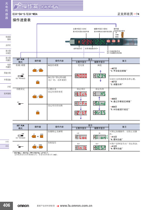
显示 主数字显示
/2&
辅数字显示
21
备注 可锁定按键操作,以防止误操 作。 →413页 “6.便利功能” 可将产品恢复至出厂设定状态。 →413页 “6.便利功能”
UP
MODE
ᡔᴃ㆛ ᪡㆛
6(7
UP DOWN
初始复位
,1,7
<(6"
* E3X-MDA□/E3X-DA□TW-S/E3X-DA□AT-S除外。 这些机型没有功率调谐指示灯,但备有动作指示灯(ch2)。
䗮䖛ᬍ䆒ᅮݙᆍDŽ
ࡳ㛑ৡ鹵
ࡼᓣ Ẕ⌟ࡳ㛑
䆒ᅮݙᆍ ᰒ冫
ܹܝᯊ21˖ǃ䙂ܝᯊ21˖ ᳔ᖿ˖ǃ催䗳˖ǃᷛ˖ޚǃ催㊒ᑺ˖ǃ ᖂߚࡼ˖ ҙ催ࡳ㛑ൟ
《小型光电传感器CX》word版
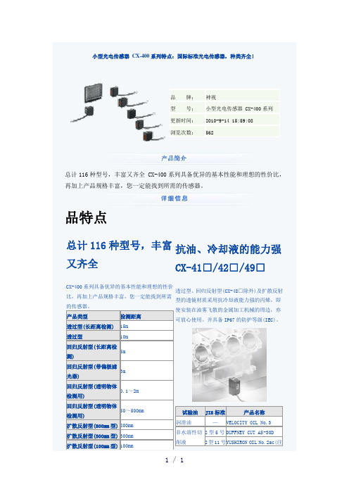
总计116种型号,丰富又齐全 CX-400系列具备优异的基本性能和理想的性价比,再加上产品规格丰富,您一定能找到所需的传感器。
品特点总计116种型号,丰富又齐全CX-400系列具备优异的基本性能和理想的性价比,再加上产品规格丰富,您一定能找到所需的传感器。
产品类型检测距离透过型(长距离检测)15m透过型10m回归反射型(长距离检测)5m回归反射型(带偏极滤光器)3m回归反射型(透明物体检测用)0.1~2m回归反射型(透明物体检测用)50~500mm扩散反射型(800mm型)800mm扩散反射型(300mm型)300mm扩散反射型(100mm型)100mm 抗油、冷却液的能力强CX-41□/42□/49□透过型、回归反射型(CX-48□除外)及扩散反射型的透镜材质采用抗冷却液能力强的丙烯。
即使安装在油雾飞散的金属加工机械的周边,亦可放心使用。
并具备IP67的防护等级(IEC)。
试验油JIS标准产品名称润滑油—VELOCITY OIL No.3非水溶性切削液2型5号DUFFNEY CUT AS-30D2型11号Y USHIRON OIL No.2ac(注IP67注:安装时,请避免使清洗液沾到附带于CX-48□中的反射镜上。
检测玻璃瓶检测小型药片检测薄型饼干基本性能红外光束之强光束 CX-412以2%以下的应差可检测小到0.4mm 的高低差 CX-441/443实现检测距离为15m 的长距离检测。
强劲的穿透力,亦可用于包装物内部的检测等。
相对于原有型号,先进的光学系统将检测性能提高约2.5倍。
即便是小到0.4mm 的高低差亦可准确地检测出。
不易受颜色的影响 CX-441/443回归反射型(带偏极滤光器) CX-491无论是白色工件,还是黑色工件,均可按照几乎相同的距内置偏极滤光器,就连镜面体亦可稳定检测。
离进行检测。
即使流水线上存在不同颜色的工件,需要切换工序时,也无需使用调节器调节。
设定距离为50mm的白色无光泽纸张和亮度为5的无光泽纸张(灰色)之间的检测距离差低于1%。
光电开关传感器说明书
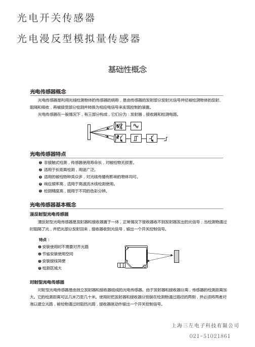
光电开关传感器 光电漫反型模拟量传感器
特点: 1 长距离检测,高精度检测 2 可检测小物体 3 不受被检物的形状、颜色和材质影响 4 适用恶劣工作环境
回归反射型光电传感器 回归反射型光电传感器是把发射器和接收器装入同一个装置内,在其前方装一块反光板,利用反射原理完成光电
控制作用的光电传感器。正常情况下,发射器发出的光被反光板反射回来被接收器收到;一旦光路被检测物挡住,接 收器检测的光信号有变化,光电传感器就动作,输出一个开关控制信号。
特点: 1 安装使用时便于光路对齐 2 相对于对射式光电传感器,节省安装使用空间 3 安装接线简便 4 不受被检物的形状、颜色和材质影响
上海三左电子科技有限公司 021-51021861
光电开关传感器 光电漫反型模拟量传感器
应用实例
光电式传感器主要利用光电效应检测物体。 在环境条件比较好、无粉尘污染的场合,可采用光电式传感器。 光电式传感器有检测距离远,对被检测物无影响的特性,广泛用于电子行业、食品饮料行业、包装物流行业等。
检测集成电路块
规格表中的检测距离是在检测目标为100*100mm、200*200mm、300*300mm的白色无光泽纸的条件下测得。
对射型 将发射器和接收器面对面安装,并连接电源。 调节发射器和接收器的上下左右位置,使中心对正,使指示灯状态变化。 可靠安装两者后并校对使其检测到目标。
发射器
回归反射型(包括偏振反射型) 将传感器和反光板镜面对面安装后,连接电源。 调节反射面的上下左右位置,传感器的指示灯状态变化。 可靠安装两者后并校对并使其检测到目标。
光电开关传感器
光电漫反型模拟量传感器
基础性概念
光电传感器概念
cx491光电参数

cx491光电参数CX491光电参数是指CX491型号的光电开关的性能指标。
光电开关是一种利用光电工作原理进行信号检测和测量的装置,广泛应用于自动化控制系统中。
CX491光电开关具有以下一系列的参数和特性。
1.检测距离:CX491光电开关的检测距离是指传感器能够在光照条件下正确检测到目标物体的最大距离。
该参数通常以米(m)为单位进行表示。
CX491光电开关的检测距离通常在几厘米到几米之间,具体取决于传感器的工作原理和设计。
2.工作电压:CX491光电开关的工作电压是指传感器正常工作所需的电压范围。
该参数通常以伏特(V)为单位进行表示。
CX491光电开关的工作电压通常为DC 10-30V,适用于工业自动化控制系统中常见的24V直流电源。
3.输出类型:CX491光电开关的输出类型是指传感器在检测到目标物体后输出的信号类型。
常见的输出类型包括PNP型(正逻辑)和NPN 型(负逻辑)。
PNP型传感器在检测到目标物体时输出高电平信号(通常为电源电压),而NPN型传感器在检测到目标物体时输出低电平信号(通常为零电位)。
4.输出状态:CX491光电开关的输出状态是指传感器在检测到目标物体时输出的信号状态。
常见的输出状态包括有源输出和无源输出。
有源输出是指输出端需要提供额外的电源来驱动负载,而无源输出则是指输出端直接输出开关信号,不需要额外的电源。
5.响应时间:CX491光电开关的响应时间是指传感器从检测到目标物体到输出信号发生变化的时间。
响应时间通常以毫秒(ms)为单位进行表示。
CX491光电开关的响应时间通常在几毫秒到几十毫秒之间,具体取决于传感器的工作原理和设计。
6.环境温度:CX491光电开关的环境温度是指传感器正常工作的环境温度范围。
该参数通常以摄氏度(℃)为单位进行表示。
CX491光电开关的环境温度通常为-25℃至+55℃,适用于大多数工业环境。
7.隔离电压:CX491光电开关的隔离电压是指开关输入和输出之间的电气隔离能力。
RightSight 微型光电传感器指南说明书
Installation InstructionsOriginal InstructionsRightSight Miniature SensorsCatalog Numbers 42EF-D2JBAK-A2, 42EF-D2JBAK-F4, 42EF-D2KBAK-A2, 42EF-D2KBAK-F4, 42EF-D2MPAK-A2, 42EF-D2MPAK-F4,42EF-D2MPAK-Y4, 42EF-P2JBB-A2, 42EF-P2JBB-F4, 42EF-P2KBB-A2, 42EF-P2KBB-F4, 42EF-P2MPB-A2, 42EF-P2MPB-F4, 42EF-P2MPB-Y4, 42EF-R2JBB-F4, 42EF-R2JBBT-A2, 42EF-R2JBBT-F4, 42EF-R2KBB-A2, 42EF-R2KBB-F4, 42EF-R2KBB-Z31, 42EF-R2KBBT-A2, 42EF-R2KBBT-F4, 42EF-R2MEB-F4, 42EF-R2MNB-A2, 42EF-R2MNB-F4, 42EF-R2MNB-Y4, 42EF-R2MNBT-A2, 42EF-R2MNBT-F4, 42EF-R2MPB-A2, 42EF-R2MPB-A5, 42EF-R2MPB-A6, 42EF-R2MPB-F4, 42EF-R2MPB-Y4, 42EF-R2MPBT-A2, 42EF-R2MPBT-A5, 42EF-R2MPBT-F4, 42EF-R2MPBT-Y4, 42EF-S1JBA-A2, 42EF-S1JBA-F4, 42EF-S1KBA-A2, 42EF-S1KBA-F4, 42EF-S1MEA-F4, 42EF-S1MNA-A2, 42EF-S1MNA-F4, 42EF-S1MNA-Y4, 42EF-S1MPA-A2, 42EF-S1MPA-F4, 42EF-S1MPA-Y4DescriptionThe 42EF RightSight™ family of photoelectric sensors offers high-performance general-purpose sensing in a compact, flexible package. They are designed for applications where simplified installation and maintenance are required. RightSight sensors provide a range of mounting options. The sensors can be through-hole mounted against a surface or can be installed using the threaded 18mm base or nose mounting options.Designed to withstand the rigors of food processing and material handlingenvironments, the 42EF RightSight standard models can withstand repeated 1200 psi and IP69K high-pressure washdowns.Features•Compact right angle housing with universal 18 mm threaded nose and base mounting options•Fixed, teachable, and adjustable sensitivity models•360° highly visible (status indicators helps operators verify proper operation regardless of sensor installation location)•Visible status indicator light-source for ease of alignment•Alignment aid helps achieve excellent reliability operating margin •Dual (NPN and PNP), NPN or PNP only models •Linear sensitivity adjustment•IP67 with 1200 psi; IP69K rated enclosure•IO-Link 1.1 Communication protocol that is offered in all standard modesStatus IndicatorTable 1 and Table 2 provide indicator status in the RUN mode, during operation. The sensor is always in run mode except when being taught.See for additional details about the operation of the 42EF RightSight in IO-Link mode.Sensor User InterfaceThe green status indicator can also serve as a set-up alignment aid that indicates that a margin of 1.5 has been reached. The sensor is receiving at least 1.5 times the signal strength back from the target that is required to trigger an output signal. In general, it is desirable to have a higher margin to help overcome any deteriorating environmental conditions, that is, dust build-up on the sensor lens. When aligning the sensor, the optimum performance can be obtained if this margin indicator is illuminated with the target in place. When aligning diffuse mode sensors, be sure that the sensitivity is set at its maximum setting; use the single-turn adjustment knob on the front panel. Pan the sensor left, right, up, and down to center the beam on the target. Decrease this setting to help prevent the sensor from detecting a background object. If this problem persists, the application requires the use of a background suppression, sharp cutoff diffuse, or retroreflective sensing mode.IMPORTANTSAVE THESE INSTRUCTIONS FOR FUTURE USE.IndicatorIndicatorTable 1 - Standard I/O (Auto PNP/NPN) Operating Mode IndicationColorStatus Description GreenOFF Power is off ON Power is onFlashing (6 hz)Unstable light: 0.8 X < margin < 1.5 X Flashing (1.4 hz)Output short circuit protection activeOrangeOFF Output de-energized ON Output energizedTable 2 - IO-Link Operation Mode IndicationColor Status Description GreenOFF Power is off Flashing (1 Hz)Power is onOrangeOFF Output de-energized ON Output energized2Rockwell Automation Publication 42EF-IN008B-EN-P - August 2020RightSight Miniature Sensors Installation InstructionsWiring DiagramsThe quick-disconnect connector is shown in the following diagrams. The pin numbers correspond to male connectors on the sensor.Figure 1 - Micro (M12) Male QD on Pigtail and Integral Pico (M8) Male QDOutput WiringFigure 2 - Light Operate PNP and NPN Models(42EF-D2JBAK-x , 42EF-P2JBB-x , 42EF-R2JBB-x , 42EF-S1JBB-x ) (a)Figure 3 - Dark Operate PNP and NPN Models(42EF-D2KBAK-x , 42EF-P2KBB-x , 42EF-R2KBB-x , 42EF-S1KBB-x ) (a)Figure 4 - PNP Complementary Models(42EF-D2MPAK-x , 42EF-P2MPB-x , 42EF-R2MPB-x , 42EF-S1MPB-x ) (a)Figure 5 - NPN Complementary Models(42EF-D2MNAK-x , 42EF-P2MNB-x , 42EF-R2MNB-x , 42EF-S1MNB-x ) (a)The IO-Link output pin 4 (black) does not support the connection of multiple sensors in series (for example, one sensor powering the next sensor). Theconnection of multiple sensors in series can be achieved when using pin 2 (white) outputs or by ordering a non-IO-Link catalog number. See theRockwell Automation® Knowledgebase or contact your local distributor for specific ordering information. For additional information about sensor operation in IO-Link mode, see publication 42EF-UM001.Approximate Dimensions [mm (in.)]Typical Response CurvesFigure 6 - Visible Red Polarized Retroreflective— 3.0 m Margin CurveFigure 7 - Visible Red Diffuse—500 mm Margin Curve(a)Replace the x in the catalog number with a suffix from Table 3.Table 3 - Connection TypesDescription Cat. No. Suffix2 m (6.6 ft) cable-A24-pin DC micro (M12) QD on 150 mm (6 in.) pigtail -F44-pin DC pico (M8) QD on 150 mm (6 in.) pigtail-Y412321M12 MaleM8 Male+V-VBlue (3)Black (4)White (2)Brown (1)PNP light operate or IO-Link NPN light operate or disabled (IO-Link operation default)+V-VBlue (3)Black (4)White (2)Brown (1)PNP dark operate or IO-Link NPN dark operate or disabled (IO-Link operation default)+V-VBlue (3)Black (4)White (2)Brown (1)PNP light operate or IO-Link PNP dark operate or disabled (IO-Link operation default)+V-VBlue (3)Black (4)White (2)Brown (1)NPN light operate or IO-LinkNPN dark operate or disabled (IO-Link operation default)Sensitivity Adjustment (diffuse and glass fiber-110100Distance to Reflector (mm)O p e r a t i n g M a r g i n0.110100011010001001100Distance (mm)M a r g i n (X )Rockwell Automation Publication 42EF-IN008B-EN-P - August 20203RightSight Miniature Sensors Installation InstructionsFigure 8 - Infrared Sharp Cutoff - 130 mm Margin CurveFigure 9 - Visible Red Polarized Retroreflective—3.0 m Beam PatternFigure 10 - Visible Red Diffuse—500 mm Beam PatternFigure 11 - Infrared Sharp Cutoff - 130 mm Beam PatternFigure 12 - Transmitted Beam Receiver—8 m Beam PatternFigure 13 - Transmitted Beam Receiver—Margin CurvesFigure 14 - Transmitted Beam Receiver—20 m Beam PatternAccessories1.010.0100.02.5425.4254Distance (m)O p e r a t i n g M a r g i nDistance (m)B e a m D i a m e t e r (m m )-535-11-3Distance to Target (mm)B e a m D i a m e t e r (m m )-8-6-4-20246812010080604020Distance to Target (mm)B e a m D i a m e t e r (m m )DescriptionCat. No.4-pin DC micro, 2 m (6.5 ft) cordset 889D-F4AC-2Swivel/tilt bracket (see Figure 16)60-2649Straight bracket60-2656Right angle bracket (see Figure 15)60-2657Mounting kit 60-2716Clamp style bracket 871A-BP18Flush mount adaptor60-25904-pin DC micro field-mount terminal chamber871A-TS4-DM 1.25 in. diameter reflector 92-473 in. diameter reflector92-39-0.2-0.15-0.1-0.0500.050.10.150.20.002.004.00 6.008.0010.00Distance (m)B e a m D i a m e t e r (m )1100100011010010Distance (m)O p e r a t i n g M a r g i n-0.5-0.4-0.3-0.2-0.100.10.20.30.40.50510152025Distance (m)B e a m D i a m e t e r (m m )Publication 42EF-IN008B-EN-P - August 2020 | Supersedes Publication 42EF-IN008A-EN-P - January 2016Copyright © 2020 Rockwell Automation, Inc. All rights reserved. Printed in the U.S.A.Rockwell Otomasyon Ticaret A.Ş. Kar Plaza İş Merkezi E Blok Kat:6 34752, İçerenköy, İstanbul, Tel: +90 (216) 5698400 EEE Yönetmeliğine UygundurAllen-Bradley, expanding human possibility, RightSight, and Rockwell Automation are trademarks of Rockwell Automation, Inc.Trademarks not belonging to Rockwell Automation are property of their respective companies.Your comments help us serve your documentation needs better. If you have any suggestions on how to improve our content, complete the form at rok.auto/docfeedback .For technical support, visit rok.auto/support.PN-59564210001372107 Ver 01Waste Electrical and Electronic Equipment (WEEE)Rockwell Automation maintains current product environmental compliance information on its website at rok.auto/pec .At the end of life, this equipment should be collected separately from any unsorted municipal waste.Figure 15 - Right Angle Bracket #60-2657Figure 16 - Swivel/Tilt Bracket #60-2649SpecificationsAttribute 42EF-*J*42EF-*K*42EF-*M*Certifications c-UL-us Listed and CE Marked for all applicable directives Vibration 10…55 Hz, 1 mm (0.04 in.) amplitude, meets or exceeds IEC 60947-5-2Shock 30 G with 1 ms pulse duration, meets or exceeds IEC 60947-5-2Relative humidity 5…95% (noncondensing)Ambient-light immunity •Incandescent light: 5000 lux •Sunlight: 20,000 lux User InterfaceStatus indicators •Green (power and margin)•Orange (output) Electrical Adjustments Fixed or adjustment knob by cat. no.Voltage10…30V DC, I-O link: 18…30V DC Current consumption 30 mA, maxSensor protection False pulse, reverse polarity, overload, short circuit Outputs Response time • 1 ms (diffuse, polarized retroreflective)• 4 ms (transmitted beam)Output type PNP and NPN PNP OR NPN(based on cat. no.)Load current 100 mA Leakage current, max •PNP: 0.1 mA •NPN: 0.3 mA Mechanical Housing material Mindel™Lens material Acrylic Cover material Udel™Supplied accessories 18 mm mounting nutEnvironmental Enclosure type rating NEMA 4X, 6P, IP67, IP69K; 1200 psi (8270 kPa) washdown Operating temperature -25…+70 °C (-13…+158 °F)Connection type•2 m (6.6 ft) cable•4-pin DC micro (M12) QD on 150 mm (5.9 in.) pigtail •4-pin DC pico (M8) QD on 150 mm (5.9 in.) pigtail。
光电传感器说明书)

规格(注1):(注2):(注3):(注4):如果串联连接5~8个放大器为50mA ,如果串联连接9~16个放大器为25mA 。
连接器型LS-401(P )没有装备外部输入。
H-SP 模式改变为其他模式后,当使用防干扰功能、收集的数据库载入/保存功能或复制功能时,再打开电源。
连接器型LS-401(P )不附带电缆。
请按下述使用另售单触电缆 。
母电缆(4芯):CN-74-C1(电缆长1m ),CN-74-C2(电缆长2m ),CN-74-C5(电缆长5m )子电缆(2芯):CN-72-C1(电缆长1m ),CN-72-C2(电缆长2m ),CN-72-C5(电缆长5m )注意事项●●●●●●●●●●●●●●●●请确认在电源关闭状态下进行接线和增设作业。
请确认电源电压在额定范围内变化。
请注意如果使用的电压超出额定范围,或直接连接AC电源,传感器可能烧坏或损坏。
如果在该传感器附近使用产生噪音的设备(开关调节器,转换发动机等),请将设备机架接地端子(F.G.)接地。
由于超长距离(U-LG)模式的灵敏度比其他模式更高,所以更容易受外部噪音影响。
确保使用前检查周围环境。
如果电源是市场上零售的开关调节器,请务必安装电源的机架接地端子(F.G.)接地。
电源接通后短时间(约0.5秒)内,请勿使用。
请注意短路或负荷的错误接线可能烧坏或损坏传感器。
请勿将电线与高压线或电源线一起或在同一管内拉线,这可能会由于感应而引起故障。
连接器型LS-401(P )必须使用另售单触电缆。
0.3mm 2以上电缆可延长至100m。
但为减少噪音,使接线尽可能短。
请勿用在屋外。
避免灰尘、污垢和水蒸气。
请勿将传感器与水、油、油脂或有机溶液,如稀释剂等直接接触。
此传感器不可在有易燃易爆气体的环境下使用。
不可拆卸或改装传感器。
MC-LS400 No.8137-00非常感谢您购买SUNX产品。
请仔细、完整阅读此使用说明书以便正确、合理地使用此产品。
请务必妥善保管此说明书。
- 1、下载文档前请自行甄别文档内容的完整性,平台不提供额外的编辑、内容补充、找答案等附加服务。
- 2、"仅部分预览"的文档,不可在线预览部分如存在完整性等问题,可反馈申请退款(可完整预览的文档不适用该条件!)。
- 3、如文档侵犯您的权益,请联系客服反馈,我们会尽快为您处理(人工客服工作时间:9:00-18:30)。
稳定入光状态或 稳定非入光状态时亮起
误动作
顺时针方向旋转 时检测距离增加。
当工作转换开关按顺时针方向转到底(L侧)时,则设定为入光时 ON状态。 当工作转换开关按逆时针方向转到底(D侧)时,则设定为非入光 时ON状态。
灵敏度调整
可 检
检 测
测
范 物
围 体
1.7m 不透明体、半透明体、透明体 与检测轴垂直: 1
引用颜色/
请使用“-”型螺丝刀(请另外准备)缓慢微调灵敏度调节器。 如果用力过大或旋转过度可能会被损坏。
入光时ON/非入光时ON 可通过转换开关选择
引用颜色/
工 作 状 态 指 示 灯 备有连续可变调节器 装备(可贴近安装2台传感器) IP67(IEC)、防浸形(JIS)
投
光
二
极
体
红外线调制式) 外壳:PBT,透镜,聚碳酸酯 指示罩:聚碳酸酯 芯橡皮绝缘软电缆: