百灵气动AirTAC型气源处理件说明书
Parker Pneumatic 模块化空气准备产品目录说明书
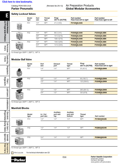
Thread type
NPT
P32
1/2"
1/4"
1/2"
NPT
Part number P31MA92022N
P32MA94024N
P33
3/4"
1/4"
1/2"
NPT
P33MA96024N
Proportional Dump Valves Operators Flow Charts
For thread type: BSPP 1, BSPT 2, NPT 9 Most popular. For technical information see CD
P33
1/2"
NPT
3/4"
NPT
66.5 (141) 101.9 (216) 128.4 (272) 136.9 (290) 141.6 (300)
P32VA92LSAN P32VA93LSAN P32VA94LSAN P33VA94LSAN P33VA96LSAN
P32VA92LSBN P32VA93LSBN P32VA94LSBN P33VA94LSBN P33VA96LSBN
Part number P33KA00MR
P33KA00ML
P32 Series Accessories
Description Angle bracket (Fits to regulator and filter / regulator body)
L-bracket (Fits to filter and lubricator body)
Filters Air Preparation Products
气动元件使用说明1
气动元件使用说明气压传动系统中,气源处理件是指空气过滤器、减压阀和油雾器,有些品牌的电磁阀和气缸能够实现无油润滑(靠润滑脂实现润滑功能),便不需要使用油雾器!过滤度一般为50-75μm,调压范围为0.5-10Mpa,如需过滤精度为5-10μm,10-20μm,25-40μm,及调压为0.05-0.3Mpa,0.05-1Mpa三大件无管连接而成的组件称为三联件。
三大件是多数气动系统中不可缺少的气源装置,安装在用气设备近处,是压缩空气质量的最后保证。
三大件的安装顺序依进气方向分别为空气过滤器、减压阀和油雾器。
空气过滤器和减压阀组合在一起可以称为气动二联件。
还可以将空气过滤器和减压阀集装在一起,便成为过滤减压阀(功能与空气过滤器和减压阀结合起来使用一样)。
有些场合不能允许压缩空气中存在油雾,则需要使用油雾分离器将压缩空气中的油雾过滤掉。
总之,这几个元件可以根据需要进行选择,并可以将他们组合起来使用。
空气过滤器用于对气源的清洁,可过滤压缩空气中的水分,避免水分随气体进入装置。
减压阀可对气源进行稳压,使气源处于恒定状态,可减小因气源气压突变时对阀门或执行器等硬件的损伤。
过滤器用于对气源的清洁,可过滤压缩空气中的水份,避免水份随气体进入装置。
油雾器可对机体运动部件进行润滑,可以对不方便加润滑油的部件进行润滑,大大延长机体的使用寿命。
安装:气源处理件使用说明:1、过滤器排水有压差排水与手动排水二种方式。
手动排水时当水位达到滤芯下方水平之前必须排出。
2、压力调节时,在转动旋钮前请先拉起再旋转,压下旋转钮为定位。
旋转钮向右为调高出口压力,向左旋转为调低出口压力。
调节压力时应逐步均匀地调至所需压力值,不应一步调节到位。
3、给油器的使用方法:给油器使用JIS K2213输机油(ISO Vg32或同级用油)。
加油量请不要超过杯子八分满。
数字0为油量最小,9为油量最大。
自9-0位置不能旋转,须顺时针旋气源处理件:气源处理件包括过滤器、减压阀、过滤减压阀、油雾器以及它们组成的二联件、三联件。
Parker Pneumatic 环保空气节约设备说明说明书

Air Saver UnitAn environmentally friendly solution to reducing air consumption.Contents PageFeatures ..................................................................................................... 3-4Specifi cations ................................................................................................ 5Dimensions - ASV-200-AA-M5 ...................................................................... 6Dimensions - ASV-2000-AA ........................................................................... 7Dimensions - ASV-5000-AA ........................................................................... 8Dimensions - ASV-13000-AA .......................................................................... 9Dimensions - ASV-15000-AA ........................................................................ 10Dimensions - ASC500-1W / ASO500-1W ..................................................... 11Applications ............................................................................................. 12-13Selection of Air Saver Unit ........................................................................... 14Other Parker Energy Saving Products (15)For more information and videos visit: /pneu/airsaverImportant !Before carrying out any service work, ensure that the Air Saver Unit has been vented.Remove the primary supply air hose to ensure total disconnection of the air supply before dismantling valves or blank connection blocks.NB !All technical data in this catalog is typical only.The air quality is decisive for the valve life:see ISO 8573.WARNING FAILURE OR IMPROPER SELECTION OR IMPROPER USE OF T HE PRODUCTS AND/OR SYSTEMS DESCRIBED HEREINOR RELATED ITEMS CAN CAUSE DEA TH, PERSONAL INJURY AND PROPERTY DAMAGE.This document and other information from Parker Hannifi n Corporation, its subsidiaries and authorized distributors provide product and/or system options for further investigation by users having technical expertise. It is important that you analyze all aspects of your application including consequences of any failure, and review the information concerning the product or system in the current product catalog. Due to the variety of operating conditions and applications for these products or systems, the user, through its own analysis and testing, is solely responsible for making the fi nal selection of the products and systems and assuring that all performance, safety and warning requirements of the application are met.The products described herein, including without limitation, product features, specifi cations, designs, availability and pricing, are subject to change by Parker Hannifi n Corporation and its subsidiaries at any time without notice.Offer of SaleThe items described in this document are available for sale by Parker Hannifi n Corporation, its subsidiaries or its authorized distributors. Any sale contract entered into by Parker will be governed by the provisions stated in Parker’s standard terms and conditions of sale (copy available upon request).© Copyright 2016 Parker Hannifi n Corporation. All Rights Reserved!!!An easy solution to your environmental protection efforts!The Air Saver Unit contributes to power savings and CO 2 reduction.ASV2000 Series ASV5000 SeriesWhen using an Air Saver Unit several significant benefits can be achieved. Air blowing accounts for almost 50% of all compressed air used in plants. By using switching valve technology the Air Saver Unit can reduce air consumption by up to 50%!ASV200 SeriesASC/ASO500 Series • Large reductions in air consumption.• Savings in compressor power consumption.• Reduction in plant CO 2 emissions.• Big contribution to energy-saving activities.• Improved effi ciency.VALUE IMPACT SUMMARYReduced Total Annual Air Discharge Per Blowing Nozzle (scfm) by:3,232,005Reduced Annual CO2 Emissions Generated (Per Blowing Nozzle - in Tons) by: 5.77 tons Reduced Annual Air Generating Costs Per Blowing Nozzle by:$ 892.03Quantity of Air Blowing Nozzles With Same Application Specifications 4Reduced Annual Air Generating Costs For All Nozzles by:$ 3,568.13Reduced Annual CO 2 Emissions Generated (For All Blowing Nozzles) by:23.07there is no air consumption.Energy/cost savingTry our fast and easy online savings calculator! /airsaverSampleApplication4nozzels 6mm dia.$0.10 / kWh1 min blow per 4 min cycle3 shifts 5 days /weekPrepared forPrepared byAir Saver Unit Valve CalculatorSummary Sheet✶ To achieve the benefi ts of pulsed air, the Air Saver Unit should be installed no more than 3 meters away from the air blow orifi ce. For optimal results install within 1 meter.Installation is simple and reduction in air consumption can be realized immediately.• W hen using an electrically operated solenoid valve to control the air blow, an Air Saver Unitcan quickly and easily be retrofi tted providing an immediate reduction in air consumption withno changes to the PLC program.Before introduction of the unit Before introduction of the unit After introduction of the unit• Easy to install. Change the current solenoid valve to Air Saver Unit. (ASC500 or ASO500)• Program change of controller is not necessary.• W hen using manual valves such as ball valves, simply install either ASV200, ASV500 orASV2000 units which do not need electrical power. Installing the unit brings immediate reduction in air consumption and improved compressor efficiency.[Company A] Food & Beverage manufacturer“When we tested ASV5000, we achieved about 55% reduction of our air consumption. Because air blow effi ciency was improved, we plan to use more Air Saver Units in other areas in the plant”.[Company B] Manufacturer of offi ce document machines “We are working on energy-saving activities. In those activities,we decided to use an Air Saver Unit. We have more than 100points of air blow and we reduced our air consumption by 42% using this unit”.ts of ce. For optimal To achieve the benefi ts ofpulsed air, install no more than 3 meters away from the air blow orifi ce. For optimal results install within 1 meter.Specifi cationParker PneumaticSpecifi cationsASV200ASV2000ASV5000ASV13000ASC500ASO500Normally closedNon lubricated air459.1Notes:* External pilot of 43.5 - 116 is required, to ensure proper operation.†For maximum life of the unit we recommend 5 micron, but 40 micron fi ltration is acceptable and will not void warranty.To achieve the benefi ts of pulsed air, the Air Saver Unit should be installed no more than 3 meters away from the air blow orifi ce. For optimal results install within 1 meter.Parker PneumaticPipingPort 1: Supply port (Compressor side)Port 2: Output port (Blow nozzle side)Port 3: Exhaust port** In order to keep out dust, the air muffl er is recommended for exhaust port.ASV200-AA-M5Ordering Information ASV200-AA-M5Flow @ Port Operating Pressure Pilot air Dimensions: ASV200-AA-M5Notes:A. When temperature of valve goes below 5°C (41°F), complete dry air shall be supplied to prevent from freezing.B. Air Saver Units with WP prefix are suitable for mostpainting applications. Test before use if in direct contact with painted surface.C. If test in painting application fails, try cycling Air Saver Unit for 48 hours and repeat test.D. DO NOT use “WP” Air Saver Unit in ‘clear coat’ applications.E. Adjustable to maximum frequency of 5Hz.Port 2 - 3/8 PluggedPort 4 - 3/8Pilot air supply port M5Mounting holeOFF timeadjustment needle ON timeadjustment needlePort R2 - 3/8 PluggedThreshold elementPort 3 -3/8 pluggedPort 1 - 3/8 supply3 x ø 0.280.980.981.181.181.893.192.541.180.590.79Max 0.610.202.132.683.230.040.59PipingPort 1: Supply port (Compressor side)Port 2: PluggedPort 3: PluggedPort 4: Output port (Blow nozzle side)Port R2: PluggedPort X: M5 pilot air supply>43.5 psi is requiredOrdering Information ASV2000-AA-xxFlow @ Port Operating Pressure Pilot air PortDimensions: ASV2000-AA-97 (NPT model)Notes:A. When temperature of valve goes below 5°C (41°F), complete dry air shall be supplied to prevent from freezing.B. Air Saver Units with WP prefix are suitable for most painting applications. Test before use if in direct contact with painted surface.C. If test in painting application fails, try cycling Air Saver Unit for 48 hours and repeat test.D. DO NOT use “WP” Air Saver Unit in ‘clear coat’ applications.E. Adjustable to maximum frequency of 5Hz.(E)PipingPort 1: Supply port (Compressor side)Port 2: Plugged Port 3: PluggedPort 4: Output port (Blow nozzle side)Port 5: PluggedPort X: M5 pilot air supply >43.5 psi is requiredOFF timeOrdering Information ASV5000-AA-xxFlow @ Port Operating Pressure Pilot air Port Dimensions: ASV5000-AA-91 (NPT model)(E)Notes:A. When temperature of valve goes below 5°C (41°F), complete dry air shall be supplied to prevent from freezing.B. Air Saver Units with WP prefix are suitable for most painting applications. Test before use if in direct contact with painted surface.C. If test in painting application fails, try cycling Air Saver Unit for 48 hours and repeat test.D. DO NOT use “WP” Air Saver Unit in ‘clear coat’ applications.E. Adjustable to maximum frequency of 5Hz.PipingPort 1: Supply port (Compressor side)Port 2: Output port (Blow nozzle side)Port 3: PluggedPort X: 1/8 NPT pilot air supply >43.5 psi is requiredONX PortPilot air port 1/8 NPTOFF timeadjustment needle ON timeadjustment needle4 x ø 0.43(Mounting hole)1A33.863.034.412OFF 2.321.633.720.355.164.653.940.678.272.682.322.010.310.790.791.165.87Port 1, 2, 3 (3 x 1 NPT)AOrdering Information ASV13000-AA-xxFlow @ Port Operating Pressure Pilot air Blow PortDimensions: ASV13000-AA-94 (NPT model)(E)Notes:A. When temperature of valve goes below 5°C (41°F), complete dry air shall be supplied to prevent from freezing.B. Air Saver Units with WP prefix are suitable for most painting applications. Test before use if in direct contact with painted surface.C. If test in painting application fails, try cycling Air Saver Unit for 48 hours and repeat test.D. DO NOT use “WP” Air Saver Unit in ‘clear coat’ applicationsE. Adjustable to maximum frequency of 1Hz.PipingPort 1: Supply port (Compressor side)Port 2: Plug (1-1/4) Port 3: Plug (1-1/4)Port 4: Output port (Blow nozzle side)Port 5: Plug (1-1/4)Port X: 1/8 NPT pilot air supply >43.5 psi is requiredONPort 4 -1-1/4 NPTOFF timeadjustment needleON timeadjustment needle4 x ø 0.43 (Mounting hole)Port 1 -1-1/4 NPT0.792.288.03OFF 4.210.432.403.665.676.61X PortPilot Air supply 1/8 NPT2.952.28Port 2Plug8.981.141.14Port 3PlugPort 5Plug 3.905.671.180.982.28Ordering Information ASV15000-AA-xxFlow @ Port Operating Pressure Pilot air Port Dimensions: ASV15000-AA-92 (NPT model)(E)Notes:A. When temperature of valve goes below 5°C (41°F), complete dry air shall be supplied to prevent from freezing.B. Air Saver Units with WP prefix are suitable for most painting applications. Test before use if in direct contact with painted surface.C. If test in painting application fails, try cycling Air Saver Unit for 48 hours and repeat test.D. DO NOT use “WP” Air Saver Unit in ‘clear coat’ applications.E. Adjustable to maximum frequency of 1Hz.Parker PneumaticPipingPort 1: Supply port (Compressor side)Port 2: Output port (Blow nozzle side)Y port: Pilot exhaust port** In order to avoid dust, it is recommended to attach an air muffl er.ASC500-1W / ASO500-1WOrdering Information ASC500-1W / ASO500-1WFlow @ Port Operating Pressure Pilot air Dimensions: ASC500-1W-90 / ASO500-1W-90 (NPT model)Port 21/8 NPTASC Version OnlyASO Version Only 2 x Ø7.57.51515Wiring Specifications1: Continuous blow ON (−)15.5Port Y: M5ASC OnlyPort 11/8 NPTPort Y: M5ASO Only7.57.515.5(B)Notes:A. When temperature of valve goes below 5°C(41°F), complete dry air shall be supplied to prevent from freezing.B. Adjustable to maximum frequency of 22Hz.Cleaning blow before assemblySwarf removalAssist blow for PET bottle transferLiquid removal after the manufacturing processCan be used in many applications where air blow is a requirementDrying ApplicationsSwarf RemovalCooling ApplicationIonizer Dust RemovalPET Bottle TransferCar PaintingProcessPaint spraying *Electrical parts* Air Saver Units with WP prefi x are suitable for most painting applications. Test before use if in direct contact with painted surface. If test in painting application fails, try cycling Air Saver Unit for 48 hours and repeat test. DO NOT use “WP” Air Saver Unit in ‘clear coat’ applications.Air Saver UnitPneumatic Solutions for Beverage and Bottle Plants molded PET bottles.Escape blow for PET bottles when the line is stopped.date on them.Selection of Air Saver UnitGuide data for the correct selection of an Air Saver Unit for blow applications.Please take into account the two variables:• System operation pressure (PSI)• Required air consumption of nozzle or set of nozzles (scfm) to be controlled with one Air Saver Unit Color coding indicates correct Air Saver UnitReduced performance flow capacity of 10% is applied Consider min. operating pressure (see tech specs on page 5)Consider min. pilot air pressure (see tech specs on page 5)Nozzle area (mm2)0.00.00.10.20.81.83.17.112.619.628.335.850.263.678.595.0113.0132.7153.9176.6201.0226.9254.3283.4314.0346.2379.9415.3452.2490.6ASV200ASC500/ASO500ASV2000ASV5000ASV13000ASV15000Other ParkerEnergy Saving Productsand Tools PortfolioWear CompensatedSeals• Air valve spools that havewear compensation• Air pressure forces the sealsout to the valve bore.• Very little air leakage acrossthese spools through outit’s life.• Especially better than lappedspool valves.Pressure DifferentialSensors• Monitor pressure dropon fi lters.• Provide electrical signalsor visual indicators whenpressure drop is high andfi lter elements need replaced.• Can assist you in loweringcompressed air costs byreducing pressure drops.Straight Fittings,Pre-Sealed• Factory applied threadsealant perform better thanoperator applied sealant.• Where ever possible,use straight fi ttings inplace of 45 or 90 degreeelbow fi ttings to minimizepressure drop and save oncompressed air costs.Zero Loss Air Drains• Many Compressors and AirTanks use Timer Drains topurge water and moisturefrom the tanks.• Timer Drains wastecompressed air becausethey blow too long, and blowwhen no water is present.• Zero Loss Drains use fl oatsto actuate the drain to openand blow out moisture andshut off once moisture isgone, saving compressedair costs.Pneumatic Sizing Tools• Air Cost, Flow, and ProductSizing Calculators• Conversion tools (e.g.Pressure BAR to PSI)• Available on website,downloadable for cellphones and I Pads fromApple App Store.Air EconomizingVacuum Generators• Built-in sensors onlyapply air pressure whenvacuum is needed.• Sensor turns generatoron when vacuum dropsto a preset level.• Reduces plantcompressed air costs.Low Power Solenoids• Typical Class 8 22mmCoil Wattage 5.4W• Parker 15mm CoilWattage 1.2W• Save 4.2W whiledoing workReverse Flow Regulators• Most actuators only needwork force in one direction.• Installed between valveand actuator.• Reduces pressure on thereturn stroke of an actuatorwhere work force is notneeded.• Reduces plant compressedair costs.Catalog 0698P 06/2016Applications EngineeringPhone: 877 321 4PDN Option #2E-mail:******************Customer SupportPhone: 877 321 4PDN Option #1Parker Hannifi n Corporation Pneumatic Division 8676 E. M89P .O. Box 901Richland, MI 49083 USA。
安装与使用-AirTAC

安装与使用
1、安装方式:
2、负载大小的确定:
气缸负载大小由理论保持力(理论推力)决定,为确保气缸的正常使用,负载大小不可超过下表规定的气缸理论保持力(理论推力);
3、油压缓冲器的配置:
3.1、油压缓冲器属于易耗品,当能量吸收能力下降时应及时更换,下表为各缸径气缸所配油压缓冲器型号对照表,您只需根据下表要求订购相应规格的油压缓冲器再按下图所示步骤更换掉旧的油压缓冲器。
3.2、油压缓冲器尾部螺孔并非调节之用,随意调节会造成油品泄漏;
3.3、请用下表规定的锁紧力矩锁紧油压缓冲器锁紧螺母。
4、感应开关的配置:
只有附磁型气缸才可配置感应开关。
附磁型气缸磁石配置在本体四角内,具体位置如下图。
附磁型气缸附有感应开关安装架,且在左右固定板上有两组安装架固定孔。
选择本公司的CS1-G、CS1-GX、DS1-G、DS1-GN、DS1-GP型号的感应开关然后将其导入安装架沟槽
并调整至适当位置后拧紧紧定螺丝即可。
注:感应开关的具体更详细资料请参考样本。
气源处理单元安全操作及保养规程
气源处理单元安全操作及保养规程气源处理单元是工业生产中常用的设备。
为了保证气源处理单元的安全可靠运行,避免事故发生,我们需要深入了解气源处理单元的安全操作和保养规程。
安全操作规程环境安全气源处理单元应安装在干燥、通风良好、无积水、无腐蚀性气体的环境中。
作业现场应保持整洁、无杂物,入口不应堵塞。
操作规程操作前应做好检查,检查重要部件有无异常,比如压力表、润滑杯、液位计等。
操作时一定要按照流程操作,并注意以下几点:正确接线连接气源处理单元的进出口气管前,应检查气管有无扭曲、损坏、老化等情况,并确保连接口无松动。
接线时应按照气管上的标识进行,严禁接错。
正确操作开机前应检查所有操作件是否处于关闭状态,包括阀门、旋钮及面板上的装置。
开机时要从小到大逐渐增加气压,防止因气压突然增大导致设备故障。
关闭设备前应逐步降低压力至零后再执行关闭操作。
定期检查进行定期检查时,应停机操作,按厂家提供的保养手册进行检查,发现异常情况应及时修复。
保养周期一般建议是1个月/次。
安全措施光电、声光、断路器控制安装光电、声光、断路器等保护设备,确保当设备发生故障时能够及时停机。
操作限制加强对气源处理单元的操作限制,由专人进行操作,防止非专业人员乱操作。
安全警示标志在设备周边设置警示标志,提高工作人员的安全意识。
保养规程定期清洗在使用一段时间后,应进行清洗保养,最好每一年进行一次,清洗过程应该采用专业清洗液和方法。
清洗时不要直接使用水龙头冲洗设备内部,可能会导致设备故障。
定期检查进行定期检查时,应关注以下事项:电气部分检查检查电气部分有无失效、老化等情况,是否还能正常工作。
润滑部分检查使用设备时应注意润滑部分有无干涩,润滑油是否需要添加。
规范使用操作合理使用压力表,不能超过设定压力上限,同时减少反复升降压操作,降低设备的磨损程度。
定期更换零配件当检查出设备出现故障或部分零配件老化失效时,应及时更换,避免事故的发生。
总结气源处理单元是一种常见设备,确保其安全可靠运行对于工业生产的顺利开展至关重要。
Millipore M Air T 压缩气体和空气采样套件用户指南说明书

M Air T®Compressed Gas and AirSampling KitUser GuideNoticeThe information in this document is subject to change without notice and should not be construed as a commitment by Millipore Corporation. Millipore Corporation assumes no responsibility for any errors that may appear in this document. This manual is believed to be complete and accurate at the time of publication. In no event shall Millipore Corporation be liable for incidental or consequential damages in connection with or arising from the use of this manual.Copyright 2002, Millipore Corporation. All rights reserved. This book or parts thereof may not be reproduced in any form without the written permission of the publishers. Printed in U.S.A.Millipore and M Air T are registered trademarks of Millipore Corporation.Tri-Clover is a registered trademark of Alfa Laval, Inc.P36483, Rev. –, 10/02IntroductionThe new M Air T® Compressed Gas and Air Sampling Kit is designed especially to monitor the microbiological quality of compressed gas and air used in the pharmaceutical and food & beverage industries. Connected to the M Air T Isolator Pump ATBPUMP01, the new sampling kit allows accurate sampling and microbiological monitoring of a compressed gas sample, by direct impaction onto the M Air T pre-filled agar cassette.The pre-sterilized M Air T agar cassettes used with the M Air T Compressed Gas and Air Sampling Kit are easier to handle, especially when wearing gloves, significantly reducing the risk of inadvertent contamination. The M Air T Compressed Gas and Air Sampling Kit is manufactured from stainless steel, with sanitary Tri-Clover®connections, making it autoclavable.The design of the M Air T Compressed Gas and Air Sampling Kit allows one to sample compressed gas or air up to 5 bar (73 psi) of pressure, without any pressure reducer.ApplicationsThe M Air T Compressed Gas and Air Sampling Kit, connected to the M Air T Isolator Pump, is suited for a variety of applications, as fol-lows.Pharmaceutical■Evaluation of the microbiological quality of compressed gas or air used for blanketing, purging, sparging or stirring products■Evaluation of the microbiological quality of confined areas such as Blow Fill Seal (BFS) sterile showersFood and Beverage■Evaluation of the microbiological quality of compressed gas or air used for blanketing, purging, cooling and freezing productsComponent DiagramItem Description FunctionA Pressure reducer Connected to the sampling port, to reduceincoming pressureB Clamp, 1.5 in. TC To connect pressure reducer to cone adapterC Cone adapter To reduce charge loss and to expand impactiononto the entire agar surfaceD Clamp, 4 in. TC To connect cone adapter to impaction sieveE Impaction sieve Captures microorganisms using 611 micro-perforationsPrecautions/Limitations■Autoclave all parts at 121 °C for 20 minutes before any compressed gas or air sampling.■Use only with the M Air T Isolator Pump.■Use only M Air T cassettes with this unit..■Do not use for microbiological monitoring of compressed O2■Do not sample gas or air at pressures above the specified limit of5 bar (73 psi).M Air T Sampling Kit User Guide3 Assembling the M Air TCompressed Gas and Air Sampling Kit1.With the 1.5-inch TC clamp, connect the valve to the cone adapter.Installing the M Air T CassetteThe M Air T cassette, in its gamma-irradiated double-sleeve packaging, has been qualified and validated to monitor up to 1000 liters of com-pressed gas or air.1.Grasp the wings of the cassette and place it on the sampling head.Lock the cassette into place.2.Remove the cover and place it on a work surface with the insidefacing down.M Air T Sampling Kit User Guide5 3.Place the sieve, cone adapter and pressure reducer on the cassetteand lock it into position.4.As described in detail in the M Air T Isolator Pump User Guide,connect the assembly to the pump, using the components supplied with the pump:a.Install the assembly on the tripod.b.Connect the assembly to the pump, using the silicone tubing.Installing the M Air T Cassette, continued5.Connect the compressed gas sampling port to the inlet connectionof the pressure reducer.6.Open the sampling valve and adjust the valve indicator to between5 and6 mm, to achieve an inlet gas flow rate between 140 and180 liters/minute.Note:If the sampling port does not allow this flow rate to be achieved, a flow rate adjustment valve can be placedbetween the sampling port and the pressure reducer.CAUTION:During sampling, the inlet gas flow rate must exceedthe vacuum flow rate (136 liters/minute), so that theexcess air will be diverted through the evacuationholes to the pressure reducer.7.After sampling, close the sampling port. Loosen the sieveconnected to the cone adapter, remove it and replace the cassette cover.M Air T Sampling Kit User Guide7 8.Remove the cassette by grasping the “wings” and lifting it off thesampling head.bel the cassette.NOTE: Incubate the cassette upside down.SpecificationsDimensions (M Air T Compressed Air/Gas Sampling Kit): Total height:310 mm (12.2 in.)Total width:170 mm × 130 mm(6.7 in. × 5.11 in.)Total weight: 3.5 kgMaximum operating pressure: 5 bar (73 psi)Materials of ConstructionPressure reducer, cone adapter,sieve and clamps:316 AISI stainless steelGaskets siliconeProduct Ordering InformationThis section lists the catalogue numbers for the M Air T Compressed Gas and Air Sampling Kit. See the Technical Assistance section for information about contacting Millipore. You can also buy Millipore products on-line at /purecommerce. Description Qty/Pk Catalogue No. M Air T Compressed Gas and AirSampling Kit1ATBH GAS 01 The kit includes the following:M Air T pressure reducer1ATBH PRE 01M Air T cone adapter1ATBH C0N 01 M Air T sieve for cone adapter1ATBC SEV 01 Clamp, 1.5 in. TC1YY20 040 45 Clamp, 4 in. TC1FTPF 007 88 Silicone gasket, 1.5 in. TC10YY20 040 55 Silicone gasket, 4 in. TC10FTPF 007 89 Flow Rate Adjustment Valve (Optional)Valve, 3/4 in. TC1YFS7ETC34 Female Plug, 3/4 in. TC1YFS714N34 Silicone seal, 3/4 in. TC10YFS7S0034 Clamp, 3/4 in. TC1YFS7TCC34M Air T Isolator Pump and AccessoriesM Air T isolator pump1ATBP UMP 01M Air T isolator tripod1ATBF EET 01M Air T isolator sampling head1ATBH EAD 01M Air T isolator printer1ATBP RNT 01M Air T isolator tubing1ATBT UBE 01M Air T Agar CassettesPre-filled gamma-sterilized in double sleeves (6 bags with 4 or 10 cassettes each) Medium Application Qty/Pk Catalogue No. Tryptic Soy Total count60ATSM TTD 60 Sab Dex Yeast and mold60ATSM SDD 60 TSA w/ beta lactamase Areas containing antibiotics60ATSM PND 60 Tryptic Soy Isolator monitoring24ATSM TTB 24 TSA w/pyruvate Isolator monitoring24ATSM TPB 24(VHP-sanitized)M Air T Sampling Kit User Guide9Technical AssistanceFor more information, contact the Millipore office nearest you. In the U.S., call 1-800-MILLIPORE (1-800-645-5476). Outside the U.S., see your Millipore catalogue for the phone number of the office nearest you or go to our web site at /offices for up-to-date worldwide contact information. You can also visit the tech service page on our web site at /techservice. Standard WarrantyMillipore Corporation (“Millipore”) warrants its products will meet their applicable published specifications when used in accordance with their applicable instructions for a period of one year from shipment of the products. MILLIPORE MAKES NO OTHER WARRANTY, EXPRESSED OR IMPLIED. THERE IS NO WARRANTY OF MERCHANTABILITY OR FITNESS FOR A PARTICULAR PURPOSE. The warranty provided herein and the data, specifications and descriptions of Millipore products appearing in Millipore’s published catalogues and product literature may not be altered except by express written agreement signed by an officer of Millipore. Representations, oral or written, which are inconsistent with this warranty or such publications are not authorized and if given, should not be relied upon.In the event of a breach of the foregoing warranty, Millipore’s sole obligation shall be to repair or replace, at its option, the applicable product or part thereof, provided the customer notifies Millipore promptly of any such breach. If after exercising reasonable efforts, Millipore is unable to repair or replace the product or part, then Millipore shall refund to the customer all monies paid for such applicable product or part. MILLIPORE SHALL NOT BE LIABLE FOR CONSEQUENTIAL, INCIDENTAL, SPECIAL OR ANY OTHER INDIRECT DAMAGES RESULTING FROM ECONOMIC LOSS OR PROPERTY DAMAGE SUSTAINED BY ANY CUSTOMER FROM THE USE OF ITS PRODUCTS.P36483, Rev. –, 10/02。
气源处理元件(二联件)执行标准
气源处理元件(二联件)执行标准气源处理元件是指对来自气源的气体进行净化、过滤、调压、调节、计量等处理的元件。
它们通常用于工业自动化控制系统中,用来保证气动执行元件的正常工作,提高系统的稳定性和可靠性。
气源处理元件的执行标准主要包括两方面:国际标准和行业标准。
国际标准是指在全球范围内广泛适用的标准,用于规定气源处理元件的技术要求、性能指标、测试方法等。
主要的国际标准有ISO标准和EN标准。
ISO标准是国际标准化组织制定的全球通用标准。
ISO 6953《气源处理元件触发时间减到控制介质的快速停用》是气源处理元件的执行标准之一。
该标准规定了气源处理元件触发时间的要求,即气源处理元件在停用时,控制介质的流向应迅速停止。
该标准的执行对于保证气动执行元件的正常工作和系统的安全运行具有重要意义。
EN标准是欧洲标准化委员会制定的欧洲地区适用的标准。
EN 12286《气源处理元件试验方法》是气源处理元件执行标准之一。
该标准规定了气源处理元件的试验方法,包括气体流量测量、气泡测试、密封性能测试等。
该标准的执行对于保证气源处理元件的质量和性能具有重要意义。
除了国际标准外,行业标准也是指导气源处理元件设计、制造和使用的重要依据。
行业标准主要由国内相关的行业协会或机构制定,根据某个特定领域的需求和特点,针对气源处理元件的技术要求、性能指标等进行规定。
行业标准通常与国际标准相衔接,相互参照,形成一个完整的标准体系。
总结起来,气源处理元件的执行标准包括国际标准和行业标准两部分内容。
国际标准主要包括ISO标准和EN标准,用于规定气源处理元件的技术要求、性能指标、测试方法等。
行业标准主要由国内相关的行业协会或机构制定,根据特定领域需求和特点进行规定。
执行标准对于保证气源处理元件的质量、性能和安全具有重要意义。
百灵气动AirTAC型气源处理件说明书
百灵气动AirTAC型气源处理件说明书一.使用条件(技术参数)气源处理件使用的系统压力,介质温度及调压范围应符合下表规定的数值:最高使用压力 1.0Mpa(10.2kgf/㎝2)环境及流体温度5~60建议用油透平1号油(ISOVG32)滤芯精度40u调压范围0.05~0.85Mpa(0.51~8.7kgf/㎝2)工作介质空气杯防护罩1000~2000无2500~6000有阀型带溢流型二.安装使用1.安装应注意清洗连接管道与接头,避免将脏物带入气路。
2.安装应注意气流方向与本体上的箭头方向一致,注意接管及牙型是否正确。
3.压力调节:将调压旋钮向上拉起,顺时针旋转,压力上升。
逆时针旋转,压力下降。
调整至所需压力,将调压旋钮按下呈锁紧状态.4.水分排出:无空气压力时,水分自动排出。
有空气压力时,将排水柱向上推,水分排出,排水完毕,将排水柱放开,排水柱自动弹下,排水结束。
当水位超过上限时,请及时排水,否则将造成除湿不良。
5.油量调整:旋转调油旋盖,将旋盖上数字对准▲箭头方向:数字0为油量最小,9为油量最大。
自9到0位置不能逆时针旋转,需顺时针旋转。
设定数字后,空气流量大,滴油量大,空气流量小,滴油量小。
(顺时针旋转针阀,滴油量减少;逆时针旋转针阀,滴油量增加。
空气量调整,设定针阀后空气流量大,滴油量大,空气流量小,滴油量小。
)6.加油方法;可以不关闭空气管路而进行加油作业,逆时针旋起加油螺丝,加油时加油量不用超过杯子80%.加完油后,将加油螺丝锁紧;不可直接将油杯卸下进行加油。
三.保养1。
清洗/更换滤网:取出滤网,用空气由内向外吹,即可以重复使用。
2.透明PC杯:卸下PC杯,用干净干布擦拭即可,不可使用任何会破坏PC杯材质的化学物品来清洗。
四.使用注意事项1.使用压力请勿超过1Mpa.2.禁止接近或在有机溶剂环境中使用3.给油雾器油杯中加油时,要关闭进入油雾器的压缩空气4.其他详细资料参产品样本五.定购代码示例1. AC------2000-------M↓↓↓型号接管口径排水方式AC:A系列三联件1500:PT1/8 空白:差压排水式AFC:A系列二联件2000:PT1/4 M:标准手排式2. AC2000-----------------01↓↓型号接管口径/螺纹(Rc)AC三联组合M5--M5AF过滤器01---1/8:Aw调压过滤器02---1/4AR调压阀03---3/8AL油雾器04---1/206---3/410---1。
气动压接机说明书
立式气动压接机使用说明书一、产品介绍1.以0.2-1MPA的压缩空气为动力源,低噪音,无污染,操作简便.外接AC220V交流电源.总耗电功率不超过20W.2.机械启动方式采用双按钮开关(或脚踏开关)设计.3.气缸下行速度可调,气缸行程可调,也可按客户要求定做。
4.只需调整气压调压阀.就可达到所需要的压装力,简单方便。
5.单柱型左右前三面开放式设计,轻巧不占空间,.结构简单,极少维修,生产效率高;6.可另增加发热模具及智慧温控仪,适用于热压成型、烙印、压凸等工艺7.具有自动计数,压装时间设定功能..8.产品参数:动力类型:气动公称压力:200(kg)工作台尺寸:450mm*450mm气缸规格:100mm*200mm 可调行程:100mm二、试机1、将压机固定在工作台上,然后装上需要使用的模具。
2、接上气源,打开压机二连件上的推拉开关,可调节模具的吻合位置。
(调节时,可用压机电磁阀上的手动调节按钮)。
3、插上交流电源AC220V,电源插头自动变压为直流DC24V,输入控制箱,将二连上的减压阀“压力调节”调至试用压力(5kg以下)。
此时,压机上模会上升至上止点(此设计主要是为了工作人员的安全)。
4、打开控制箱电源开关,按下手动开关即可看到电源指示灯和计数器灯亮。
按下脚踏开关上模就会下降,等气缸完全下降,就可知道微调的大概行程,然后调节行程,往返几次,就可调好上、下模的吻合位置。
5、接下来是将工件放在模具上试压,如压力太小,可调二联件上的减压阀,(顺时针为增加压力,逆时针为减小压力)直到调节到理想的压力,再将减压阀上的调节部位往下压(即可锁上)。
三、行程调节1、将立柱的上板后两个锁紧螺丝松开,将中间螺丝紧上,直至上支撑板能转动为止。
然后转动手轮,上下行程即可任意调节。
四、压力调节将调压器上端轻轻往上拉,按顺时针可将压力调大,顺时针则相反,调节至压力认为满意为止,并将其锁紧,以免压力变动。
操作简单,方便。
不锈钢气源处理单元滤器系统说明书
不锈钢气源处理单元气源处理单元不锈钢警告,销售条件!ᅠ ᅠ警告本样本所述的产品和/或系统出现故障或选择不当或使用不当或相关物品可能导致死亡、人身伤害和财产损失。
本文件及其他信息由派克汉尼汾公司、其子公司及授权分销商提供产品和/或系统选项,供具有技术专长的用户进一步研究。
重要的是要分析一切你的应用场合的各个方面,包括任何失败的后果,并检查在当前产品样本有关产品或系统的信息。
由于这些产品或系统的操作条件和应用的多样性用户通过自己的分析和测试,全权负责产品和系统的最终选择能够满足应用场合的所有性能、安全和警告要求。
本样本中所述的产品,包括但不限于产品特性、规格、设计、可用性和价格,如有更改,派克汉尼汾公司及其附属公司可随时更改,恕不另行通知。
销售条件本样本中的产品由派克汉尼汾及分支机构,及授权经销商销售。
所有派克输入的销售合同,将遵守派克的销售标准条款。
(可提供复印件)内容气源处理单元不锈钢产品选型表 (1)空气过滤器微型PF504 .................................................................................................................................................2-3 标准型PF10 ..............................................................................................................................................4-5空气聚结式过滤器微型PF501 .................................................................................................................................................6-7 标准型PF11 ..............................................................................................................................................8-9空气减压阀微型PR354, PR364 ...............................................................................................................................10-11 标准型PR10, PR11 ...............................................................................................................................12-13空气过滤 / 减压阀微型PB548, PB558 ...............................................................................................................................14-15 标准型PB11, PB12 ...............................................................................................................................16-17 标准不锈钢过滤调压阀-主推产品....................................................................................................18-19油雾器标准型PL10 ...........................................................................................................................................20-21系列接口调压范围PSIG 页1/41/22560125250减压阀PR354X –标准标准标准—10-11PR364X –标准标准标准—PR10–X —标准标准可选12-13PR11–X—标准标准可选系列接口杯子杯子容量过滤精度(微米)调压范围PSIG 页1/41/2520402560125250过滤器/减压阀PB548X–316不锈钢 1 oz.可选标准—可选可选标准—14-15PB558X –316不锈钢1 oz.可选标准—可选 可选 标准—PB11–X 316不锈钢 4 oz.可选—标准—可选标准可选16-19PB12X X 316不锈钢 4 oz.可选—标准—可选标准可选油雾器PL10–X316不锈钢4 oz.20-21产品选型表基本单元系列接口杯子杯子容量过滤精度(微米)页1/41/252040过滤器PF504X–316不锈钢 1 oz.可选标准—2-3PF10–X 316不锈钢 4 oz.可选—标准4-5聚结式过滤器PF501X –316不锈钢 1 oz..3 Micron 6-7PF11–X 316不锈钢 4 oz..3 Micron10-11Remote Auto-Fill Device微型颗粒式过滤器气源处理单元不锈钢PF504系列,1/4接口PF504颗粒式过滤器 - 微型• 不锈钢结构可应对大多数腐蚀性环境• 氟橡胶密封标准• 符合NACE规范MR-01-75/ISO 15156• 1/8"内螺纹排水•1/4"接口(NPT, BSPP)常用型号接口AutomaticDrainManual Drain微型颗粒式过滤器气源处理单元不锈钢PF504系列,1/4接口流量曲线工作原理第一级过滤:空气从入口端进入并流经导流板(A),从而引起涡旋作用。
- 1、下载文档前请自行甄别文档内容的完整性,平台不提供额外的编辑、内容补充、找答案等附加服务。
- 2、"仅部分预览"的文档,不可在线预览部分如存在完整性等问题,可反馈申请退款(可完整预览的文档不适用该条件!)。
- 3、如文档侵犯您的权益,请联系客服反馈,我们会尽快为您处理(人工客服工作时间:9:00-18:30)。
百灵气动AirTAC型气源处理件说明书
一.使用条件(技术参数)
气源处理件使用的系统压力,介质温度及调压范围应符合下表规定的数值:
最高使用压力 1.0Mpa(10.2kgf/㎝2)
环境及流体温度5~60
建议用油透平1号油(ISOVG32)
滤芯精度40u
调压范围0.05~0.85Mpa(0.51~8.7kgf/
㎝2)
工作介质空气
杯防护罩1000~2000无2500~6000有
阀型带溢流型
二.安装使用
1.安装应注意清洗连接管道与接头,避免将脏物带入气路。
2.安装应注意气流方向与本体上的箭头方向一致,注意接管及牙型是否正确。
3.压力调节:将调压旋钮向上拉起,顺时针旋转,压力上升。
逆时针旋转,压力下降。
调整至所需压力,将调压旋钮按下呈锁紧状态.
4.水分排出:无空气压力时,水分自动排出。
有空气压力时,将排水柱向上推,水分排出,排水完毕,将排水柱放开,排水柱自动弹下,排水结束。
当水位超过上限时,请及时排水,否则将造成除湿不良。
5.油量调整:旋转调油旋盖,将旋盖上数字对准▲箭头方向:数字0为油量最小,9为油量最大。
自9到0位置不能逆时针旋转,需顺时针旋转。
设定数字后,空气流量大,滴油量大,空气流量小,滴油量小。
(顺时针旋转针阀,滴油量减少;逆时针旋转针阀,滴油量增加。
空气量调整,设定针阀后空气流量大,滴油量大,空气流量小,滴油量小。
)
6.加油方法;可以不关闭空气管路而进行加油作业,逆时针旋起加油螺丝,加油时加油量不用超过杯子80%.加完油后,将加油螺丝锁紧;不可直接将油杯卸下进行加油。
三.保养
1。
清洗/更换滤网:取出滤网,用空气由内向外吹,即可以重复使用。
2.透明PC杯:卸下PC杯,用干净干布擦拭即可,不可使用任何会破坏PC杯材质的化学物品来清洗。
四.使用注意事项
1.使用压力请勿超过1Mpa.
2.禁止接近或在有机溶剂环境中使用
3.给油雾器油杯中加油时,要关闭进入油雾器的压缩空气
4.其他详细资料参产品样本
五.定购代码示例
1. AC------2000-------M
↓↓↓
型号接管口径排水方式
AC:A系列三联件1500:PT1/8 空白:差压排水式
AFC:A系列二联件2000:PT1/4 M:标准手排式
2. AC2000-----------------01
↓↓
型号接管口径/螺纹(Rc)
AC三联组合M5--M5
AF过滤器01---1/8:
Aw调压过滤器02---1/4
AR调压阀03---3/8
AL油雾器04---1/2
06---3/4
10---1。