车辆工程外文翻译
车辆工程毕业设计---英文翻译
车辆工程专业英文翻译原文:The controllable suspension system can improve both ride comfort and handling safety, which has become one research focus in the field of vehicle engineering since1950s.The full-car generally consists of four quarter-car suspension systems(QC)withstrong coupling characteristics,which yield strong coupling effects on vertical,pitch androll movement suspension performances.So far,an effective coordinated control methodfor the full-car with multiple sub-suspension systems has not been proposed.The best ideais to decouple the full-car into four independent QCs1,such that the sophisticated active orsemi-active control scheme for QC suspension can be directly employed,and thus simplifythe complicated controller synthesis for the full-car suspension and improve the real-timeproperty of control system,which has important theoretical and engineering values forrealizing the practical application of controllable suspension.This thesis focuses on the structural decoupling control study of half-car suspension,which has vertical and pitch movements.Firstly,the passive half-car dynamic model isestablished and transferred into the model involving two similar standard QC dynamicmodels.It is found that a coupling damping force exists in the sprung mass,and it can becompensated through adding a damping force in the unsprung mass, in which the half-carsuspension could be decoupled into two independent QCs.Furthermore,a new QCsuspension design with double controllable dampers is proposed on basis of the definedcoupling damping force,in which the traditional passive damper is normally replaced bythe sprung controllable dampe.Another damper named the unsprung controllable damperis installed between the lower control arm and linkage of vehicle controlled by the pitchangular acceleration,which plays role in compensating the yielded coupling damping force.Thus the suspension structural decoupling of half-car can be conveniently achieved and effectiveness of the proposed structural decoupling method of half-car suspension is verified.Finally,three kinds of control manners i.e.,active versus active,semi-activeversus active and semi-active versus semi-active,are fully discussed for the sprung and unsprung controllable dampers,respectively.The proposed active and semi-active slidingmode control schemes for the sprung controllable damper in QC are applied for thedecouplinghalf-car suspension robust control due to the uncertainty of vehicle load,andhe semi-active control manner chooses the semi-active controllable magneto-rheologicaldamper.As a result, the proposed both active versus active and semi-active versus active control manners could achieve the ideal multi-objective suspension performances for thehalf-car,and the proposed structural decoupling control method can be further extended to realize coordinated control of full-vehicle suspension system with multiple sub-suspension.Engineering vehicles working condition is usually relatively poor,coupled with thelimitations of the performance of the vehicle suspension system.It makes these vehicles' driveralways in the vibration of the high strength,and influences the driver's work efficiency,seriously hurts to the driver's spine,and directly leads to the disease.In order to reducevibration to the driver,this thesis usually takes the seat suspension system to isolate vibration,and uses the appropriate control strategies for seat suspension.It can effectively attenuate thevibration caused by uneven ground,reduce the vibration energy passed on to the driver's body,and improve the drivers'ride comfort.Magneto-rheological fluid is a kind of intelligent material,which has good rheologicalproperties.It can be the first choice of the semi-active suspension shock absorber material.According to the characteristics of magneto-rheological fluid,it can be made a lot of productswhich are used in mechanical engineering,civil engineering,etc.The most prominent exampleis magneto-rheological damper for vibration control in cable suspension bridge vibration,high-rise isolation,etc.In addition,the magnetic fluid rheostat vibration application of suspensionsystem is an important domain,including vehicle suspension system and vehicle seatsuspension system.In the suspension of the magneto-rheological damper applications,it ismainly for dissipation produced by the road excitation of vehicle and driver's vibration energy,to improve the ride comfort.Due to its good controllability,wide dynamic range,fast response,low power requirement and comparatively simple structure,magnetorheological(MR)dampers has become one of the focus research projects in automotive semi-active suspension.Besides damping force and dynamic range,the dynamic response is another important parameter of MR dampers,which isa key part of automotive MR semi-active suspension system.The dynamic response is valuable because it is one of the critical factors that determine the practical effectiveness of automotive MR dampers,the applications range of MR dampers and the controlling period directly.In this thesis,the dynamic response of automotive MR dampers is investigated and the effects of various conditions are considered.The main contributions include the following:(1)The properties and applications of MR fluid is reviewed firstly,the importance of the study on MR dampers dynamic response is discussed,and the present situation and existing problems of the study are summarized.Based on the present problems of the study,the main work is put forward.(2)Based on the hydrodynamics theory and working modes of MR dampers,applying the constitutive equations of Newton and Bingham fluid respectively,the parallel plates and annular duct based rheological equations are derived,the calculation approach of damping force is gained,and the theoretical relation between applied current,piston velocity and damping force is determined,which establishes he theoretical basis for the research of MR dampers dynamic response,propose of test approach and design of test system.Based on theoretical analysis of damping force,the calculation model of MR dampers dynamic response is built by analyzing the unstable state of MR fluid between parallel plates.Furthermore, driving by current source,the effect of the connecting way(parallel or serial)of electromagnetic coils is analyzed theoretically.(3)According to the damping force function and practical condition of dampers,an experimental approach for finding the dynamic response of automotive MR dampers and corresponding data processing are offered,the corresponding test system is developed, including some important parts of the test system,such as current driver based on PWM method,and its output characteristic and dynamic response are investigated theoretically and experimentally.译文:可控悬架系统能够同时提高车辆驾乘舒适度与操控安全性,因而具有出色的综合悬架性能,从上世纪五十年代起,就是国际车辆工程领域的研究热点课题之一。
车辆工程外文翻译--日常汽车保养
外文翻译英文:Daily car maintenance. Auto maintenance aspects should be paid attention to:(1) prevent the mixture too thick due to the high temperature, gas to flow, but also because of quantity pore expansion, gas flow rate increase, and gasoline easy to evaporation, lead to the mixture too thick. Therefore, should be the small hole, speed up adjustment device and throttle rocker connection position, reduced float chamber oil surface height, to reduce the flow of.(2) prevent air resistance the burning hot summer, the gasoline engine fuel system due to temperature happen "gas resistance" phenomenon, fuel supply shortage or even interrupted the oil supply. To prevent "gas resistance", usable asbestos gasket will gasoline pumps and exhaust pipe is separated, or with wet cloth will cover the gasoline pump cooling.(3) the evaporation under high temperature, oil and water evaporation will increase, the flap raises to cover tightly, oil pipe to prevent oil leakage; Always check the water level of water tank, the crankcase oil oil face, height, brake zongbeng inside the brake fluid liquid surface height and within the battery electrolyte density and liquid surface height, etc. Illegal, want to add and adjust in time.(4) prevent overheating to prevent engine overheating, maintenance, attention shall be paid to fan belt can't with oil, in case the sliding, the degree appropriate belt. Driving timely rest, when resting, try to choose the shade, and open the hood ventilation cooling. When the tyre pressure because of the heat and increase when, should stop cooling, not use put gas and the method of threw cold water to reduce the tyre pressure and temperature.(5) the "combustion", "explosive" summer air temperature is higher, daily maximum temperature above 35 ℃in often, this makes the car itself also greatly improve the failure rate. When the high temperature heat slowly, auto water tank temperature often because do not fall high in and the influence of engine power, and may even cause mixed "combustion", "explosive", make the engine can't work normally. High temperature also makes some parts inflation deformation, light person can accelerate part wear, the person that weigh will blow out the parts. Summer road surface temperature at 70 ℃more often. Car tires for heated, the tyres increased pressure in, once the long distance running, easy blowout. When the car, a momentarybreaks down, it can also cause traffic accident.(6) the bad lubrication oil easily heated goes lean, oxidation resistance becomes poor, easy metamorphism, even cause the tile burning failure holding shaft. Therefore, should the crankcase and gear box with the oil changed into summer, often check the number of oil, lubricating oil, and in time to change.(7) the car paint the car paint him as insolate of skin, to bright and clean and bright beautiful, just cute. Although it seems to have no life, but it is also afraid of sun, long-term exposure willFaJiu, corrugate.The summer will often clean the car, in order to prevent the rain to car lacquer cause acid corrosion, also had better not on the street and wash your car, the repeated use of water sediment will scratch the car paint secretly. Next summer and the car that do more decontamination processing, summer bus is easy to splash on the viscosity substances, air temperature is exorbitant, will also be full of asphalt splash body. In that case, to do as soon as possible beauty treatment, using special detergents remove dirt, serious, want to undertake polishing processing. Some dirt if not handled in a timely manner, with all kinds of methods to remove not to drop, can only local polishing paint, paint again.The summer will pay more attention to the engine work environment, made timely cleaning work, if the engine external pollution too thick, it will affect the machine heat dissipation, give all sorts of machine fault buried hidden trouble. Summer should also be to paint on certain preventive protection, such as wax, glazing. Auto accessories part of the nursing in the summer also more important, such as the wheel hub, electroplating parts to timely derusting, clean, bumper, tires and other rubber and plastic parts to do add black glazing, anti-aging treatment.Common beauty protection- -wash the car wax, although some effect, but not for good. Because any waxes contain silicon ingredients, and ultraviolet ray will rust the car paint, leaving little black patches. And the car wax grinding particles, will be in the light of the car paint leave way way fine marks. Car wax itself up less than increase hardness, resistance ultraviolet function, will soon loss due to the temperature too high. Therefore, When the car parking shall be in the shade.The six main engine maintenance1. Use proper quality level of the lubricating oilThe engine should be for gasoline into the exhaust system according to additional devices and the using conditions choose SD-SF petrol engine oil level; Thediesel engine according to the mechanical load selection CB-CD level diesel engine oil, choose standard to not under production factory regulations shall prevail.2. Change regularly oil and filterAny quality level of the lubricating oil in use process of oil will change. To a certain mileage after, performance deterioration would bring a variety of problems to the engine. In order to avoid of failure, should combine conditions of use regular oil, and that the amount of oil moderate (generally in oil rod cap of good). The oil from the pores through the filter when the solid particles and viscous oil content stored up in filter. Such as filter jams, oil, not through the filter, will burst filter or turn on the relief valve, from bypass valve through, still the dirt back to lubrication part, make the engine wear, the internal worsening pollution.3. Keep the crankcase ventilationNow most of the gasoline engine are equipped with PCV valves (the crankcase forced ventilation device) prompted the engine take a breath, but channeling the pollutant in gas will "deposition in the valve, PCV around the valve plug. If possible PCV valves jams then pollution reverse flow gas air filter, pollution people filter core, make filtering ability, reduce inhaled mixture of dirty, caused the pollution, more crankcase to increase fuel consumption, engine wear more, even engine damage. Therefore, must be maintained regularly PCV, PCV valves clear around the pollutants.4. Regular cleaning the crankcaseThe engine running process, the combustion chamber not burning gas, high pressure water and sulfur acid, and of nitrogen oxide piston and cylinder wall after the clearance between into the crankcase, with parts wear produced metal powder mix together, form sludge. Quantity in oil suspended for a little time, large amount of precipitation from oil, blocked filter and the oil hole, cause the engine lubrication difficulties, caused by wear. In addition, the oil in the high temperature oxidation film and generates carbon bond on the piston, make the engine oil consumption, increase power decrease, serious when the rings card died and pull cylinder. Therefore, regular cleaning the crankcase and maintain engine internal clean.5. Regular cleaning fuel systemFuel in through the oil for the process of burning to the combustion chamber, inevitably will form the colloid and carbon, in oil,, carburetor, nozzles and deposited in the combustion chamber, interfering with the fuel flow, disrupt the normal air-fuelratio make fuel atomization bad, cause the engine out of shaking, blasting vibration, the idle instability, poor acceleration performance problem. Regular cleaning fuel oil system, control the generation of carbon, can always be the best to make the engine.6. Maintenance regularly water tankEngine water tank rust, scale is the most common problems. The grunge and scale can limit the cooling fluid in the cooling system, the flow, reduce the cooling effect, cause the engine overheat, even cause the engine damage. The cooling liquid oxygen also forms acidity material, corrosion water tank the metal components, causing the water tank damage and leakage. Regularly use the water tank cleaner water tank, remove the rust and scale, can not only ensure normal engine work, and extend the life of the whole water tank and the engine.中文:日常汽车保养汽车日常保养方面应该注意:(1)防混合气过浓由于气温高,汽油容易流动,还因量孔膨胀,使汽油流量增加,且汽油容易蒸发,导致混合气过浓。
车辆工程汽车专业外文翻译 2015最新版
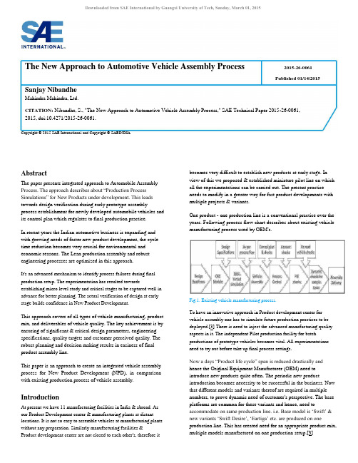
Downloaded from SAE International by Guangxi University of Tech, Sunday, March 01, 2015The New Approach to Automotive Vehicle Assembly Process 2015-26-0061Published 01/14/2015 Sanjay NibandheMahindra Mahindra, Ltd.CITATION: Nibandhe, S., "The New Approach to Automotive Vehicle Assembly Process," SAE Technical Paper 2015-26-0061, 2015,doi:10.4271/2015-26-0061.Copyright © 2015 SAE International and Copyright © SAEINDIAAbstractThe paper presents integrated approach to Automobile Assembly Process. The approach describes about “Production Process Simulations” for New Products under development. This leads towards design verification during early prototype assembly process establishment for newly developed automobile vehicles and its control plan which regulates to final production practice.In recent years the Indian automotive business is expanding and with growing needs of faster new product development, the cycle time reduction becomes very crucial for environmental and economic reasons. The Lean production assembly and robust engineering processes are optimized in this approach.It's an advanced mechanism to identify process failures during final production setup. The experimentation has resulted towards establishing micro level study and critical stages to be captured well in advance for better planning. The actual verification of design at early stage builds confidence in New Product Development.This approach covers of all types of vehicle manufacturing, product mix, and deliverables of vehicle quality. The key achievement is by ensuring of significant & critical design parameters, engineering specifications, quality targets and customer perceived quality. The robust planning and decision making results in easiness of final product assembly line.This paper is an approach to create an integrated vehicle assembly process for New Product Development (NPD), in comparison with existing production process of vehicle assembly.IntroductionAt present we have 11 manufacturing facilities in India & abroad. As our Product Development center & manufacturing plants at distant locations. It is not so easy to assemble vehicles at manufacturing plants without any preparation. Similarly manufacturing facilities & Product development center are not closed to each other's, therefore it becomes very difficult to establish new products at early stage. In view of this we proposed & established miniature pilot line on which all the experimentations can be carried out. The present practice needs to modify in a greater way for fast product developments with multiple projects & variants.One product - one production line is a conventional practice over the years. Following process flow chart describes about existing vehicle manufacturing process used by OEM's.Fig.1. Existing vehicle manufacturing process.To have an innovative approach in Product development center for vehicle assembly one has to simulate future production practices to be deployed.[3] There is need to inject the advanced manufacturing quality aspects in it. The independent Pilot production facility for batch productions of prototype vehicles becomes vital. All experimentations need to try out before take up final process settings.Now a days “Product life cycle” span is reduced drastically and hence the Original Equipment Manufacturer (OEM) need to introduce new products quite often. The periodic new product introduction becomes necessity to be successful in the business. Now that different models and variants thereof are required in multiple numbers, to prove dynamic need of customer's perspective. The base platforms are common for these variants and hence, need to accommodate on same production line. i.e. Base model is ‘Swift’ & new variants ‘Swift Desire’, ‘Eartiga’ etc. are produced on one production line. This has created need for an appropriate product mix, multiple models manufactured on one production setup.[3]The type of vehicles like monocoque, semi monocoque and body-over chassis are familiar. All three types of construction needs to have different process setting & sequence while assembly. It needs to accommodate on same line separately or in combination with flexibility. For NPD cycle it needs to be tryout on pilot setup and then make arrangement for final production line. Thus pilot line and simulations becomes the foundation for successful implementation for New Product Development.The integrated process is focusing on lean production practice and cycle time reduction along with design verification, establishing manufacturing quality characteristics & production norms optimization.[1] The task performed across the various projects are almost similar and can be benefit from the proposed process. The focus will be towards optimizing usage of Fixtures, Gauges, Tools, and methods to be deployed for manufacturing with following are the key aspects to be established.1.Design Readiness: Design for Manufacturability (DFM)and Assembly (DFA).2.Design for Serviceability (DFS) and ensure easiness for servableitems.3.Digital mockup & Virtual simulation4.BOM confirmation and compliance5.Assembly Simulation: Process Control specifications6.SOP: Process Control Plan7.Design Verification, Torque Integrity.8.Front Loading for manufacturing quality aspects9.Product Quality mapping10.Production Norms optimization.This paper is a Review of above processes in order to prepare for faster establishment of NPD process and to incorporate for higher design and process level accuracy form the beginning of product launch preparation. Please refer appendix 1 for the innovative approach adopted.1. Design readiness, DFM & DFA: This process provides confirmation for planned sequence of operations, then proper clearances at each stages. It's made applicable for all components & aggregates used in vehicle assembly. In a process confirmation various alternatives are evaluated. Right selection with process sequence & tool can be defined at early stage. This facilitates procurement of the right tools and confirm suitability The new method of virtual simulation provides best norms for fast and easy working. i.e. Cross Car beam bolts fitment is blind area for visibility. This needs high skill & best judgment for operating person else you can't verify as it will be very difficult to verify afterwards. Such critical areas are identified to reduce the dependency of workmen skills to larger extent. [4]The design for manufacturability and design for assembly (DFM & DFA) is confirmed effectively. The micro level details are worked out and process for assembly is defined. i.e. Torque control right angle approach tool with extension will be suitable for narrow space for tightening approach.[6] This process becomes vital important for deciding the assembly practices. Most of the automotive companies are started using these practices. However the scope is quiet vast & unlimited. The entire engineering industry wherever assembly process is involved; will be using it in future. I.e. Computer industry, Watch industry, White goods industry etc.2. Design for Service: Similarly design for serviceability (DFS) is another requirement which needs to confirm at early stage. All serviceable parts from different systems & aggregates may require to remove & refit during service. The set of tools used are quite different than production tools. Hence it needs to confirm adequate clearances for approach of standard tool kit.In few cases standard tools may not be useful unless & until special tools are designed & tried out i.e. removal of lubrication filter due to low access & space available. In such cases special tools are manufactured & provided for large number of service destinations. The specific methods & recommended practice will be planned with DFS study. The virtual study confirms easiness of operations at every level. Adequate time planning can be done to make such tools available for service needs. This process is very important considering long term effects.3. Digital Mockup & Virtual Simulation: In Recent decade the automobile assembly process becomes highly progressive & innovative. The accuracy level required for vehicle assembly needs to be very high in terms of fit finish, overall quality & customer satisfaction. The productivity is also equally important with multiple models/variants of vehicles to produce, simultaneously on the same production line. The process setting at every stage becomes complex.Vehicle assembly process starts with the sequence of operations to follow on assembly conveyor. Every element of sequence relates with tool approach in predetermined way of working. The specifications which are drawn by design, needs to achieve with those tools. The fixtures & methods deployed for easiness of operations plays major role. The space available for component placing & tool accessibility for tightening needs to be considered very carefully.This needs to study in detail with CAD systems at very early stage. Accordingly the layouts, CAD models & proper packaging becomes prerequisite at design stage. Digital Mock up and Virtual simulation needs to plan with details of tools to be deployed. The way the components are placed in assembly sequence & the methods for tightening will be used in DMU. The virtual study will used for complete study of layouts, clearance and space management in packaged condition. In today's world virtual simulation is supported by digital mock-up process & software extensively used for study and decision making. The training needs can be identified and planned in advance. Adequate time planning can be done to make such tools available for service needs. I am sure Auto OEM most of them are using it however other engineering industry can also think over for its wide applications.4.Virtual BOM Verification: The verification of BOM, correct hardware is confirmed at early stage, Virtual BOM simulation is new methodology developed & helped for first time right BOM release before start of physical assembly.5.Assembly Simulation: Process Control Specifications: Physical verification of assembly process is necessary to confirm output of physical simulations. During first pilot batch or prototype stage mostof the parameters are verified. Inputs are given to design & process team about confidence and non-compliance areas. Accordingly design changes are carried out and reconfirm for easiness.The Pilot line is a setup to try out assembly of proto vehicle at miniature line, processes and tools tryout. At first stage of design, all process sequences and innovative concepts about new methods & tools gets verified. The norms are not seen as constrain and the flexibility helps in achieving targets. The optimization of equipment and process confirmation will be carried out well in advance stage. The production norms, gets tryout along with Design for Manufacturing (DFM), Design for Assembly (DFA) and Service Aspect in Manufacturability (SAM) are verified. i.e The new introduction of aggregates like Auto Transmission is to be adoptedin latest vehicles at the proto stage, all functional & fitment tryout, training and practicing can be done at Pilot stage. Afterwards it can be set with refined version at Production line.6. SOP & Process Control plans: Assembly standard operating process (SOP) is defined for consistency in sequence to follow by any operator for ease of operation in given time limit. e.g. door window glass fitment is quite complex for new designs. Hence CAD Virtual simulation are used to establish actual tryout in assembly. This helps to define process. Once actual try out is carried out successfully, it becomes confirmation for process to follow in predetermined sequence. Finally manufacturing team will be trained on this type ofPilot Line. Accordingly SOP & early training is importantfor manufacturing setup of production.“Product specific process control plan” is another important milestone. The engineering team need to take decisions about methods, fixtures, tools & gauges (FTG) to be used during the assembly process. The plan for target production level is key element for design of FTG. Accordingly the process norms are defined & worked out for throughput time & TACT time of operations. The efforts required by operator need to be evaluated to minimize the fatigue for long stretched workouts. E.g. In case of multi utility vehicles the middle seats are heavy in comparison with other parts for operations like Pick, lift, place & fix are the activities which consumes time. Also multiple operators involved & repetitive job create fatigue after some time. Hence manipulators are designed to pick & place with orientation is quite important. If this set up is flexible then this fixtures need to suitable to multiple designs of seats holding and movement. Thus fixture design plays important role in control plan. Another example of flexible powertrain mounting (Engine & Transmission) should be having approach for all six directional movements which brings easiness for aligning, locating & proper positioning.This facilitates need to set to achieve desired production rate with comfortable practice. The arrangement at every stage of production conveyer line will be planned with flow for material feeding, hardware & tools. This will ensure effectiveness for working positions & easy approach at working stages predominantly. The norms are defined with respect to best achievable production rate.Torque Integrity: The next important element of process control is specified as “torque requirement”. The every joint is defined with typeof hardware & applicable torque. The torque value varies from material & hardware used for fixing position. The elasticity limit for plastic part is different than metal part. It depends on tightening surface and clamping location; also material & type of joint makes difference for torqueing values. Once the component is fixed with specified torque value, it need to be retained in a position for long duration to sustain the vibrations from various road conditions & forces exerted on the joints.The study need to carry out at early stage for integrity of torqueing & its life to retain over the period. This can be defined in terms of years or number of kilometers to cover till end of life situation i.e. hardware used for fixing internal trim parts & hardware used for fixing metal to metal parts at suspension joints will have difference in torque value with respect to vibrations & relative movements. Hence specifications becomes critical at every stage.Thereafter the torque retained capacity vary with respect to specifications due to loosening effect due to usage or Life cycle. The reason behind these changes needs to study for material property, number of clamps & its positions. One also needs to anticipate natural tendency of loosening or over tightening effect. The optimistic torque value for every component needs to be set in advance.Residual torque will be confirmed for each clamping/ tightening locations for withholding value. In case the residual torque value changes, it need to be reviewed for right process at early stage. Similarly, if specified values need to revised, the decisions can be taken in advance. E.g. Trim plastic components deformed at localized clamping area which tends to reduce torque against specification value. Similarly number of clamping positions also plays major role, for large components like sheet metal panels, plastic or jute material trim pads.7. Design Verification: The design verification process gets starts with right fitment of components, aggregates without any trouble where predetermined sequence of operations need to follow with specified tools & processes. This provides confirmation for compliance of process. In case of failures, the designs are reevaluated & iterated at early stage. The tolerance stacks & its combined effect on multiple part's fitment needs to be verified.[2] In certain cases human skills become important for fitment of components i.e. the door alignment & adjustment of hardware for gaps & flushness with level of door and body. [9]. It will also affect door locking & unlocking efforts. Predetermined value of door efforts are one of the key parameters for customer perseverance. Similarly pedal efforts are dependent on multiple component's fitment i.e. relates to clutch & brake systems. The components used in assembly, their positions & tolerance, will affect for pedals movements. The resultant is low or high pedal pressure which is another parameter for customer satisfaction. In this way design verification of systems & aggregates are determined for specific requirements.Additionally critical gaps & clearances are another parameter to verify at early design stage.[8] This requires to verify clearances in static conditions between nearest two parts to be measured after assembly. The CAD layout indicates designed gaps & the actual gap available on vehicle needs to compare. The variation in either conditions (i.e. low or high) will have consequential effects. In case of lesser clearance, it may hit to other components or transfer forces / load / heat to the other components which will effect functionality. Inother way; the excessive gap may create effect on opposite side components. The shift condition will be observed and may create effects to the other assembled parts.These situations at static conditions are different than dynamic conditions. The lesser gaps will make assembly critical & create some of the issues related to noise and vibrations, and in worst condition failures. The engine rock at idle RPM & due to rubber mounts characteristics; it will allow engine oscillations. Hence it requires to confirm for adequate clearance during working conditions. There should be safe gap to avoid hit & failure with other components. Similarly hoses & pipes need to retain in the position & have flexibility even in rocking conditions. Otherwise fuel pipe, brake Bundy tubes, air & water hoses may get cut & lead to huge failure during running situation of vehicle. Thus overall design verifications with respect to layouts & clearance is vital important.Bill of Material (BOM) is other design verification parameters. Weight comparison & analysis is with respect to CAD & actual is another design verification parameter. Similarly new features introduced on product needs to be verified for its functionality. Inthis way multiple verification factors need to confirm at early stage.8.Front Loading of Manufacturing Quality aspects: The assembly process is normally looked as completion of parts fitment in sequential manners and compliance of certain quality parameters. At every stage one need to confirm functionality i.e. switch should operate head lamp, tail lamp or any electrical function. To confirm the right fitment & functional aspects of component or aggregate. We need to make stage wise checking facility. The small gazettes are designed & introduced to check the functionality. E.g. window winding motor fitment on door panel need immediate check with electrical supply & confirm proper working of winding mechanism for full operating length. The check points are involved at every stage & ensured allocated time is adequate to confirm product functionality effectively. In few locations, high complexity involved e.g. Ignition& instrument cluster where checking of head lamps, side indicator lamps, AC blowers, Instrument panel indicators etc. are quite complex. Functional checks becomes very critical, this avoids the repair & rectification at later stage to achieve first time right. This also will helpfor the better product quality establishment for first time right assembly. Stage buy-offs are involved for quality target achievement & establish ownership of the team responsible for delivery. Usually these are static check points followed for product improvements. At this stage,software flashing, vehicle data entry & performance checking parameters through SCADA systems are well recognized practice in industry which need to be adopted at ProductDevelopment Centre. Similarly facilities like brake & roller tester, Suspension Rumbles are required to establish for basic braking & suspension setting. Without this suspension permanent set &bushes torqueing will lead towards failures.[1]9.Quality Parameters mapping: Every vehicle will have list of quality parameters to be checked & established right from the early stage. NPD also demands for validation of those functional aspects before it introduce in the production vehicles. After rolling down the vehicles from miniature line static checks, Dynamic checks & advanced checks will be carried out on new products & this establish the future quality targets for production vehicles. The early mapping is helping for decision making & establishing product quality well in advance stage.Static checks - Door closing effectiveness & sealing effect shall be checked with water spray test or smoke test in conformity with standards. The wind screen wiping effectiveness of wiper system are checked to ensure First Time Right.Next stage is dynamic checks, which evolves initial running of the vehicle after completion of prerequisites checks. In first cut feel, we will come to know about acceleration, drivability, suspension & steering responses & any abnormality. The couple of important parameters which provides customer delight are measured with special tools & processes e.g. Clutch & brake pedal efforts, door opening & closing efforts, Steering efforts, Seat tracking efforts, Seat recliner mechanism efforts, gear shift lever efforts, Key opening efforts, approach to various switches & knobs of lighting system, audio system & their functional efforts. Additionally few check points pertaining to mirror operating approach & efforts, all three mirrors visibility, legibility of instrument cluster with lights on/off condition during day & night time, HVAC/AC systems, air flow & temperature, comfort at different locations, seat belt comfort/ access.Certain points related to ergonomic checks also needs to confirm for designer's input & better quality of the product e.g. Ingress/Egress at all seat locations, access to luggage compartment & glove box etc.All the parameters are taken care to avoid subjective feel and make it objective with measurement.Advances Checks: these are the check points for which the experts need to be involved & provide training to team. The parameters like identify abnormal noises of engine, gearbox and gear lever etc. The effect of vibration & rattle, shake on various components like floor panel, pedals, door trims, seat vibrations etc. Similarly checking for engine start & stop noise, clutch operational noise, throttle operation & response noise are identified by experts. The quality ratings are given for the vehicle towards overall feel, noise and comfort of vehicle drive. Similarly seat comfort, in-cab noise & exterior noise are also identified & considered for quality rating. In this process standards for measurement system will be established to refer in Production.Based on the New Product Development process in terms of design verification parameters, Fit & Functional checks & Product Quality Parameters, we defined the index. This index is measured for every new vehicle & achieve the desired target level before introduction in production.10. Production Norms Optimization: Next important process for vehicle assembly will be productivity consideration and norms finalization. The production norms are generally planned with respect to target production and jobs per hour delivery (JPH). The JPH will be finalized with respect to material feeding schedules, the overall stages timing, distance to walk for pick & place, tools approach for clamping & tightening, filling of coolant, fuel, AC gas, brake oil, engine & transmission oil, axle oils as per desired quantity as planned & worked out. The flow rate, feeder rate are also considered for balancing of norms & TACT time. Accordingly the stages are managed & conveyor speeds are set with optimized level. This involves basic skills by workmen for the job completion. Thetrainings need to provide to working team & setting the stage layouts. On this basis, the lean production norms are determined. Accordingly trained manpower will be allotted for set production target. As per production demands, resources are assigned and output will be achieved. The study carried out for different vehicle models and variants & based on that effective production time utilization is worked out.All three types of vehicles i.e. monocoque, semi monocoque and body- over chassis will need different setting & sequence. Individual different production set ups are established separately.Case StudyThis integrated & innovative process was experimented for first time for proto stage of the new vehicle under development. This process knowledge is disseminated to concerned manufacturing plants which saved their valuable time in establishing the New Product Line and fast ramp up of production in line with market demand.Design team received inputs at early phase and the following arethe benefits derived out of this process:1.Cycle time reduction for NPD: Time required to complete Firstbatch of 54 prototype vehicles with conventional static buildprocess was 27 weeks (7 months), whereas with new process i.e.build on Proto pilot miniature line, it has reduced to 16 weeks (4 months) and the total time saved is 12 weeks (3 months).2.FIRST TIME RIGHT product development, number ofengineering design changes reduced by 33% from firstbuild phase to second build phase.3.It is observed that number of manufacturing related concernsreduced from 815 to 184 (Reduction by 77%) in the project& Open concerns reduced from 210 to 19 (Reduction by 90%)over a period of time of 5 months.4.Design team worked to correct engineering specifications atearly stage & as a result Engineering Specifications Test scoreimproved from 54% to 70% at first phase of Prototype build.5.The result of continuous monitoring of torque parametersand necessary changes in torque specifications consideringTorque Integrity inputs. Torque Integrity score improvedfrom 80% to 96%.6.The customer perceived audit rating, number of concernsreduced from 250 to 155 at prototype stage, further concernresolution was targeted with better quality of supply andfinal process at production line. Target of less than 20concerns achieved before SOP.7.Continuous monitoring of build assessment parameters resultedin improvement in Build Quality Index from 3 to 6 in firstphase of prototype build and finally reached to level of 9before handover to production.8.Percentage of Not OK DVP parameters reduced from 50% to1.83%.9.Simulation of Fixtures Tools & Gauges carried out at firstphase of prototype build, helped Manufacturing Engineeringteam for readiness with all necessary Fixtures Tools & Gaugesbefore start of second phase of Prototype build itself. Tool TryOut phase deleted from development cycle, resulted in cost &time saving by 2 months. 10.As a result of integrated process production ramp upduration reduced from 12-15 weeks to 07 Weeks.11.Cascading unique Mahindra Product Development System Gen-IV process across all new products and locations.Conclusion1.The existing vehicle assembly knowledge is extended for earlydevelopment of prototype to establish newly designed products.2.The miniature pilot line is essential for multi-locationproduct manufacturing process establishment.3.To establish new products for production, the system needto study in advance by digital mockup and virtual simulationprocess at Prototyping stage & gain the design confidence.4.Engineering specifications are required at early stage todefine and set acceptance limits. This will help to achievecustomer touch points at initial stage of prototyping.5.Assembly process simulation of new design is carried outduring first stage of prototype and design confidence is gainedwell in advance.6.The design verification is vital important process to improveon design and confirm easiness in fitment and functional aspect, provided confidence with outcome of FTG & SOP.7.The process control plan, Tools & Fixtures design are specificto norms.8.The Front loading is very crucial during manufacturing processfor first time right product development.9.The optimization of resources was the key ingredient forLean production with product mix and variants. The SOP isderived for deployment.10.Vehicle constructions of all platforms are tried out onunique dynamic Proto Pilot line.11.The successful implementation with very careful and microlevel plans are innovative approach to tryout at pilot stage.References1.Morgan James M; Liker Jeffery K, “The Toyota ProductDevelopment systems” Integrating People, Process, andTechnology, Productivity Press, New York, ISBN-10:1563272822, ISBN-13: 978-1563272820, 2006.2.Nicolas, C., Hugo, F., François, T., Pierre, B. et al., “ANew Approach for Best Fit Assembly Based on theBehaviour of Components,” SAE Technical Paper 2006-01-3174, 2006, doi:10.4271/2006-01-3174.3.Krammer, P., Neef, D., and Plapper, P., “AdvancedManufacturing Technologies for General Assem bly,” SAETechnical Paper 2011-01-1253, 2011, doi:10.4271/2011-01-1253.4.Koganti, R., Zaluzec, M., Chen, M., and Defersha, F., “Designfor Integrated Assembly and Disassembly of AutomotiveProducts,” SAE Technical Paper 2006-01-1423, 2006,doi:10.4271/2006-01-1423.5.da Silva, P., “Concept Car: Excellence in Preparing People forNew Car Releases,” SAE Technical Paper 2006-01-2847, 2006, doi:10.4271/2006-01-2847.。
车辆工程外文翻译---汽车悬架如何工作
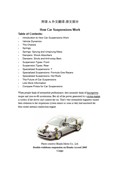
附录A外文翻译-原文部分How Car Suspensions WorkTable of Contents:› Introduction to How Car Suspensions Work› Vehicle Dynamics› The Chassis› Springs› Springs: Sprung and Unsprung Mass› Dampers: Shock Absorbers› Dampers: Struts and Anti-sway Bars› Suspension Types: Front› Suspension Types: Rear› Specialized Suspensions: T› Specialized Suspensions: Formula One Racers› Spec ialized Suspensions: Hot Rods› The Future of Car Suspensions› Lots More Information› Compare Prices for Car SuspensionsWhen people think of automobile performance, they normally think of horsepower, torque and zero-to-60 acceleration. But all of the power generated by a piston engine is useless if the driver can't control the car. That's why automobile engineers turned their attention to the suspension system almost as soon as they had mastered the four-stroke internal combustion engine.Photo courtesy Honda Motor Co., Ltd.Double-wishbone suspension on Honda Accord 2005CoupeThe job of a car suspension is to maximize the friction between the tires and the road surface, to provide steering stability with good handling and to ensure the comfort of the passengers. In this article, we'll explore how car suspensions work, how they've evolved over the years and where the design of suspensions is headed in the future.Vehicle DynamicsIf a road were perfectly flat, with no irregularities,suspensions wouldn't be necessary. But roads are far fromflat. Even freshly paved highways have subtle imperfectionsthat can interact with the wheels of a car. It's theseimperfections that apply forces to the wheels. According toNewton's laws of motion, all forces have both magnitude anddirection. A bump in the road causes the wheel to move upand down perpendicular to the road surface. The magnitude,of course, depends on whether the wheel is striking a giantbump or a tiny speck. Either way, the car wheel experiences avertical acceleration as it passes over an imperfection.Without an intervening structure, all of wheel's vertical energy is transferred to the frame, which moves in the same direction. In such a situation, the wheels can lose contact with the road completely. Then, under the downward force of gravity, the wheels can slam back into the road surface. What you need is a system that will absorb the energy of the vertically accelerated wheel, allowing the frame and body to ride undisturbed while the wheels follow bumps in the road.The study of the forces at work on a moving car is called vehicle dynamics, and you need to understand some of these concepts in order to appreciate why a suspension is necessary in the first place. Most automobile engineers consider the dynamics of a moving car from two perspectives:∙Ride - a car's ability to smooth out a bumpy road∙Handling - a car's ability to safely accelerate, brake and cornerThese two characteristics can be further described in three important principles - road isolation, road holding and cornering. The table below describes these principles and how engineers attempt to solve the challenges unique to each.A car's suspension, with its various components, provides all of the solutions described.Let's look at the parts of a typical suspension, working from the bigger picture of the chassis down to the individual components that make up the suspension proper.The ChassisThe suspension of a car is actually part of the chassis, which comprises all of the important systems located beneath the car's body.ChassisThese systems include:∙The frame - structural, load-carrying component that supports the car's engine and body, which are in turn supported by the suspension∙The suspension system - setup that supports weight, absorbs and dampens shock and helps maintain tire contact∙The steering system - mechanism that enables the driver to guide and direct the vehicle∙The tires and wheels - components that make vehicle motion possible by way of grip and/or friction with the roadSo the suspension is just one of the major systems in any vehicle.With this big-picture overview in mind, it's time to look at the three fundamental components of any suspension: springs, dampers and anti-sway bars.SpringsToday's springing systems are based on one of four basic designs:Coil springs - This is the most common type of spring and is, in essence, aheavy-duty torsion bar coiled around an axis. Coil springs compress and expand to absorb the motion of the wheels.∙Leaf springs - This type of spring consists of several layers of metal (called "leaves") bound together to act as a single unit. Leaf springs were first used on horse-drawn carriages and were found on most American automobiles until 1985. They are still used today on most trucks and heavy-duty vehicles.∙Torsion bars - Torsion bars use the twisting properties of a steel bar to provide coil-spring-like performance. This is how they work: One end of a bar is anchored to the vehicle frame. The other end is attached to a wishbone,which acts like a lever that moves perpendicular to the torsion bar. When the wheel hits a bump, vertical motion is transferred to the wishbone and then, through the levering action, to the torsion bar. The torsion bar then twistsalong its axis to provide the spring force. European carmakers used thissystem extensively, as did Packard and Chrysler in the United States, through the 1950s and 1960s.Photo courtesy HowStuffWorks ShopperTorsion bar∙Air springs - Air springs, which consist of a cylindrical chamber of air positioned between the wheel and the car's body, use the compressive qualities of air to absorb wheel vibrations. The concept is actually more than a century old and could be found on horse-drawn buggies. Air springs from this era were made from air-filled, leather diaphragms, much like a bellows; they werereplaced with molded-rubber air springs in the 1930s.Photo courtesy HSW ShopperAir springsBased on where springs are located on a car -- i.e., between the wheels and the frame -- engineers often find it convenient to talk about the sprung mass and the unsprung mass.Springs: Sprung and Unsprung MassThe sprung mass is the mass of the vehicle supported on the springs, while the unsprung mass is loosely defined as the mass between the road and the suspension springs. The stiffness of the springs affects how the sprung mass responds while the car is being driven. Loosely sprung cars, such as luxury cars (think Lincoln Town Car), can swallow bumps and provide a super-smooth ride; however, such a car is prone to dive and squat during braking and acceleration and tends to experience body sway or roll during cornering. Tightly sprung cars, such as sports cars (think Mazda Miata), are less forgiving on bumpy roads, but they minimize body motion well, which means they can be driven aggressively, even around corners.So, while springs by themselves seem like simple devices, designing and implementing them on a car to balance passenger comfort with handling is a complex task. And to make matters more complex, springs alone can't provide a perfectly smooth ride. Why? Because springs are great at absorbing energy, but not so good at dissipating it. Other structures, known as dampers, are required to do this.Dampers: Shock AbsorbersUnless a dampening structure is present, a car spring will extend and release the energy it absorbs from a bump at an uncontrolled rate. The spring will continue to bounce at its natural frequency until all of the energy originally put into it is used up.A suspension built on springs alone would make for an extremely bouncy ride and, depending on the terrain, an uncontrollable car.Enter the shock absorber, or snubber, a device that controls unwanted spring motion through a process known as dampening. Shock absorbers slow down and reduce the magnitude of vibratory motions by turning the kinetic energy of suspension movement into heat energy that can be dissipated through hydraulic fluid. To understand how this works, it's best to look inside a shock absorber to see its structure and function.A shock absorber is basically an oil pump placed between the frame of the car and the wheels. The upper mount of the shock connects to the frame (i.e., the sprung weight), while the lower mount connects to the axle, near the wheel (i.e., the unsprung weight). In a twin-tube design, one of the most common types of shock absorbers, the upper mount is connected to a piston rod, which in turn is connected to a piston, which in turn sits in a tube filled with hydraulic fluid. The inner tube is known as the pressure tube, and the outer tube is known as the reserve tube. The reserve tube stores excess hydraulic fluid.When the car wheel encounters a bump in the road and causes the spring to coil and uncoil, the energy of the spring is transferred to the shock absorber through the upper mount, down through the piston rod and into the piston. Orifices perforate the piston and allow fluid to leak through as the piston moves up and down in the pressure tube. Because the orifices are relatively tiny, only a small amount of fluid, under great pressure, passes through. This slows down the piston, which in turn slows down the spring.Shock absorbers work in two cycles -- the compression cycle and the extension cycle. The compression cycle occurs as the piston moves downward, compressing the hydraulic fluid in the chamber below the piston. The extension cycle occurs as the piston moves toward the top of the pressure tube, compressing the fluid in the chamber above the piston. A typical car or light truck will have more resistance during its extension cycle than its compression cycle. With that in mind, thecompression cycle controls the motion of the vehicle's unsprung weight, while extension controls the heavier, sprung weight.All modern shock absorbers are velocity-sensitive -- the faster the suspension moves, the more resistance the shock absorber provides. This enables shocks to adjust to road conditions and to control all of the unwanted motions that can occur in a moving vehicle, including bounce, sway, brake dive and acceleration squat.Dampers: Struts and Anti-sway BarsAnother common dampening structure is the strut -- basically a shock absorber mounted inside a coil spring. Struts perform two jobs: They provide a dampening function like shock absorbers, and they provide structural support for the vehicle suspension. That means struts deliver a bit more than shock absorbers, which don't support vehicle weight -- they only control the speed at which weight is transferred in a car, not the weight itself. Because shocks and struts have so much to do with the handling of a car, they can be considered critical safety features. Worn shocks and struts can allow excessive vehicle-weight transfer from side to side and front to back. This reduces the tire's ability to grip the road, as well as handling and braking performance.Anti-sway BarsAnti-sway bars (also known as anti-roll bars) are used along with shock absorbers or struts to give a moving automobile additional stability. An anti-sway bar is a metal rod that spans the entire axle and effectively joins each side of the suspension together.When the suspension at one wheel moves up and down, the anti-sway bar transfers movement to the other wheel. This creates a more level ride and reduces vehicle sway. In particular, it combats the roll of a car on its suspension as it corners. For thisreason, almost all cars today are fitted with anti-sway bars as standard equipment, although if they're not, kits make it easy to install the bars at any time.Suspension Types: FrontSo far, our discussions have focused on how springs and dampers function on any given wheel. But the four wheels of a car work together in two independent systems -- the two wheels connected by the front axle and the two wheels connected by the rear axle. That means that a car can and usually does have a different type of suspension on the front and back. Much is determined by whether a rigid axle binds the wheels or if the wheels are permitted to move independently. The former arrangement is known as a dependent system, while the latter arrangement is known as an independent system. In the following sections, we'll look at some of the common types of front and back suspensions typically used on mainstream cars.Front Suspension - Dependent SystemsDependent front suspensions have a rigid front axle that connects the front wheels. Basically, this looks like a solid bar under the front of the car, kept in place by leaf springs and shock absorbers. Common on trucks, dependent front suspensions haven't been used in mainstream cars for years.Front Suspension - Independent SystemsIn this setup, the front wheels are allowed to move independently. The MacPherson strut, developed by Earle S. MacPherson of General Motors in 1947, is the most widely used front suspension system, especially in cars of European origin.The MacPherson strut combines a shock absorber and a coil spring into a single unit. This provides a more compact and lighter suspension system that can be used for front-wheel drive vehicles.The double-wishbone suspension, also known as an A-arm suspension, is another common type of front independent suspension.Double-wishbone suspension on Honda Accord 2005CoupeWhile there are several different possible configurations, this design typically uses two wishbone-shaped arms to locate the wheel. Each wishbone, which has two mounting positions to the frame and one at the wheel, bears a shock absorber and a coil spring to absorb vibrations. Double-wishbone suspensions allow for more control over the camber angle of the wheel, which describes the degree to which the wheels tilt in and out. They also help minimize roll or sway and provide for a more consistent steering feel. Because of these characteristics, the double-wishbone suspension is common on the front wheels of larger cars.Now let's look at some common rear suspensions.Suspension Types: RearRear Suspension - Dependent SystemsIf a solid axle connects the rear wheels of a car, thenthe suspension is usually quite simple -- based eitheron a leaf spring or a coil spring. In the former design,the leaf springs clamp directly to the drive axle. Theends of the leaf springs attach directly to the frame,and the shock absorber is attached at the clamp thatholds the spring to the axle. For many years,American car manufacturers preferred this designbecause of its simplicity. The same basic design can be achieved with coil springs replacing the leaves. In this case, the spring and shock absorber can be mounted as a single unit or as separate components. When they're separate, the springs can be much smaller, which reduces the amount of space the suspension takes up.Rear Suspension - Independent SuspensionsIf both the front and back suspensions are independent, then all of the wheels are mounted and sprung individually, resulting in what car advertisements tout as"four-wheel independent suspension." Any suspension that can be used on the front of the car can be used on the rear, and versions of the front independent systemsdescribed in the previous section can be found on the rear axles. Of course, in the rear of the car, the steering rack -- the assembly that includes the pinion gear wheel and Photo courtesyHowStuffWorks Shopper Leaf springenables the wheels to turn from side to side -- is absent. This means that rear independent suspensions can be simplified versions of front ones, although the basic principles remain the same.Specialized Suspensions: The Baja BugFor the most part, this article has focused on the suspensions of mainstream front- and rear-wheel-drive cars -- cars that drive on normal roads in normal driving conditions. But what about the suspensions of specialty cars, such as hot rods, racers or extreme off-road vehicles? Although the suspensions of specialty autos obey the same basic principles, they do provide additional benefits unique to the driving conditions they must navigate. What follows is a brief overview of how suspensions are designed for three types of specialty cars -- Baja Bugs, Formula One racers and American-style hot rods.Baja BugsThe Volkswagen Beetle or Bug was destined to become a favorite among off-road enthusiasts. With a low center of gravity and engine placement over the rear axle, the two-wheel-drive Bug handles off-road conditions as well as some four-wheel-drive vehicles. Of course, the VW Bug isn't ready for off-road conditions with its factory equipment. Most Bugs require some modifications, or conversions, to get them ready for racing in harsh conditions like the deserts of Baja California.One of the most important modifications takes place in the suspension. Thetorsion-bar suspension, standard equipment on the front and back of most Bugs between 1936 and 1977, can be raised to make room for heavy-duty, off-road wheels and tires. Longer shock absorbers replace the standard shocks to lift the body higher and to provide for maximum wheel travel. In some cases, Baja Bug converters remove the torsion bars entirely and replace them with multiple coil-over systems, an aftermarket item that combines both the spring and shock absorber in one adjustable unit. The result of these modifications is a vehicle that allows the wheels to travelvertically 20 inches (50 cm) or more at each end. Such a car can easily navigate rough terrain and often appears to "skip" over desert washboard like a stone over water.Specialized Suspensions: Formula One RacersThe Formula One racing car represents the pinnacle of automobile innovation and evolution. Lightweight, composite bodies, powerful V10 engines and advanced aerodynamics have led to faster, safer and more reliable cars.To elevate driver skill as the key differentiating factor in a race, stringent rules and requirements govern Formula One racecar design. For example, the rules regulating suspension design say that all Formula One racers must be conventionally sprung, but they don't allow computer-controlled, active suspensions. To accommodate this, the cars feature multi-link suspensions, which use a multi-rod mechanism equivalent to a double-wishbone system.Recall that a double-wishbone design uses two wishbone-shaped control arms to guide each wheel's up-and-down motion. Each arm has three mounting positions -- two at the frame and one at the wheel hub -- and each joint is hinged to guide the wheel's motion. In all cars, the primary benefit of a double-wishbone suspension is control. The geometry of the arms and the elasticity of the joints give engineers ultimate control over the angle of the wheel and other vehicle dynamics, such as lift, squat and dive. Unlike road cars, however, the shock absorbers and coil springs of a Formula One racecar don't mount directly to the control arms. Instead, they are oriented along the length of the car and are controlled remotely through a series of pushrods and bell cranks. In such an arrangement, the pushrods and bell cranks translate the up-and-down motions of the wheel to the back-and-forth movement of the spring-and-damper apparatus.Specialized Suspensions: Hot RodsThe classic American hot rod era lasted from 1945 to about 1965. Like Baja Bugs, classic hot rods required significant modification by their owners. Unlike Bugs, however, which are built on Volkswagen chassis, hot rods were built on a variety of old, often historical, car models: Cars manufactured before 1945 were considered ideal fodder for hot rod transformations because their bodies and frames were often in good shape, while their engines and transmissions needed to be replaced completely. For hot rod enthusiasts, this was exactly what they wanted, for it allowed them to install more reliable and powerful engines, such as the flathead Ford V8 or the Chevrolet V8.The Future of Car SuspensionsWhile there have been enhancements and improvements to both springs and shockabsorbers, the basic design of car suspensions has not undergone a significant evolution over the years. But all of that's about to change with the introduction of a brand-new suspension design conceived by Bose -- the same Bose known for its innovations in acoustic technologies. Some experts are going so far as to say that the Bose suspension is the biggest advance in automobile suspensions since the introduction of an all-independent design.How does it work? The Bose system uses a linear electromagnetic motor (LEM) at each wheel in lieu of a conventional shock-and-spring setup. Amplifiers provide electricity to the motors in such a way that their power is regenerated with each compression of the system. The main benefit of the motors is that they are not limited by the inertia inherent in conventional fluid-based dampers. As a result, an LEM can extend and compress at a much greater speed, virtually eliminating all vibrations in the passenger cabin. The wheel's motion can be so finely controlled that the body of the car remains level regardless of what's happening at the wheel. The LEM can also counteract the body motion of the car while accelerating, braking and cornering, giving the driver a greater sense of control.Unfortunately, this paradigm-shifting suspension won't be available until 2009, when it will be offered on one or more high-end luxury cars. Until then, drivers will have to rely on the tried-and-true suspension methods that have smoothed out bumpy rides for centuries.For more information on car suspensions and related topics, check out the links on the next page.附录B 外文翻译-译文部分汽车悬架如何工作目录列表:对汽车悬架如何工作的介绍车辆动力学底盘弹簧弹簧:簧载质量和非簧载质量减震器:震动吸收装置减震器:减震器支柱和横向稳定杆悬架形式:前悬架悬架形式:后悬架特种悬架:T型悬架特种悬架:一级方程式赛车悬架特种悬架:改装车悬架未来汽车悬架更多信息汽车悬架的价格比较当人们提到汽车的性能时,人们通常会想到功率、扭矩和0到60的加速时间。
(完整版)车辆工程专业英语核心词汇总汇
Unit 1 Automobile Basicsspare wheel 备胎lubricate 润滑(名词是lubrication )gearbox 变速箱frame 车架transmission 变速器hood 发动机罩(=bonnet )→ decklid = trunklid 行李箱盖chassis chassis ['ʃæsi]['ʃæsi]底盘crankshaft 曲轴carburetor carburetor [,kɑːbjʊ'retə][,kɑːbjʊ'retə]化油器spark plug 火花塞clutch 离合器driveshaft 传动轴drive train 传动链petroleum petroleum [pə'trolɪəm][pə'trolɪəm]石油propane 丙烷gasohol 酒精混合燃料Unit 2 Bodies bracket 支架labyrinth labyrinth ['læbərɪnθ]['læbərɪnθ]迷宫cross-member 横梁interposition 干涉steering wheel 方向盘three-box car 三厢车hinge 铰链bumper 保险杠windshield 挡风玻璃windshield wiper 雨刮器interior trim 内饰instrument panel = dashboard 仪表盘safety belt 安全带unibody 承载式车身rubber bush 橡胶衬套vibration 振动ancillary 辅助的stress 应力fender 翼子板curb weight 整备质量intake duct 进气道fatigue 疲劳demist 除雾loudspeaker 扬声器Unit 3 Engines sprocket 链齿轮cylinder 汽缸connecting rod 连杆valve 气门camshaft 凸轮轴lifter 挺杆rocker arm 摇臂valve train 配气机构Unit 4 Fuel System clamp 夹具fuel rail 油轨intake manifold 进气歧管exhaust manifold 排气歧管throttle 节气门squirt 喷射hothouse 温室Unit 5 Electric System circuit 电路coil 线圈ignition 点火alternator 发电机ammeter 安培计voltage regulator 稳压器insulation 绝缘distributor 分电器transistor 晶体管fuse 保险relay 继电器headlights 大灯dome light 顶灯fog lamp 雾灯dash 仪表板halogen 卤素filament 灯丝LED(Light Emitting Diodes)发光二极管Unit 6 Cooling and Lubricating Systems wear 磨损contamination 污染coolant 冷却液radiator 散热器thermostat 节温器grill 格栅,进风口centrifugal force 离心力centripetal force 向心力boiling point 沸点overflow tube 溢流管wax 蜡oil filter 机油滤清器oil pan 油底壳oil galleries 油孔sealing 密封nozzle 喷嘴meshing gear 啮合齿轮bearing 轴承horsepower 马力Unit 7 Exhaust and Emission Control System header pipe 集气管three-way catalytic converter 三元催化转化器三元催化转化器catalyst 催化剂muffler 消音器hanger 挂钩heat shield 隔热板heavy-duty 耐用的,重负荷的fume 烟hydrocarbon 碳氢化合物evaporate 蒸发(名词后缀是-ion)additive 添加剂coupling 连接器gasket 垫圈odorless 无味的positive crankcase ventilation 曲轴箱强制通风曲轴箱强制通风grove 沟槽oil dipstick 油尺vacuum valve 真空阀charcoal canister 活性炭阀idle speed 怠速EGR(Exhaust Gas Recirculation)废气再循环platinum 铂palladium 钯rhodium 铑ceramic 陶瓷的honeycomb 蜂窝状Unit 8 Suspension System, Steering System and Brake System passenger cars/vehicles 乘用车commercial cars/vehicles 商用车bump 路面凸起alignment 校准steering knuckle 转向节swivel 旋转spring 弹簧(sprite 雪碧)ball joint 球型接头shock absorber = damper 减震器bounce 谈起bushing 衬套non-independent suspension 非独立悬架recirculating call steering systems 循环球式转向器rack-and-pinion steering systems 齿轮齿条式转向器齿轮齿条式转向器lorry 货车(也有卡车的意思)truck 卡车worm gear 涡轮蜗杆机构steering linkage 转向连杆steering column 柱pitman arm 转向摇臂track rod 转向横拉杆idler arm 随动臂sleeve 衬套master cylinder 制动主缸lever 杠杆brake booster 制动助力器engine compartment 发动机舱housing 外壳,壳体malfunction 故障,失灵cable 线缆caliper 卡钳brake pads 摩擦片hub 轮毂squeeze 压缩brake shoe 制动蹄Unit 9 Drive Trains and Axlesdrive axles 驱动桥MT(Manual Transmission)手动变速器AT(Automatic Transmission)自动变速器CVT(Continuously Variable Transmission)无级变速器stationary 静态的release bearing 分离轴承clutch fork 离合器拨叉pressure plate 压盘tension 张力hydraulic circuit 液压回路throw-out bearing = release bearing 分离轴承torque converter 液力变矩器friction 摩擦synchronizer 同步器shift linkage 换挡连杆机构turbine 涡轮stator 导轮planet gears 行星齿轮planet gear carrier 行星架行星架ring gear 齿圈slip yoke 滑动叉differential 差速器axle housing 桥壳unsprung weight 簧下质量sprung weight 簧上质量Unit 10 Safety, Security and Navigation Systems occupant = passenger乘员buckle 安全带插扣impact 碰撞regulatory 法规nylon 尼龙stiffness 刚度abrasion 磨损kinetic 运动学的inertia 惯性trigger 触发器resister 电阻GPS(Global Positioning System)全球定位系统补充:assembly line装配线stabilizer bar横向稳定杆cylinder block 气缸体cast iron/aluminium 铸铁/铝turbocharge 涡轮增压supercharge 机械增压exhaust pipe 排气管displacement排量compression ratio压缩比valve overlap 气门重叠thrust washer 止推垫圈ductile iron 球墨铸铁constant velocity joint 等速万向节等速万向节SUV (Sport Utility Vehicle )运动型多功能车)运动型多功能车常见品牌:Toyota 丰田Honda 本田Nissan 日产Mazda 马自达Lexus 雷克萨斯Suzuki 铃木Mitsubishi 三菱General Motors 通用Cadillac 凯迪拉克Lincoln 林肯Ford 福特Chrysler 克莱斯勒Corvette 克尔维特Mercedes Mercedes [mə'sidi:z][mə'sidi:z][mə'sidi:z] Benz 梅赛德斯-奔驰Volkswagen 大众Audi 奥迪Rolls Royce 劳斯莱斯Bentley 宾利Ferrari 法拉利Maserati 玛莎拉蒂Aston Martin 阿斯顿马丁Jaguar 捷豹Porsche 保时捷Lamborghini 兰博基尼Koenigsegg 柯尼塞格Bugatti 布加迪Pagani 帕加尼Alfa Romeo 阿尔法罗密欧Volvo 沃尔沃Lotus 莲花a m n d A l t h g sb i e o f rRenault 雷诺Hyundai 现代Peugeot 标志Opel 欧宝Fiat 菲亚特Skoda 斯柯达Citroen 雪铁龙Dodge 道奇。
车辆工程外文翻译-汽车主减速器
本科生毕业设计(论文)外文翻译外文题目:AUTOMOTIWE FINAL DRIVE译文题目:汽车主减速器学生姓名:专业:车辆工程指导教师姓名:评阅日期:AUTOMOTIWE FINAL DRIVEFINAL DRIVEA final drive is that part of a power transmission system between the drive shaft and the differential. Its function is to change the direction of the power transmitted by the drive shaft through 90 degrees to the driving axles. At the same time. it provides a fixed reduction between the speed of the drive shaft and the axle driving the wheels.The reduction or gear ratio of the final drive is determined by dividing the number of teeth on the ring gear by the number of teeth on the pinion gear. In passenger vehicles, this speed reduction varies from about 3:1 to 5:1. In trucks it varies from about 5:1 to 11:1. To calculate rear axle ratio, count the number of teeth on each gear. Then divide the number of pinion teeth into the number of ring gear teeth. For example, if the pinion gear has 10 teeth and the ring gear has 30 (30 divided by 10), the rear axle ratio would be 3:1. Manufacturers install a rear axle ratio that provides a compromise between performance and economy. The average passenger car ratio is 3.50:1.The higher axle ratio, 4.11:1 for instance, would increase acceleration and pulling power but would decrease fuel economy. The engine would have to run at a higher rpm to maintain an equal cruising speed.The lower axle ratio. 3:1, would reduce acceleration and pulling power but would increase fuel mileage. The engine would run at a lower rpm while maintaining the same speed.The major components of the final drive include the pinion gear, connected to the drive shaft, and a bevel gear or ring gear that is bolted or riveted to the differential carrier. To maintain accurate and proper alignment and tooth contact, the ring gear and differential assembly are mounted in bearings. The bevel drive pinion is supported by two tapered roller bearings, mounted in the differential carrier. This pinionshaft is straddle mounted. meaning that a bearing is located on each side of the pinion shaft teeth. Oil seals prevent the loss of lubricant from the housing where the pinion shaft and axle shafts protrude. As a mechanic, you will encounter the final drive gears in the spiral bevel and hypoid design.Spiral Bevel GearSpiral bevel gears have curved gear teeth with the pinion and ring gear on the same center line. This type of final drive is used extensively in truck and occasionally in older automobiles. This design allows for constant contact between the ring gear and pinion. It also necessitates the use of heavy grade lubricants.Hypoid GearThe hypoid gear final drive is an improvement or variation of the spiral bevel design and is commonly used in light and medium trucks and all domestic rear- wheel drive automobiles. Hypoid gears have replaced spiral bevel gears because they lower the hump in the floor of the vehicle and improve gear-meshing action. As you can see in figure 5-13, the pinion meshes with the ring gear below the center line and is at a slight angle (less than 90 degrees).Figure 5-13.—Types of final drives.This angle and the use of heavier (larger) teeth permit an increased amount of power to be transmitted while the size of the ring gear and housing remain constant. The tooth design is similar to the spiral bevel but includes some of the characteristics of the worm gear. This permits the reduced drive angle. The hypoid gear teeth have a more pronounced curve and steeper angle, resulting in larger tooth areas and more teeth to be in contact at the same time. With more than one gear tooth in contact, a hypoid design increases gear life and reduces gear noise. The wiping action of the teeth causes heavy tooth pressure that requires the use of heavy grade lubricants.Double-Reduction Final DriveIn the final drives shown in figure 5-13, there is a single fixed gear reduction. This is the only gear reduction in most automobiles and light- and some medium-duty trucks between the drive shaft and the wheels.Double-reduction final drives are used for heavy- duty trucks. With this arrangement (fig. 5-14) it is not necessary to have a large ring gear to get the necessary gear reduction. The first gear reduction is obtained through a pinion and ring gear as the single fixed gear reduction final drive. Referring to figure 5-14, notice that the secondary pinion is mounted on the primary ring gear shaft. The second gear reduction is the result of the secondary pinion which is rigidly attached to the primary ring gear, driving a large helical gear which is attached to the differential case. Double-reduction final drives may be found on military design vehicles, such as the 5-ton truck. Many commercially designed vehicles of this size use a single- or double-reduction final drive with provisions for two speeds to be incorporatedFigure 5-14.—Double-reduction final driveTwo-Speed Final DriveThe two-speed or dual-ratio final drive is used to supplement the gearing of the other drive train components and is used in vehicles with a single drive axle (fig. 5-15). The operator can select the range or speed of this axle with a button on the shifting lever of the transmission or by a lever through linkageThe two-speed final drive doubles the number of gear ratios available for driving the vehicle under various load and roadconditions. For example, a vehicle with a two-speed unit and a five-speed transmission, ten different forward speeds are available. This unit provides a gear ratio high enough to permit pulling a heavy load up steep grades and a low ratio to permit the vehicle to run at high speeds with a light load or no loadThe conventional spiral bevel pinion and ring gear drives the two-speed unit, but a planetary gear train is placed between the differential drive ring gear and the differential case. The internal gear of the planetary gear train is bolted rigidly to the bevel drive gear. A ring on which the planetary gears are pivoted is bolted to the differential case. A member, consisting of the sun gear and a dog clutch, slides on one of the axle shafts and is controlled through a button or lever accessible to the operator When in high range, the sun gear meshes with the internal teeth on the ring carrying the planetary gears and disengages the dog clutch from the left bearing adjusting ring, which is rigidly held in the differential carrier. In this position, the planetary gear train is locked together. There is no relative motion between the differential case and the gears in the planetary drive train. The differential case is driven directly by the differential ring gear, the same as in the conventional single fixed gear final drive.When shifted into low range, the sun gear is slid out of mesh with the ring carrying the planetary gears. The dog clutch makes a rigid connection with the left bearing adjusting ring. Because the sun gear is integral with the dog clutch, it is also locked to the bearing adjusting rings and remains stationary. The internal gear rotates the planetary gears around the stationary sun gear, and the differential case is driven by the ring on which the planetary gears are pivoted. This action produces the gear reduction, or low speed, of the axleDIFFERENTIAL ACTIONThe rear wheels of a vehicle do not always turn at the same speed. When the vehicle is turning or when tire diameters differ slightly, the rear wheels must rotate at different speeds.If there were a solid connection between each axle and the differential case, the tires would tend to slide, squeal, and wear whenever the operator turned the steering wheel of the vehicle. A differential is designed to prevent this problem.Driving Straight AheadWhen a vehicle is driving straight ahead, the ring gear, the differential case, the differential pinion gears, and the differential side gears turn as a unit. The two differential pinion gears do NOT rotate on the pinion shaft, because they exert equal force on the side gears. As a result, the side gears turn at the same speed as the ring gear, causing both rear wheels to turn at the same speed.Turning CornersWhen the vehicle begins to round a curve, the differential pinion gears rotate on the pinion shaft. This occurs because the pinion gears must walk around the slower turning differential side gear. Therefore, the pinion gears carry additional rotary motion to the faster turning outer wheel on the turn..Differential speed is considered to be 100 percent. The rotating action of the pinion gears carries 90 percent of this speed to the slowing mover inner wheel and sends 110 percent of the speed to the faster rotating outer wheel. This action allows the vehicle to make the turn without sliding or squealing the wheels.Figure 5-15.—Two speed final drive汽车主减速器主减速器主减速器是在传动轴和差速器之间的一个动力传动系统的组成部分。
车辆工程转向机构中英文对照外文翻译文献
中英文对照外文翻译文献(文档含英文原文和中文翻译)原文:The Track Vehicle Changes Direction Research Present Condition and DevelopmentTrends of The Organization1 change direction the research present condition of the organizationDifferent classification in basis method, the track vehicle changes direction organization can according to vehicle is in change direction process the power flows of deliver the way is divided into the single power flows to changedirection the organization to flow to change direction the organization with a power, and also can according to in change direction process two the sport of side trackses have no the contact but is divided into the independent type change direction the organization with bad soon the type changes direction the organization.1.1 single powers establish a certain changing direction the organization after flowing change direction the single power in organization flow to change direction the general structure in organization method is at became soon the organization, is the most simple method to constitute track vehicle change direction to spread to move.The single power flows to change direction the organization to change direction the organization most in brief, among them most in common usely change direction the clutch, single bad soon the machine, double is bad soon the machine, planet changes direction organization etc..Change direction the clutch[1,2] is all a friction that several types rub the clutch, depending the friction surface to deliver to turn the , being the separation some on changing direction the clutch laterally, can reduce or cut off that side drive a round delivers of turn the make vehicle changed direction.Change direction the size of the radius from drive a decrease for spreads to turn the measures namely the degree that clutch separate decides.Change direction the clutch is simple because of the construction, manufacturing convenience, got the extensive application on the small scaled track in inside in earlier period type tractor, bulldozer.But because its manipulate the sex bad, produce the efficiency low, can consume bigger, enlarge continuously along with the track vehicle power, change direction the application of the clutch will suffer certainly of restrict.SingleBad soon the machine changes direction the organization[2,3] can make vehicle several why the speed of the center position still keeps in change direction process the original driving the car straightly is soon, being a When the complete system in side move, change direction the radius over small, but another side track speed over high, change direction the Cape speed over big, for this reason a power for needing changing direction power very bigly, would outrunninggenerally launching machine restrict, if the pilot keep on changing direction, have a little bit the immodesty and then will make launch the machine fire, as a result can depend to slip to whet, using than the greater half path changes direction, or pole is not fair and softly break to change direction continuously with the lesser half path.Therefore this kind of is single bad soon the machine change direction the organization to no longer adopt almost now.The speed that a speed for differing soon machine changing direction organization[3,4] can making track vehicle at changing direction slowly soon side track lowering is equal to the fast side track the increment, the for this reason vehicle changes direction of average speed and straightly the speed that drive same alike.But because a variety for badly soon machine can't completely system moving first side track, vehicle can't originally changing direction, and changing direction radius scope has no usage to change direction the clutch big, changing direction the going smoothly worse.While changing direction, the fast side track accelerates, therefore launching the affixture of the machine carry the ratio adoption change direction the clutch big.The double is bad soon the machine be constituted by wheel gear of change direction the organization, with change direction the clutch compare the spare parts number little, bear to whet the sex good, the life span is longer.The planet changes direction the organization[4,5] moves with the system from a planet a department the machine constitutes.The operation planet the system on the organization moves the machine can change two sides drives the round drives the dint size make vehicle changed direction.It is that type of to change direction the organization opposite in change direction the clutch change direction the organization can deliver the bigger changing direction the dint , can realize an athletic and fixed stalk wheel gear organization fall through of two free a planet for of flat-out decomposition with synthesizing, planet organization a three dollar as have the bad relating to soon; change direction the organization to much order to deliver the motive, and the internal path in organization faces the dint mutually equilibrium.But is complicated because of its construction, only industry in big power tractor, bulldozer and other heavy type vehicle last application.Single weakness thatpower change direction is obvious, vehicle only contain several fix of change direction the radius, press to rule not of change direction When the radius change direction, want to is slipped by friction a piece to whet to realize, and is hard to get the stability change direction the radius accurately; the next in order in change direction process rub a dollar piece of violent slip to whet to will bring to have fever with wear away, make spread to move the efficiency lower, especially in the big power change direction work appearance next, would exsit the bigger power lose, with the result that often need to be declined to change direction soon; moreover, the violent friction also make easy damage in organization, cause the work dependable bad, the life span lower.1.2 pairs of powerses flow to change direction the organization after launching machine, will launch the machine power be divided in to become soon with change direction two roads be juxtaposed to deliver, ising a double of powers to flow to change direction the organization.A power flows to change direction the organization will used for keeping the pushes forward of become soon the organization is different from result in leftly, the right side track speed differs of change direction the organization to be juxtaposed in spread move department, change direction the organization when the vehicle keeps the did not result in twoth the speed of side trackses are bad, while changing direction, became to flow each file of offering soon to drive the speed straightly with change direction the organization results in of two the speed of side trackses differ to remit to flow, realizing the vehicle change direction.(1)the machine type a power flow to change direction the organization to flow the foundation top that change direction the organization to appear at the earliest stage in the single power of was a machine to kept the with changed direction two powers flowed all from machinery to realized type a power to flowed to change direction the organization[3].It is this kind to change direction the organization main from two become soon box( a lord become soon the box, a cent moves a box of), the planet wheel gear organization, clutch moves with the planet organization system the machine constitutes, the single power flows to change direction in changing direction function the organization has the very bigincreasing, but it still change direction the radius is to have the class.The file is more low, getting of change direction the radius more small; the file is more high, getting of change direction the radius more big.Can't still adapt to the vehicle road in all different curvatures on the tactful track that change direction to drive with the demand, also can't expel parts of coalescences rub a piece proceeds to slip to whet to change direction and from slip to whet an a series of problem for bringing.(2)the machine liquid press type a power flows to change direction the organization machineThe type of changes direction the organization changes direction the function easily under the influence of the pilot's driver's technique, physical strength term moving the machine to wear away with the clutch, system, and bring the pilot the fatigue easily.Give or get an electric shock along with the machine the liquid press and technical development in engineering in machine in person, the machine type change direction the organization to will be eliminated on the big power tractor, bulldozer...etc. engineering vehicle necessarily.Press in the last additional liquid in system in machine the liquid of —that pump the motor presses the machine — liquid drives to press to change direction the system will get the application gradually.The machine liquid press type a power flows to change direction the organization[5,6] from launch the machine and change the deal pump, control valve, fixed amount motor, many files become soon box and empress bridges change direction to differ to move the organization constitutes.It will spread to flow from the machine that launch the machine power in many files became soon the importation stalk of the box last cent flow, all the way flow through was pressed by liquid pump- liquid press motor constitute of change direction adjust soon system; another all the way flow through many files became soon box, finally experienced star row top confluence, then was lined up by planet of some a the parts( such as planet) spread to the vehicle to spread to move the stalk top eventually.Because the liquid presses to pump to press with the liquid the motor can have no the class controls, therefore using the this type of changing direction the organization since can acquire the carAn a lot of weakness for twoth lateral speeds differing realizing having no class controling, again overcoming machine type changing direction organization.If the liquid presses the motor do not work, only coming from central spread the dynamic power flow, the vehicle makes the straight line drives; if only have the liquid that come from the power press the motor flows, the vehicle can realize to change direction radius as the zero changing direction originally; if input at the same time two road powers flow, because the liquid presses the motor can realize to have no the class controls, for this reason vehicle two side tracks drive the rotation to have soon and will barely do much more endless, can get the much more endless changes direction the radius, can immediately realize to have no the class changes direction, pilot as long as manipulate to change direction the dish turns to move the liquid presses the device, can make vehicle driven along the certain arc stablely.This kind of changes direction the organization not only have the construction good, have no the friction a piece, life span is long, the efficiency is high and work dependable, arrange simple, maintain the adjustment little and lower to can consume to wait the characteristics the outside, but also it is not a motive to pass the part or cut off all a side track in working function to the system move a the side drives a the round realizes to change direction of, but two side tracks deliver the motive always, can realizes nicely like this the motive change direction, basic ascend a safety for slippery phenomenon, being applicable to proceeding being partial to carrying pushing soil with cutting off root homework; at sloping fields changing direction can't appearing" conversing direction" phenomenon, increases vehicle that dissolves the track; because of changing direction do not cut off the motive, the average car of the for this reason vehicle does not lower soon; the track do not stop driving, breaking to the soil little, in loosenning soft soil of pass the sex good; change direction the size of the radius can control arbitrarily, increasing the flexibility of the track vehicle, change direction steady; change direction vehicle can develop with drive the high work in same function straightly; realizes easily a the root manipulates the pole to control in to back with change direction.2 change direction the pure liquid in trend(1)in development in organization press to have no the class changes direction the organization wants to realize the track vehicle changes direction the radius can control and continue to have no the class changes of change direction the function, the adoption capacity type liquid presses to pump to press with the liquid motor etc. has no the class become soon a piece is a more realistic viable method.The pure liquid presses to change direction the organization[7 9] of ~ss pass to pump of positive and negative two directions have no the class changes the deal regulates, realizing to launch the mobile dint was spread by double to move to change direction the road arrives to remit the popular star row has no the class changes of spreading and moving ratio, end realize the vehicle face or so two change direction laterally radius can continue to have no the class the variety keeps the , pass the liquid press to pump with the liquid press the motor shuts the lock( change the row that deal pump measureses for zero) to realize to change direction the zero to shut the lock axially, from but keeps to keep the stablely.Under the situation of becoming soon the organization hangs the blank on schedule to change direction, launch machine a power for sending out all to press from the liquid that change direction the road a piece deliver, can realize the vehicle change direction originally.The current liquid presses the industry level returns the hard getting the power enough and big and the good liquid in function presses a dollar an efficiency for, and the liquid presses the system low, this is the biggest obstacle that pure liquid press to have no the class change direction the technique develops.(2)the compound changes direction organization as to overcome the pure liquid presses the above blemish that change direction the organization, appearing now the small liquid in power in various adoptions press the liquid of a dollar piece presses the compound changes direction the project[7].A pump a motor project: this project is to solves the liquid press the direct and the most simple project in shortage in a power in a dollar, its function press with pure liquid to change direction same, but two sets of liquids press a piece merge to make the organization's physical volume weight bigger, the efficiency is still lower.The machine liquid presses to reunite the project: that project is adopting adouble of flowing the liquid press to change direction of at the same time, reserve a set of machines change direction the organization.Make use of the power not very of the liquid presses a dollar the piece realizes the greater half path changes direction of have no the class variety continuously; make use of the organization that machine change direction lesser half path realizes the class changes direction.This kind of change direction the organization falls through whole radius scope has no the class variety.A radius liquid presses to change direction the project: that project adoption contain two kinds of exportations soon the liquid that compare presses the motor, when the good road ascends to change direction adoption the higher exportation turns soon, native out of fix the hour then change to output with the low speed to overcome bigger changing direction the resistance.The liquid presses the liquid dint compound changes direction the project: that project presses with the liquid of the limited power a piece proceeds to have no the class changes direction, the help matches the machine accidentally at change direction the liquid press the motor dint not enough hour on time provide the help .That project although reduce the liquid press a piece efficiencies would be much lower.In fine, adopt the liquid press a dollar a point for having no class becoming soon characteristic to realizing track vehicle having no class changing direction is good choice, solving liquid pressing a dollar a power shortage then is low with the efficiency that direction is investigative.(3)the machine liquid presses the consecution has no the class changes direction the organization machine liquid presses the consecution has no the class changes direction the organization[10 21] of ~ss are in simple liquid pressing cent in machine spreading the foundation that move the principle, adopting the different machine organization parameter combine, and press with liquid a dollar the piece matches with of a kind of latest model changes direction the organization.It can guarantee at continue to have no the class output the next applied small liquid in premise that turn to press the total power in an exportation for significantly increasing vehicle in a dollar soon, and its spread to move the efficiency far far ahead pure the liquid presses to change direction theorganization spreads to move the efficiency.It represents the development direction that track vehicle change direction organization.The research develops the good machine in function liquid presses the consecution has no the class changes direction the organization, excellent turn to match the that type of turning. Construction parameter that face organization is the point lesson of the current vehicle engineering realm.履带车辆转向机构的研究现状及发展趋势1、转向机构的研究现状依据不同的分类方法,履带车辆转向机构可根据车辆在转向过程中功率流的传递方式分为单功率流转向机构和双功率流转向机构,也可根据在转向过程中两侧履带的运动有无联系而分为独立式转向机构和差速式转向机构。
车辆工程 外文翻译
Research on vehicle Control technology Using Four- wheelIndependent Steering SystemCHEN Si-zhong, SHU Jin,YANG LinJournal of Beijing Institute of Technology, 2006 ,15(1) :22~26对使用四轮独立转向系统的整车控制技术的研究陈思忠,舒进,杨林北京理工大学学报(英文版),2006,15(1):22~26对使用四轮独立转向系统的整车控制技术的研究陈思忠舒进杨林机械与车辆工程学院北京理工大学北京100086中国摘要:通过有效和独立的后轮控制来提高车辆的操控稳定性的技术已经提出。
首先,简要介绍配置四轮独立转向原型车。
然后详细地制定对四轮独立转向系统的电子控制器的整体设计。
四轮独立转向系统是在对质心零侧偏角控制策略的研究下得到的,它的建立是为了推断出分离的后轮转向角度的方程。
根据这些方程,对四轮独立转向车辆性能的仿真分析完成后,显示四轮独立转向车辆在低速的条件下可操作性大大提高,并且在高速条件下操纵稳定性增强。
最后,四轮独立转向车辆路试验证了模拟的正确性,表明了与传统的四轮的转向车辆相比,四轮独立转向不仅提高了车辆运动平稳性,也降低了转向阻力,减轻磨损轮胎。
关键词:四轮独立转向系统控制策略四轮转向系统中国图书馆分类号:U 270文件编码:A文章编号:1004-0579(2006)01-0022-05 最近几年,人们对四轮转向技术下的车辆操作稳定性研究产生了浓厚兴趣。
随着深一步的研究,四轮转向的问题变得越来越多的突出。
因为车辆转弯数学模型的推论往往是以自行车模型作为基础,这样就导致了两后轮转向角在转向时是相同的。
即使后轮转向制动器仅仅用于驱动一个拉杆联动,然而此联动的设计都是相当困难的,因为车辆瞬态转向中心引起后轮转向角连续变化。
所以,四轮独立转向系统是一个优秀的方法,他将运动平稳和四轮转向技术的优势结合起来。
车辆工程外文翻译
(本文截取的是一篇国外学生的毕业论文中的一段论文名字是“A Comprehensive Thermal Management System Model for Hybrid Electric Vehicles”)The automotive industry is facing unprecedented challenges due to energy and environmental issues. The emission regulation is becoming strict and the price of oil is increasing. Thus, the automotive industry requires high-efficiency powertrains for automobiles to reduce fuel consumption and emissions. Among high-efficiency powertrain vehicles, Hy-brid Electric Vehicles (HEVs) are under development and in production as one potential solution to these problems. Thus, one of the most critical objectives of the HEV development is improving fuel economy. There are many ways of maximizing the fuel econo-my of a vehicle such as brake power regeneration,efficient engine operation,parasitic loss minimization,reduction of vehicle aerodynamic drag, and engine idle stop. Figure 1 compares the balance of the energy of a conventional vehicle with a hybrid electric vehicle。
汽车车辆工程外文翻译、制动器外文文献翻译、中英文翻译
外文原文:THE BRAKE BIBLEBrakes - what do they do?The simple answer: they slow you down.The complex answer: brakes are designed to slow down your vehicle but probably not by the means that you think. The common misconception is that brakes squeeze against a drum or disc, and the pressure of the squeezing action is what slows you down. This in fact is only part of the equation. Brakes are essentially a mechanism to change energy types. When you're travelling at speed, your vehicle has kinetic energy. When you apply the brakes, the pads or shoes that press against the brake drum or rotor convert that energy into thermal energy via friction. The cooling of the brakes dissipates the heat and the vehicle slows down. It's the First Law of Thermodynamics, sometimes known as the law of conservation of energy. This states that energy cannot be created nor destroyed, it can only be converted from one form to another. In the case of brakes, it is converted from kinetic energy to thermal energy.Angular force. Because of the configuration of the brake pads and rotor in a disc brake, the location of the point of contact where the friction is generated also provides a mechanical moment to resist the turning motion of the rotor.Thermodynamics, brake fade and drilled rotors.If you ride a motorbike or drive a race car, you're probably familiar with the term brake fade, used to describe what happens to brakes when they get too hot. A good example is coming downa mountain pass using your brakes rather than your engine toslow you down. As you start to come down the pass, the brakes on your vehicle heat up, slowing you down. But if you keep using them, the rotors or drums stay hot and get no chance to cool off. At some point they can't absorb any more heat so the brake pads heat up instead. In every brake pad there is the friction material that is held together with some sort of resin and once this starts to get too hot, the resin starts to vapourise, forming a gas. Because the gas can't stay between the pad and the rotor, it forms a thin layer between the two whilst trying to escape. The pads lose contact with the rotor, reducing the amount of friction and voila. Complete brake fade.The typical remedy for this would be to get the vehicle to a stop and wait for a few minutes. As the brake components cool down, their ability to absorb heat returns and the next time you use the brakes, they seem to work just fine. This type of brake fade was more common in older vehicles. Newer vehicles tend to have less outgassing from the brake pad compounds but they still suffer brake fade. So why? It's still to do with the pads getting too hot. With newer brake pad compounds, the pads transfer heat into the calipers once the rotors are too hot, and the brake fluid starts to boil forming bubbles in it. Because air is compressible (brake fluid isn't) when you step on the brakes, the air bubbles compress instead of the fluid transferring the motion to the brake calipers. Voila. Modern brake fade.So how do the engineers design brakes to reduce or eliminate brake fade? For older vehicles, you give that vapourised gas somewhere to go. For newer vehicles, you find some way to cool the rotors off more effectively. Either way you end up with cross-drilled or grooved brake rotors. While grooving the surface may reduce the specific heat capacity of the rotor, its effect is negligible in the grand scheme of things. However, under heavy braking once everything is hot and the resin is vapourising, the grooves give the gas somewhere to go, so the pad can continue to contact the rotor, allowing you to stop.The whole understanding of the conversion of energy is critical in understanding how and why brakes do what they do, and why they are designed the way they are. If you've ever watched Formula 1 racing, you'll see the front wheels have huge scoops inside the wheel pointing to the front (see the picture above). This is to duct air to the brake components to help them cool off because in F1 racing, the brakes are used viciously every few seconds and spend a lot of their time trying to stay hot. Withoutsome form of cooling assistance, the brakes would be fine for the first few corners but then would fade and become near useless by half way around the track.Rotor technology.If a brake rotor was a single cast chunk of steel, it would have terrible heat dissipation properties and leave nowhere for t he vapourised gas to go. Because of this, brake rotors are typically modified with all manner of extra design features to help them cool down as quickly as possible as well as dissapate any gas from between the pads and rotors. The diagram here shows some examples of rotor types with the various modification that can be done to them to help them create more friction, disperse more heat more quickly, and ventilate gas. From left to right.1: Basic brake rotor. 2: Grooved rotor - the grooves give more bite and thus more friction as they pass between the brake pads They also allow gas to vent from between the pads and the rotor. 3: Grooved, drilled rotor - the drilled holes again give more bite, but also allow air currents (eddies) to blow through the brake disc to assist cooling and ventilating gas. 4: Dual ventilated rotors - same as before but now with two rotors instead of one, and with vanes in between them to generate a vortex which will cool the rotors even further whilst trying to actually 'suck' any gas away from the pads.An important note about drilled rotors: Drilled rotors are typically only found (and to be used on) race cars. The drilling weakens the rotors and typically results in microfractures to the rotor. On race cars this isn't a problem - the brakes are changed after each race or weekend. But on a road car, this can eventually lead to brake rotor failure - not what you want. I only mention this because of a lot of performance suppliers will supply you with drilled rotors for street cars without mentioning this little fact.Big rotors.How does all this apply to bigger brake rotors - a common sports car upgrade? Sports cars and race bikes typically have much bigger discs or rotors than your average family car. A bigger rotor has more material in it so it can absorb more heat. More material also means a larger surface area for the pads to generate friction with, and better heat dissipation. Larger rotors also put the point of contact with the pads further away from the ax le of rotation. This provides a larger mechanical advantage to resist the turning of the rotor itself. To best illustrate how this works, imagine a spinning steel disc on an axle in front of you. If you clamped your thumbs either side of the disc close to the middle, your thumbs would heat up very quickly and you'd need to push pretty hard to generate the friction required to slow the disc down. Now imagine doing the same thing but clamping your thumbs together close to the outer rim of the disc. The disc w ill stop spinning much more quickly and your thumbs won't get as hot. That, in a nutshell explains the whole principle behind why bigger rotors = better stopping power.The different types of brake.All brakes work by friction. Friction causes heat which i s part of the kinetic energy conversion process. How they create friction is down to the various designs.Bicycle wheel brakesI thought I'd cover these because they're about the most basic type of functioning brake that you can see, watch working, and understand. The construction is very simple and out-in-the-open.A pair of rubber blocks are attached to a pair of calipers which are pivoted on the frame. When you pull the brake cable, the pads are pressed against the side or inner edge of the bicycle wheel rim. The rubber creates friction, which creates heat, which is the transfer of kinetic energy that slows you down. There's onlyreally two types of bicycle brake - those on which each brake shoe shares the same pivot point, and those with two pivot points. If you can look at a bicycle brake and not understand what's going on, the rest of this page is going to cause you a bit of a headache.Drum brakes - single leading edgeThe next, more complicated type of brake is a drum brake.The concept here is simple. Two semicircular brake shoes sit inside a spinning drum which is attached to the wheel. When you apply the brakes, the shoes are expanded outwards to press against the inside of the drum. This creates friction, which creates he at, which transfers kinetic energy, which slows you down. The example below shows a simple model. The actuator in this case is the blue elliptical object. As that is twisted, it forces against the brake shoes and in turn forces them to expand outwards. The return spring is what pulls the shoes back away from the surface of the brake drum when the brakes are released. See the later section for more information on actuator types.The "single leading edge" refers to the number of parts of the brake shoe which actually contact the spinning drum. Because the brake shoe pivots at one end, simple geometry means that the entire brake pad cannot contact the brake drum. The leading edge is the term given to the part of the brake pad which does contact the drum, and in the case of a single leading edge system, it's the part of the pad closest to the actuator. This diagram (right) shows what happens as the brakes are applied. The shoes are pressed outwards and the part of the brake pad which first contacts the drum is the leading edge. The action of the drum spinning actually helps to draw the brake pad outwards because of friction, which causes the brakes to "bite". The trailing edge of the brakeshoe makes virtually no contact with the drum at all. This simple geometry explains why it's really difficult to stop a vehicle rolling backwards if it's equipped only with single leading edge drum brakes. As the drum spins backwards, the leading edge of the shoe becomes the trailing edge and thus doesn't bite.Drum brakes - double leading edgeThe drawbacks of the single leading edge style of drum brake can be eliminated by adding a second return spring and turning the pivot point into a second actuator. Now when the brakes are applied, the shoes are pressed outwards at two points. So each brake pad now has one leading and one trailing edge. Because there are two brake shoes, there are two brake pads, which means there are two leading edges. Hence the name double leading edge.Disc brakesSome background. Disc brakes were invented in 1902 and patented by Birmingham car maker Frederick William Lanchester. His original design had two discs which pressed against each other to generate friction and slow his car down. It wasn't until 1949 that disc brakes appeared on a production car though. The obscure American car builder Crosley made a vehicle called the Hotshot which used the more familiar brake rotor and calipers that we all know and love today. His original design was a bit crap though - the brakes lasted less than a year each. Finally in 1954 Citroën launched the way-ahead-of-its-time DS which had the first modern incarnation of disc brakes along with other nifty stuff like self-levelling suspension, semi-automatic gearbox, active headlights and composite body panels. (all things which were re-introduced as "new" by car makers in the 90's).Disc brakes are an order of magnitude better at stopping vehicles than drum brakes, which is why you'll find disc brakes on the front of almost every car and motorbike built today. Sportier vehicles with higher speeds need better brakes to slow them down, so you'll likely see disc brakes on the rear of those too.译文:制动器制动器:它们的作用?简单的说:它会使你的汽车慢下来。
- 1、下载文档前请自行甄别文档内容的完整性,平台不提供额外的编辑、内容补充、找答案等附加服务。
- 2、"仅部分预览"的文档,不可在线预览部分如存在完整性等问题,可反馈申请退款(可完整预览的文档不适用该条件!)。
- 3、如文档侵犯您的权益,请联系客服反馈,我们会尽快为您处理(人工客服工作时间:9:00-18:30)。
该算法表明在方向盘转角和平均前轮转 角之间的传递函数插入零极点。这额外的零 极点的放置以致由于动态转向系统的延迟减 少,部分被补偿或者需要增加。图 11 显示在 沥青路面以大约每小时 80 公里行驶的车辆在 双车道变化的结果。为了执行驾驶任务,增 加转向动态减少了所需的转向干预。
1、介绍
这个转向系统是由 ZF Lenksysteme 和 BMW AG 联合开发的,在不失去方向盘和车轮 之间的机械连接的情况下使司机依靠它转向 也能自动干预转向[1,2,3](见图 1)。 这个事实加上转向系统的通常定义意味 着 AFS 不是一个线控系统。 AFS 系统(比较[3、4、5、6])提供: 一种改进的转向舒适性(减少转向力) ; 转向系统的一个增强的动态行为 (快速 响应驾驶员的输入); 车辆稳定(主动安全)。 在第 2 节对转向系统和各自的组件做一 个简短的描述之后, 第 3 节对模块化的概念, 其特性和所需的系统接口进行说明。一些结 论和前景将在第 4 节呈现。
图 1:角度叠加的原理
2、组件和特性
在这一节中将对电气和机械部件以及 AFS 系统的特性做简要描述。 图 2 显示了如下
图 2: AFS 系统组件的示意图表示
1
外文翻译
组件
电动马达(参见图 3)产生 AFS 执行机构 运动所需的电磁转矩,这个同步电动机有一 个绕线定子、一个永磁转子总成和一个确定 转子位置的传感器。电机转矩是由磁场定向 控制。这种控制策略改变定子电流的转矩和 转子磁链产生部件。这些电流组件可以单独 控制,不依赖于转子角度。电机角度传感器是 基于磁电阻原理,它包括信号放大和温度补 偿。这个传感器信号的目的用于控制和监测。 类比于电机角度传感器,齿轮角度传感 器也是基于磁电阻原理,包括信号放大和温 度补偿。这个传感器还包括一个 CAN 接口, 能够使其他控制系统如 ESP 直接使用原始信 号。这个小齿轮角作为转向助力特性的输入 和用于监测。 电磁锁紧单元 (ELU) 的金属螺栓被一个 弹簧压向蜗杆锁定装置。 ECU 提供一个特定的 电流使得这个机械装置不被锁止。如果系统 关闭,ELU 锁紧蜗杆 (图 3),以防相关的安全 故障(比较[7,8,9))。在这种情况下,驾驶员 可以以一个固定的传动比继续转向 (即转动 比)。 为 AFS 系统开发的电子控制单元在车辆 电气系统、车辆 CAN 总线、AFS 传感器和电机 之间建立联系。 础。 AFS 的核心子系统是安装在转向盘和齿 轮齿条转向机之间的机械执行机构 (见图 4), 这个执行机构包括行星齿轮组和两个机械输 入和一个机械输出。伺服阀连接着转向柱上 的行星齿轮输入轴和方向盘。第二个输入轴 是由电动机驱动的,由蜗轮蜗杆连接到行星 齿轮。这个小齿轮角度传感器安装在输出轴, 这是机械输入的操舵装置。这个小齿轮角度 传感器安装在输出轴上 , 这是转向齿轮的机 械输入。转向齿轮(小齿轮)的输入和车轮转 角之间的关系是非线性的运动关系。
3
iv =
f sk (K M ∙δ M +K s ∙δ s )
δs
(2)
运动助力转向特性
运动助力转向特性是使静态和动态转向 特性适应当前驾驶 / 车辆情况作为转向活动 作用的前馈控制器。这个特性是被执行机构
外文翻译
分预滤器 ( 见图 10) 。加权方向盘角速度 . TSLD ∙ δs 定义了被控制的 AFS 执行机构所需的 电机转角(SLD 特性的输出) 。
的 AFS 组件和子系统: 齿条和齿轮动力转向系统(见图 2)包括齿 轮装置(1)、伺服阀(2)、转向泵(9)、滤 油罐 (10)和各自的管路 (11); AFS 执行机构包括同步电动机(3)以及其 各自的电气连接、叠加齿轮系统(4)和电 磁锁紧装置(7); AFS 电子控制系统与 AFS ECU(5)、小齿轮 角度传感器(8)、电机角度传感器(6)、相 应的电气连接的 ECU 和所需的软件模块。
车辆工程专业 外文翻译
学
院: 机械学院
专业班级: 车辆 0901 姓 学 名: XX
号:XXXXXXXXXXX
外文翻译
2004-21-0073
主动前轮转向的概念和特性
Willy Klier, Gerd Reimann and Wolfgang Reinelt
ZF Lenksysteme GmbH, Schwäbisch Gmünd, Germany
图 4:AFS 执行机构
应用程序特性是那些系统正常运行所需 的特性。所有其他特性安全系统的部分。高 水平的应用程序特性可以分为运动学和动力 学特性(参见图 6)。 图 7 显示了在车辆司机整体闭环中的 AFS 系统信号流。随着车辆信号作为输入 , 稳定
2
外文翻译
( 如偏航率控制 ) 及助力特性 ( 例如可变转向 比)计算出所需的叠加角。这个角度作为命令 输入信号控制执行机构。安全系统监控着特 性和转向系统的组件(比较[7],[8])。为了使 系统处在一个预定义好的状态,每一个可能 导致安全问题的故障或错误要被识别和采取 恰当的措施。 动力和转向感觉限制的。这些特性是转向系 统的一部分(见第 3 节)。ZF Lenksysteme 对 其进行发展和实现。 目前 ,可变转向比 (VSR)为驾驶员提供了 最明显的好处。这个运动特性使方向盘角度 和平均的车轮转角之间的转向比 iv (1) 适应 于车辆的驾驶状况,如车辆速度(参见图 8)。 在正常道路状况中低速度情况下 , 转向变得 更加直接 , 它需要驾驶员提供更少的转向力 (见图 9), 在城市交通行驶或停车时增加了车 辆的灵活性。在高速转向时变得不那么直接, 提供改进的方向稳定性。除了附加到速度关 系,ZF Lenksysteme 开发的可变转向传动比 还依赖于小齿轮转角和齿条位移之间的关系。 这个特性提供了大转向角度下减少转向力和 小转向角下实现更精确的转向。 这个特性的原理是基于转向比的定义 iv =
摘要
主动前轮转向为方向盘转角提供一个电 子控制的叠加角度,这额外的自由度使得连 续的和与驾驶情况相适应的转向特性成为可 能。像转向舒适性、作用力、转向动力性这 些特性的优化和转向稳定干预措施可以被执 行。 在成功引进 AFS(或主动转向)随着新宝 马 5 系进入国际市场之后,ZF Lenksysteme 开 始关注系统模块化和集成等方面。因此,这个 系统边界 , 其特性和所需的系统接口的定义 是为了几个底盘整体控制概念提供兼容性。 本文主要关注模块化系统的概念和其各自的 优势和需求。
动力转向助力特性
动力转向助力特性还包括前馈控制器。 除了像在传统的转向系统提提供通常的方向 盘转矩助力的主要任务之外,这些特性额外 的任务为 AFS 执行器运动所引起的反应转矩 提供还原/补偿。这些特性是受到转向感觉和 转向系统的动态限制。他们是转向系统的一 部分(见第 3 节) ,是由 ZF Lenksysteme 开 发和实现的。 第一个特性是随速助力转向控制特性 (SVT) 。特性的算法包括计算随速助力转向 系统 2 组件的电液转换器所需的电流。这个 转矩助力适应于车辆速度和小齿轮角速度 (执行机构活动)(参见图 12)。第一个相关性 是车速从属于助力扭矩,在低速时提供最大 的助力扭矩(即转向舒适性)和在高速时提 供较小的助力扭矩以提高车辆的横向稳定性。 第二个相关性是 AFS 特别地设置反应转 矩的还原/补偿。由于可能高速的齿条位移, 为了充分利用 AFS 的特性,更高的流速是必 须的。另一方面,需要避免热压力和高的燃 油消耗。由液压系统于上述原因,在转向系 统中包含一个电子控制式孔泵以改变流速的 液压系统。另一个重要的特性是电子控制孔 泵(ECO)的控制。这部分特性的主要任务是计 算随着车辆速度和小齿轮角速度 ( 执行机构 活动)变化所需的电流。这些相关性已被选定 类比于随速助力转向控制中的相关性。
特性
AFS 特性是由所谓的面向硬件(低水平) 和面向用户的(高水平)特性来定义的。这些 特性也可以分为应用程序和安全特性 ( 参见 图 5)。
图 3:电动机和电磁锁紧装置
ECU 的核心组件的是两个微处理器。 他们 执行控制所需的计算、监测和达到安全的目 的。 通过集成功率输出来控制电动马达、 ELU、 ECO 泵和伺服子系统。 微处理器也执行冗余计 算和监测。 经过多次试验和 ZF Lenksysteme 的可靠 的齿条和齿轮动力转向系统是 AFS 系统的基
δ Fm δs
图 5: AFS 的特性的结构
(1)
图 6:高级特性的结构
图 8:随车速变化的传动比
图 7: AFS 系统整个信号流的框图
这些反应达到从单个特性的部分失效到 关闭 AFS 系统(故障默认措施) 。 在接下来的部分, 将描述 AFS 系统的一 些高级特性。
输入小齿轮转角δG 、 平均车轮转角δFm 之 间的非线性运动学关系(δFm = fsk (δG )) ,小 齿轮转角δG 、转向盘转角δs 和电机转角δM 之 间的线性运动学关系(δG =K M ∙ δM + K s ∙ δs ) 得到输出关系 VSR 特性的核心算法是计算出电机转角 来满足预定所需转向比 iv 和测量的方向 盘转角δs 。 另一个转向助力特性显然就是驾驶员在 通常路况下的转向引导特性(SLD) 。 这个运动特性使转向反馈适应于驾驶 / 车辆情况如相匹配的车辆和转向测量信号。 ZF Lenksysteme 的方法包括方向盘转角的区 δVSR Md
图 12:随速助力转向控制所需电流的相关性例子
图 13:道路变化或者 ABS 制动随转向特性不同的变 化(μ = 0.2)
图 14: 第一个系统概念的总体框图
3、模块化概念
在 市 场 引 入 AFS 的 第 一 阶 段 中 , ZF Lenksysteme 开发的齿条和齿轮转向组件、 机电执行机构以及包含低水平软件的电子控 制单元 (参见图 14)。 宝马开发了安全的概念、 应用程序和相关联安全高级特性,也承担系 统的责任[4,9](参见图 14)。 在 AFS 发展的第 二阶段, ZF Lenksysteme 关注模块化, AFS 系统的简化组合和与其他底盘控制系统集成, 并且用在不同的车辆平台[10]。模块化的概 念意味着一个明确的责任分配和相关特性和 安全分布(见图 15)。特此,转向系统必须是 独立自主的,即使在出故障或是缺乏一些动 态控制系统 (包括动态稳定特性) 的情况下, 也能保持完整的转向特性。最简单的实现自 治的方法是在硬件上将车辆与转向特性和安 全分离。 这意味着在一个分开的 ECU 上运行运动 稳定特性,例如 ESP 控制单元采取考虑到可