健博通天线手册
CommScope 7820788G RE 06 天线安装指南说明书

7820788Rev: CMountFeedShield omitted for clarityShieldRadome USX8 shown for illustrative purposes onlyAlways read the entire manual before commencing installationSequence of Antenna AssemblyHX and USX Antennas Antenna Shield7820788GRE 06Bulletin Rev Status Model Version Version Rev Status 2 of 12page Installation InstructionsC RE 02© June, 2018 CommScopeNotice: CommScope disclaims any liability or responsibility for the results of improper or unsafe installation, inspection, maintenance, or removal practices.Aviso: CommScope no acepta ninguna obligación ni responsabilidad como resultado de prácticas incorrectas o peligrosas de instalación, inspección, mantenimiento o retiro. Avis : CommScope décline toute responsabilité pour les conséquences de procédures d’installation, d’inspection, d’entretien ou de retrait incorrectes ou dangereuses. Hinweis: CommScope lehnt jede Haftung oder Verantwortung für Schäden ab, die aufgrund unsachgemäßer Installation, Überprüfung, Wartung oder Demontage auftreten.Atenção: A CommScope abdica do direito de toda responsabilidade pelos resultados de práticas inadequadas e sem segurança de instalação, inspeção,manutenção ou remoção. Avvertenza: CommScope declina eventuali responsabilità derivanti dell’esecuzione di procedure di installazione, ispezione, manutenzione e smontaggio improprie o poco mScope 1100 CommScope Place SE P.O. Box 339, Hickory, NC 28603-0339(828) 324-2200 (800) Customer Service 24 hours North America: +1-800-255-1479 (toll free)Any country: +1-779-435-6500email:**************************************Page 3 of 127820788CONTENTS & INTRODUCTION SECTION 1INSTALLATION INSTRUCTIONSPage 4 of 127820788SAFETY INSTRUCTIONS SECTION 2INSTALLATION INSTRUCTIONSPage 5 of 127820788SAFETY INSTRUCTIONS SECTION 2INSTALLATION INSTRUCTIONSTightening of hardwareIt is recommended that all hardware is tightened to the torques specified in table 3.The integrity of the completed assembly depends on all fasteners being properly tightened.Table 3: Fastener Torque SpecificationsINSTALLATION INSTRUCTIONSSECTION 3COMPONENTS AND TOOLS 7820788Page 6 of 12Tools Required M6M8M10Ring and Open spanner (A/F)10mm 13mm 17mm Torque Wrench 7.7Nm - 38NmSockets (A/F)10mm13mm17mmGeneral ToolboxFastener materialFastener sizeM6M8M10Stainless Steel N-m 7.71938lbf-ft 5.71428GalvanizedN-m --38lbf-ft--28INSTALLATION INSTRUCTIONSSECTION 3COMPONENTS AND TOOLS7820788Page 7 of 12ComponentsSupplied ComponentsINSTALLATION INSTRUCTIONS SECTION 3COMPONENTS AND TOOLS 7820788Page 8 of 12ItemDescription RemarksA1Shield Assembly (part number *-1)A2Shield Assembly (part number *-2)A3Shield Assembly (part number *-3)A4Shield Assembly (part number *-4)B Shield Ring C Joint PlateDShield Ring Hardware Kit D1M10 x 30 Hex Hd Screw - sst, pass D2M10 Nut - sst, pass D3M10 Flat Washer - sst, pass D4M10 Large Flat Washer - Alum D5M10 Lock Washer - sst, passD6M6 x 16 Flanged Hex Hd Screw - sst, pass D7M6 Flanged Nut - sst, passE Shield Hardware KitE1M6 x 16 Flanged Hex Hd Screw - sst, pass E2M6 Flanged Nut - sst, passFShield/Reflector Hardware Kit F1M8 x 25 Hex Hd Screw - sst, pass F2M8 Large Flat Washer - sst, pass F3M8 Lock Washer - sst, pass F4M8 Nut - sst, passCDEFINSTALLATION INSTRUCTIONS SECTION 3COMPONENTS AND TOOLS 7820788Page 9 of 12ComponentsINSTALLATION INSTRUCTIONSSECTION 4ASSEMBLY OF SHIELD7820788Page 10 of 12INSTALLATION INSTRUCTIONSSECTION 4ASSEMBLY OF SHIELD7820788Page 11 of 12M8-Starting at the middle of each segment tighten to a torque of 19Nm 5%5%5%。
6.2米电动卫星通信天线WTX6.2-64(1412)型使用手册

6.2米电动卫星通信天线
WTX6.2-6/4(14/12)型
使用手册
贵州振华天通设备有限公司(4191厂)
座架为立柱式座架,方位转动采用“圆盘推磨”的方式实现,方位调整范围为±70°(连续可调);俯仰驱动方式为上撑式调整机构实现,俯仰转动范围为5°~90°。方位和俯仰驱动均可采用电机(可人力)驱动来实现,调整的平均速度也为0.03°/s,整个座架具有结构轻巧,受力状态较好的特点。
极化转动范围±90°,采用微电机驱动,调整速度为1.28°/s。同时通过天线伺服控制器实现自动换星。
高档的控制器角度传感安装允许随机,只需要对角度进行标定即可。软件限位应该设置一段都应小于硬件限位的范围。
本天线在风速20m/s~27m/s时正常工作,在55m/s时不破坏,当风速接近50m/s时应将天线朝天锁定。
在天线安装时应在天线方位、俯仰的转动部位及极化装置的传动部位加注二号航空润滑脂,并在方位、俯仰和极化旋转减速器内加注同样的润滑脂。用户每使用半年或一年应对这些部位加注相应的润滑脂,(2号航空润滑脂标号:ZL45-2,ZBE36008—88)。
开启电源,在手动方式下,屏幕上显示出方位、俯仰的即时角度值,按下CW(或UP),天线在电机的驱动下,应该向西或(向上)运动,而方位(或俯仰)的角度值应该增加。否则,前者可任意交换三相电机中的两根相线,后者可交换旋转变压器中的信号返回的两根线。
同时,在电机驱动过程中,可按下机械限位开关,要求限位功能,驱动方向和控制面板上的声光报警同步。
CommScope R2V4PX306R 12-口扇形天线产品说明书

12-port sector antenna, 4x 698–960 and 8x 1710–2690 MHz, 65°HPBW, 6x RET with manual override. Bands cascaded SRET (Antenna 1and Antenna 2).OBSOLETEThis product was discontinued on: March 31, 2022Replaced By:RRV4-65A-R612-port sector antenna, 4x 694–960 and 8x 1695–2690 MHz, 65° HPBW, 6x RETGeneral SpecificationsAntenna Type SectorBand MultibandGrounding Type RF connector inner conductor and body grounded to reflector andmounting bracketPerformance Note Outdoor usageRadome Material ASA, UV stabilizedRadiator Material Brass | Low loss circuit boardReflector Material AluminumRF Connector Interface7-16 DIN FemaleRF Connector Location BottomRF Connector Quantity, high band8RF Connector Quantity, low band4RF Connector Quantity, total12Remote Electrical Tilt (RET) InformationRET Interface8-pin DIN Female | 8-pin DIN MaleRET Interface, quantity 2 female | 2 maleInput Voltage10–30 VdcInternal RET High band (4) | Low band (2)Power Consumption, idle state, maximum 2 WPower Consumption, normal conditions, maximum13 W18Page ofPage of 28Protocol3GPP/AISG 2.0 (Single RET)DimensionsWidth 641 mm | 25.236 in Depth 244 mm | 9.606 in Length1607 mm | 63.268 in Net Weight, without mounting kit49 kg | 108.026 lbArray LayoutElectrical SpecificationsImpedance50 ohmOperating Frequency Band 1710 – 2690 MHz | 698 – 960 MHz Polarization±45°Electrical SpecificationsFrequency Band, MHz 698–790790–890890–9601710–19201920–21702300–2690Gain, dBi14.214.815.115.116.416.9Beamwidth, Horizontal, degrees656360625758Beamwidth, Vertical, degrees 16.314.513.313.712.19.9Beam Tilt, degrees 0–100–100–100–100–100–10USLS (First Lobe), dB181818181818Front-to-Back Ratio at 180°,dB323129293232CPR at Boresight, dB231615222114CPR at Sector, dB151******** Isolation, Cross Polarization,dB252525252525 Isolation, Inter-band, dB303030303030VSWR | Return loss, dB 1.43 | 15.0 1.43 | 15.0 1.43 | 15.0 1.5 | 14.0 1.5 | 14.0 1.5 | 14.0 PIM, 3rd Order, 2 x 20 W, dBc-150-150-150-150-150-150Input Power per Port,maximum, watts300300300250250250 Electrical Specifications, BASTAFrequency Band, MHz698–790790–890890–9601710–19201920–21702300–2690 Gain by all Beam Tilts,average, dBi13.814.414.814.915.916.5Gain by all Beam TiltsTolerance, dB±0.5±0.3±0.2±0.7±0.4±0.6Gain by Beam Tilt, average, dBi 0 ° | 13.85 ° | 13.810 ° | 13.80 ° | 14.45 ° | 14.410 ° | 14.40 ° | 14.85 ° | 14.810 ° | 14.80 ° | 15.05 ° | 14.910 ° | 14.80 ° | 16.05 ° | 15.910 ° | 15.60 ° | 16.65 ° | 16.610 ° | 16.3Beamwidth, HorizontalTolerance, degrees±2.3±2.3±2.4±5±2.6±5.3Beamwidth, VerticalTolerance, degrees±1±0.8±0.4±1±1±0.9USLS, beampeak to 20° abovebeampeak, dB181818181818Front-to-Back Total Power at180° ± 30°, dB262624293131CPR at Boresight, dB221615222114CPR at Sector, dB151********Mechanical SpecificationsWind Loading @ Velocity, frontal1,296.0 N @ 150 km/h (291.4 lbf @ 150 km/h)Wind Loading @ Velocity, lateral274.0 N @ 150 km/h (61.6 lbf @ 150 km/h)Wind Loading @ Velocity, rear1,367.0 N @ 150 km/h (307.3 lbf @ 150 km/h)Wind Speed, maximum250 km/h (155 mph)Packaging and Weights739 mm | 29.095 inPage of38Width, packed739 mm | 29.095 inDepth, packed347 mm | 13.661 inLength, packed1810 mm | 71.26 inWeight, gross73 kg | 160.937 lbRegulatory Compliance/CertificationsAgency ClassificationCE Compliant with the relevant CE product directivesCHINA-ROHS Above maximum concentration valueISO 9001:2015Designed, manufactured and/or distributed under this quality management system REACH-SVHC Compliant as per SVHC revision on /ProductCompliance ROHS Compliant/ExemptedUK-ROHSCompliant/ExemptedIncluded ProductsATCB-B01-C50–AISG RET Control Cable, 0.5 mT-041-GL-E–Adjustable Tilt Pipe Mounting Kit for 2.0"-4.5" (60-115mm) OD round members for panelantennas. Includes 2 clamp sets.* FootnotesPerformance Note Severe environmental conditions may degrade optimum performancePage of48Page of 58AISG RET Control Cable, 0.5 mFeeds data and power to RET system components AISG and RoHS compliantProduct ClassificationProduct TypeAISG standard cableGeneral SpecificationsAISG Connector A8-pin DIN Female AISG Connector A Body Style Straight AISG Connector A Standard IEC 60130-9AISG Connector B8-pin DIN Male AISG Connector B Body Style Straight AISG Connector B Standard IEC 60130-9ColorBlackData Conductor Type 0.24 mm² (24 AWG) twisted pair EU Certification CB | CEPower Conductor Type 0.82 mm² (18 AWG) stranded Total Conductors, quantity6DimensionsLength0.5 m | 1.64 ft Diameter Over Jacket8 mm | 0.315 inElectrical SpecificationsProtocolAISG 1.1 | AISG 2.0Voltage, maximum300 VEnvironmental SpecificationsOperating Temperature -40 °C to +70 °C (-40 °F to +158 °F)Relative HumidityUp to 100%IEC 60068-2-14Climatic Sequence Test Method IEC 60068-2-14Cold Exposure Test Method IEC 60068-2-1Damp Heat Exposure Test Method IEC 60068-2-30, Test Condition DbHeat Exposure Test Method IEC 60068-2-2Ingress Protection Test Method IEC 60529:2001, IP67Rain Simulation Test Method IEC 60068-2-18, Test Condition Ra, Method 1UV Resistance Test Method IEC 60068-2-5, Test Condition BPackaging and WeightsWeight, net0.1 kg | 0.22 lbRegulatory Compliance/CertificationsAgency ClassificationCE Compliant with the relevant CE product directivesCHINA-ROHS Below maximum concentration valueISO 9001:2015Designed, manufactured and/or distributed under this quality management system REACH-SVHC Compliant as per SVHC revision on /ProductCompliance ROHS CompliantUK-ROHSCompliantPage of68Adjustable Tilt Pipe Mounting Kit for 2.0"-4.5" (60-115mm) OD roundmembers for panel antennas. Includes 2 clamp sets.Product ClassificationProduct Type Adjustable tilt mounting kitGeneral SpecificationsApplication OutdoorColor SilverDimensionsCompatible Length, maximum1500 mm | 59.055 inCompatible Length, minimum1200 mm | 47.244 inCompatible Diameter, maximum115 mm | 4.528 inCompatible Diameter, minimum60 mm | 2.362 inAntenna-to-Pipe Distance85 mm | 3.346 inBracket-to-Bracket Distance976 mm | 38.425 inWeight, net 5.5 kg | 12.125 lbMaterial SpecificationsMaterial Type Galvanized steelMechanical SpecificationsMechanical Tilt0°–12° in steps of 2°Packaging and WeightsIncluded Brackets | HardwarePackaging quantity1Regulatory Compliance/CertificationsAgency ClassificationCE Compliant with the relevant CE product directives78Page ofCHINA-ROHS Below maximum concentration valueISO 9001:2015Designed, manufactured and/or distributed under this quality management system REACH-SVHC Compliant as per SVHC revision on /ProductCompliance ROHS CompliantUK-ROHSCompliantPage of88。
网络设备天线维修手册
网络设备天线维修手册一、引言网络设备天线作为信息传输的重要组成部分,其维修和保养是确保网络正常运行的关键。
本手册旨在向用户提供关于网络设备天线维修的详尽指南,以帮助其解决常见的故障和问题。
二、准备工作1. 工具准备在进行网络设备天线维修之前,首先需准备以下工具:- 螺丝刀:用于拆卸和安装天线元件- 测量仪器:如频谱分析仪、射频功率计等,用于测试天线信号质量和功率- 清洁工具:如吹风机、毛刷和无尘布等,用于清理天线表面- 绝缘胶带和封胶:用于保护天线接口和防水2. 安全提示在进行天线维修时,请务必遵循以下安全提示:- 确保设备处于断电状态,并拔掉电源插头- 在维修过程中,避免触摸高压部件- 当需要上升梯子或站在高处维修时,务必佩戴防滑鞋和安全帽三、常见问题与解决方案1. 天线信号弱或无信号- 检查天线与设备的连接是否紧固,如松动,则重新连接- 检查天线是否被遮挡,如有遮挡物,请更换天线位置或移除遮挡物- 使用频谱分析仪来测试天线信号质量,定位问题所在,并采取相应措施修复2. 天线损坏或老化- 当天线外观出现明显破损时,需更换新的天线- 使用射频功率计测试天线功率输出,如果低于正常范围,则可能需要更换天线元件3. 天线防水和绝缘- 使用绝缘胶带和封胶来保护天线接口和防水,确保天线长时间在恶劣环境中稳定工作4. 天线定向调整- 使用天线方向仪或接收信号强度指示器,精确调整天线方向,以获得最佳信号接收效果四、保养与维护1. 定期清洁定期清洁天线表面,去除灰尘、杂质和鸟粪等污物,可维护天线性能和延长使用寿命。
2. 定期检查定期检查天线连接是否紧固,确保无松动或腐蚀情况。
同时检查天线支架和杆件是否稳固,如发现问题及时修复。
3. 预防雷击使用避雷器或避雷装置来保护天线免受雷击伤害,并定期检查其工作状态。
五、总结本手册向用户介绍了网络设备天线维修的基本知识和技巧。
通过清晰的指南和解决方案,用户可以有效地维护和修复网络设备天线,提高网络的稳定性和可靠性。
CommScope 6-接口扇形天线产品说明书
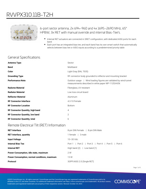
6-port sector antenna, 2x 694–960 and 4x 1695–2690 MHz, 65°HPBW, 3x RET with manual override and internal Bias-Tee's.Internal RET actuators are connected in SRET configuration, with dedicated AISG ports for eachbandEach port has an integrated bias tee, and each band has its own smart switch that automaticallyselects between bias tee or AISG inputs according to a predetermined priority tableGeneral SpecificationsAntenna Type SectorBand MultibandColor Light Gray (RAL 7035)Grounding Type RF connector body grounded to reflector and mounting bracket Performance Note Outdoor usage | Wind loading figures are validated by wind tunnelmeasurements described in white paper WP-112534-ENRadome Material Fiberglass, UV resistantRadiator Material Low loss circuit boardReflector Material AluminumRF Connector Interface 4.3-10 FemaleRF Connector Location BottomRF Connector Quantity, high band4RF Connector Quantity, low band2RF Connector Quantity, total6Remote Electrical Tilt (RET) InformationRET Interface8-pin DIN Female | 8-pin DIN MaleRET Interface, quantity 1 female | 3 maleInput Voltage10–30 VdcInternal Bias Tee Port 1 | Port 2 | Port 3 | Port 4 | Port 5 | Port 6Internal RET High band (2) | Low band (1)Power Consumption, idle state, maximum 2 WPower Consumption, normal conditions, maximum13 WProtocol3GPP/AISG 2.0 (Single RET)15Page ofPage of 25DimensionsWidth 350 mm | 13.78 in Depth 208 mm | 8.189 in Length2533 mm | 99.724 in Net Weight, without mounting kit33.2 kg | 73.193 lbArray LayoutPort ConfigurationElectrical SpecificationsImpedance50 ohmOperating Frequency Band1695 – 2690 MHz | 694 – 960 MHzPolarization±45°Total Input Power, maximum1,000 W @ 50 °CElectrical SpecificationsFrequency Band, MHz694–790790–890890–9601695–18801850–19901920–21802300–2690Gain, dBi16.316.716.917.517.918.118.669676462606261Beamwidth, Horizontal,degreesBeamwidth, Vertical, degrees10.18.98.27.67.1 6.6 5.5Beam Tilt, degrees0–100–100–100–100–100–100–10USLS (First Lobe), dB18181818181818Null Fill, dB-22-22-22-22-22-22-22Front-to-Back Ratio at 180°,29323133423839dB28282830303030Isolation, Cross Polarization,dBIsolation, Inter-band, dB30303030303030VSWR | Return loss, dB 1.5 | 14.0 1.5 | 14.0 1.5 | 14.0 1.5 | 14.0 1.5 | 14.0 1.5 | 14.0 1.5 | 14.0PIM, 3rd Order, 2 x 20 W, dBc-150-150-150-150-150-150-150200200200175175175175Input Power per Port at 50°C,maximum, watts35Page ofElectrical Specifications, BASTAFrequency Band, MHz694–790790–890890–9601695–18801850–19901920–21802300–2690 Gain by all Beam Tilts,average, dBi1616.516.817.117.617.818.2Gain by all Beam TiltsTolerance, dB±0.5±0.2±0.1±0.4±0.4±0.3±0.5Gain by Beam Tilt, average, dBi 0 ° | 16.05 ° | 16.010 ° | 15.90 ° | 16.55 ° | 16.510 ° | 16.50 ° | 16.95 ° | 16.910 ° | 16.80 ° | 17.05 ° | 17.110 ° | 17.20 ° | 17.65 ° | 17.610 ° | 17.60 ° | 17.85 ° | 17.810 ° | 17.80 ° | 18.35 ° | 18.310 ° | 18.1Beamwidth, HorizontalTolerance, degrees±1±1.1±1.8±2.5±1.4±2.5±5.6Beamwidth, VerticalTolerance, degrees±0.7±0.4±0.3±0.4±0.3±0.5±0.4USLS, beampeak to 20° abovebeampeak, dB18181818181818Front-to-Back Total Power at180° ± 30°, dB26262527292729CPR at Boresight, dB15161619202120CPR at Sector, dB12121413121211Mechanical SpecificationsWind Loading @ Velocity, frontal445.0 N @ 150 km/h (100.0 lbf @ 150 km/h)Wind Loading @ Velocity, lateral379.0 N @ 150 km/h (85.2 lbf @ 150 km/h)Wind Loading @ Velocity, maximum942.0 N @ 150 km/h (211.8 lbf @ 150 km/h)Wind Loading @ Velocity, rear472.0 N @ 150 km/h (106.1 lbf @ 150 km/h)Wind Speed, maximum241 km/h (150 mph)Packaging and WeightsWidth, packed456 mm | 17.953 inDepth, packed357 mm | 14.055 inLength, packed2834 mm | 111.575 inWeight, gross50 kg | 110.231 lbRegulatory Compliance/CertificationsAgency ClassificationCHINA-ROHS Above maximum concentration valueISO 9001:2015Designed, manufactured and/or distributed under this quality management systemROHS Compliant/ExemptedPage of45UK-ROHSCompliant/ExemptedIncluded ProductsT-029-GL-E–Adjustable Tilt Pipe Mounting Kit for 2.362"-4.5" (60-115mm) OD round members for panelantennas. Includes 2 clamp sets.* FootnotesPerformance Note Severe environmental conditions may degrade optimum performancePage of55。
CL7205B超高频天线用户手册说明书

CL7205B 超高频天线用户手册深圳市鸿陆技术有限公司欢迎您成为鸿陆RFID射频识别产品的用户!非常高兴您选择了本款CL7205B超高频天线,希望我们的产品能为您的工作带来便利目录一、技术规格 (1)1.1产品特点 (1)1.2主要功能及技术性能 (1)1.2.1 电气性能 (1)1.2.2 机械性能 (1)二、示意图 (2)2.1结构外形尺寸 (2)三、天线性能 (3)3.1驻波 (3)3.2表面磁场分布..................................................................................................................................................... 错误!未定义书签。
3.3方向图 (4)四、实物图 (5)五、安装 (6)六、常见故障 (9)6.1日常维护 (9)6.2常见故障分析及解决 (9)6.3存储要求 (9)七、售后服务 (10)一、技术规格1.1 产品特点CL7205B是一款高性能超高频天线,工作频段包含920MHz~925MHz、902MHz~928MHz、865MHz~868MHz、840MHz~845MHz。
具有尺寸小、驻波低、圆极化好等特点,该天线是一款通用型天线,适合中距离室内环境使用。
1.2 主要功能及技术性能1.2.1 电气性能✧频段:840MHz~960MHz,✧远场增益:6dBi✧输入功率:10W(最大)✧驻波:1.5:1✧极化方式:圆极化✧接口:SMA公头,从外壳侧面出1.2.2 机械性能✧天线尺寸:164mm*164mm*24.6mm✧包装尺寸:259mm*182*81mm✧单箱数量:2个✧重量:1.32kg✧工作温度:-20℃~+70℃✧储存温度:-40℃~+80℃✧材质:ABS、铝✧颜色:乳白色二、示意图2.1 结构外形尺寸CL7205B超高频天线体积参数为164mm×164mm×24.6mm(不含附件)三、天线性能3.1驻波图1 天线驻波测试图3.2方向图图1 天线方向图四、实物图五、安装CL7205B型天线可通过自带支架或用户自配支架安装在钢架结构或支柱上,通过同轴线与读写器连接。
高频双凸缸抗干扰天线Drg-118G技术手册说明书
TECHNICAL MANUAL FOR Advanced Antennas DRG-118G Horn Antenna1 - 18 GHz Double Ridged Horn AntennaADVANCED ANTENNAS10401 Roselle StreetSan Diego, CA 92121(800) 404-2832TABLE OF CONTENTSPage SECTION 1. GENERAL DESCRIPTION (3)SECTION 2. TECHNICAL SPECIFICATIONS (6)2.1. Electrical Specifications (6)2.2. Mechanical Specifications (7)2.3. Environmental Specifications (7)2.4. Typical Data (8)SECTION 3. THEORY (29)3.1. General (29)3.2. Field Measurement (29)SECTION 4. SETUP & OPERATION (31)4.1. Setup (31)4.2. Factors Affecting Operation (31)SECTION 5. MAINTENANCE (32)SECTION 6. REPLACEABLE PARTS LIST (33)Advanced Antennas10401 Roselle Street Phone: (800) 404-2832SECTION 1.GENERAL DESCRIPTIONThe DRG-118G (DRG-118/A) is a linearly-polarized wide-band Double-Ridged Horn Antenna. The DRG-118G antenna model number is identical to the old model number DRG-118/A. It is designed to transmit or receive in the frequency band from 1.0 GHz to 18.0 GHz with low VSWR, optimum antenna factor, high gain, uniform E-Plane and H-plane radiation patterns, and high transmit power capability. The antenna may be used with its typical antenna factor characteristic (see Figure 2-3) to make approximate field strength measurements. Greater accuracy requires individual calibration. The antenna is ideally suited for EMC testing, direction finding, surveillance, and antenna gain and pattern measurements.The antenna has the advantage of small size and light weight, and it can be mounted to a tripod or flat surface using the ¼-20 tapped hole on its mounting bracket, as shown in Figures 1-1, 1-2, 1-3, and 1-4.Figure 1-1 The DRG-118GAdvanced Antennas10401 Roselle Street Phone: (800) 404-2832Advanced Antennas10401 Roselle Street Phone: (800) 404-2832Figure 1-2 The DRG-118GFigure 1-3 The DRG-118GAdvanced Antennas10401 Roselle Street Phone: (800) 404-2832Figure 1-4 DRG-118G OutlineSECTION 2. TECHNICAL SPECIFICATIONS2.1. Electrical SpecificationsFrequency Range: 1.0 GHz to 18.0 GHz.Polarization: Linear.Pattern:Unidirectional Beam in E-Plane and H-Plane (see Figures 2-4 to 2-21).3 dB Beamwidth: 35° to 20° Nominal (see Figures 2-4 to 2-21).Impedance: 50 Ohms.VSWR: 2.0 : 1 Typical (see Figure 2-1).Gain: 6.0 dBi to 14.0 dBi Typical (see Figure 2-2).Antenna Factor: 36.6 dB / m Typical (see Figure 2-3).Power Handling: 400 Watts CW.Connector: Type N Female.Advanced Antennas10401 Roselle Street Phone: (800) 404-28322.2. Mechanical SpecificationsAntenna Dimensions (Maximum):Length: 7.85” (19.9 centimeter).Width: 9.50” (24.1 centimeter).Height: 5.63” (14.3 centimeter).Antenna Weight: 3.8 lbs (1.7 kg).Mounting: ¼-20 threaded hole for tripod mount.Material: Aluminum, Brass, Stainless Steel, & Black Phenolic.Finish: White Enamel, Gold Iridite.2.3. Environmental SpecificationsHumidity: Up to 100%.Advanced Antennas10401 Roselle Street Phone: (800) 404-2832Advanced Antennas10401 Roselle Street Phone: (800) 404-28322.4. Typical DataFigure 2-1 DRG-118G Typical VSWR PlotFigure 2-2 DRG-118G Typical Gain PlotAdvanced Antennas10401 Roselle Street Phone: (800) 404-2832Figure 2-3 DRG-118G Typical AFE PlotAdvanced Antennas10401 Roselle Street Phone: (800) 404-2832Advanced Antennas10401 Roselle Street Phone: (800) 404-2832FREQ: 1.000 GHZPOLARIZATION: LinearFigure 2-4 DRG-118G Typical E-Plane Pattern at 1 GHzAdvanced Antennas10401 Roselle Street Phone: (800) 404-2832FREQ: 2.000 GHZPOLARIZATION: LinearFigure 2-5 DRG-118G Typical E-Plane Pattern at 2 GHzAdvanced Antennas10401 Roselle Street Phone: (800) 404-2832FREQ: 3.000 GHZPOLARIZATION: LinearFigure 2-6 DRG-118G Typical E-Plane Pattern at 3 GHzAdvanced Antennas10401 Roselle Street Phone: (800) 404-2832FREQ: 4.000 GHZPOLARIZATION: LinearFigure 2-7 DRG-118G Typical E-Plane Pattern at 4 GHzAdvanced Antennas10401 Roselle Street Phone: (800) 404-2832FREQ: 5.000 GHZPOLARIZATION: LinearFigure 2-8 DRG-118G Typical E-Plane Pattern at 5 GHzAdvanced Antennas10401 Roselle Street Phone: (800) 404-2832FREQ: 6.000 GHZPOLARIZATION: LinearFigure 2-9 DRG-118G Typical E-Plane Pattern at 6 GHzAdvanced Antennas10401 Roselle Street Phone: (800) 404-2832FREQ: 7.000 GHZPOLARIZATION: LinearFigure 2-10 DRG-118G Typical E-Plane Pattern at 7 GHzAdvanced Antennas10401 Roselle Street Phone: (800) 404-2832FREQ: 8.000 GHZPOLARIZATION: LinearFigure 2-11 DRG-118G Typical H-Plane Pattern at 8 GHzAdvanced Antennas10401 Roselle Street Phone: (800) 404-2832FREQ: 9.000 GHZPOLARIZATION: LinearFigure 2-12 DRG-118G H-Plane pattern at 9 GHzAdvanced Antennas10401 Roselle Street Phone: (800) 404-2832FREQ: 10.000 GHZPOLARIZATION: LinearFigure 2-13 DRG-118G Typical H-Plane Pattern at 10 GHzAdvanced Antennas10401 Roselle Street Phone: (800) 404-2832FREQ: 12.000 GHZPOLARIZATION: LinearFigure 2-14 DRG-118G Typical E-Plane Pattern at 12 GHzAdvanced Antennas10401 Roselle Street Phone: (800) 404-2832FREQ: 12.000 GHZPOLARIZATION: LinearFigure 2-15 DRG-118G Typical H-Plane Pattern at 12 GHzAdvanced Antennas10401 Roselle Street Phone: (800) 404-2832FREQ: 14.000 GHZPOLARIZATION: LinearFigure 2-16 DRG-118G Typical E-Plane Pattern at 14 GHzAdvanced Antennas10401 Roselle Street Phone: (800) 404-2832FREQ: 14.000 GHZPOLARIZATION: LinearFigure 2-17 DRG-118G Typical H-Plane Pattern at 14 GHzAdvanced Antennas10401 Roselle Street Phone: (800) 404-2832FREQ: 16.000 GHZPOLARIZATION: LinearFigure 2-18 DRG-118G Typical E-Plane Pattern at 16 GHzAdvanced Antennas10401 Roselle Street Phone: (800) 404-2832FREQ: 16.000 GHZPOLARIZATION: LinearFigure 2-19 DRG-118G Typical H-Plane Pattern at 16 GHzAdvanced Antennas10401 Roselle Street Phone: (800) 404-2832FREQ: 18.000 GHZPOLARIZATION: LinearFigure 2-20 DRG-118G Typical E-Plane Pattern at 18 GHzAdvanced Antennas10401 Roselle Street Phone: (800) 404-2832FREQ: 18.000 GHZPOLARIZATION: LinearFigure 2-21 DRG-118G Typical H-Plane Pattern at 18 GHzSECTION 3. THEORY3.1. GeneralThe DRG-118G is a linearly-polarized wide-band Dual-Ridged Horn Antenna. It is designed to transmit or receive in the frequency band from 1.0 GHz to 18.0 GHz with low VSWR, high gain, uniform E-plane and H-plane radiation patterns, and high transmit power capability. The antenna is ideally suited for EMC testing, surveillance, gain measurements, and pattern measurements.3.2. Field MeasurementThe Power gain G, relative to an isotropic antenna, and the E-Field antenna factor AFE are related byAFE (dB/m) = 20*log10f - G(dBi) - 29.78 (Equation 3-1)where f is frequency in MHz. The E-field antenna factor is the ratio of the incident E-field in volts/meter to output voltage V O of the antenna across a termination resistor of stated value. The formula given above is valid only for a 50 Ohm termination.Individually calibrated Antenna Factor curves can be provided as an option (see Figure 2-3 for typical Antenna Factor calibration data) and can be used to measure electric field strengths. To measure the electric field strength, first set up the antenna (see Section 4). The incident electric field strength seen by the antenna, denoted by E, is then determined from the voltage level V O at the receiver (when the output connector of the antenna is matched to 50 Ohms). These two quantities are related through the frequency-dependent electric field antenna factor (AFE) byE (V/M) = AFE (1/m) x V O (V). (Equation 3-2)Advanced Antennas10401 Roselle Street Phone: (800) 404-2832Converting Equation 3-2 into decibel form givesE (dB V/m) = AFE (dB/m) + V O (dB V). (Equation 3-3)An example showing the application of Equation 3-2 is given below. Assume the observed antenna output voltage at 10 GHz is V O = 7.0 microvolts (-103.1 dB V) across the 50 Ohm load at the receiver and that the antenna factor is typically as followsAFE = 38.03 dB/m,henceE (dB V/m) = 38.03 - 103.1 =-65.07 dB V/m,which is equivalent toE = 10E (dB)/20 V/m (Equation 3-3)= 10-65.07/20 = 557.83 x 10⁻⁶ V/mAdvanced Antennas10401 Roselle Street Phone: (800) 404-2832SECTION 4. SETUP & OPERATION4.1. SetupThe DRG-118G, by itself, requires no assembly. Mount the DRG-118G to a tripod or mounting bracket in the desired Polarization (Vertical or Linear) using the provided ¼-20 threaded holes on the antenna mount angle (see Figures 1-1 to 1-4). Then connect the RF connector of the DRG-118G (Type N Female) to the receiver, transmitter, or test equipment using an appropriate coaxial cable. The antenna is then ready for use. For field strength measurement instructions, see Section3.2.4.2. Factors Affecting OperationFactors affecting the antenna operation include:• the distance between the antenna and the source or receiving system,• the orientation of the horn polarization with respect to the desired polarization,• the position of the antenna with respect to any large conducting objects, and• the background noise of the environment.The source or receiving system should not be located closer than 1 meter to the DRG-118G in order for the calibrated antenna factor to be accurate.Advanced Antennas10401 Roselle Street Phone: (800) 404-2832SECTION 5. MAINTENANCELittle or no maintenance will be required if care is exercised in handling the system. The antenna itself is fabricated of aluminum, which can dent or scratch if handled in a rough manner, or if otherwise abused. However, it should be recognized that small dents and scratches usually do not alter the performance of the antenna.If the antenna fails to provide satisfactory performance, it is recommended that it should be returned to Advanced Antennas for service. Address requests for replacement parts or service to: ADVANCED ANTENNAS10401 Roselle StreetSan Diego, CA 92121(800) 404-2832Advanced Antennas10401 Roselle Street Phone: (800) 404-2832SECTION 6. REPLACEABLE PARTS LISTWhen placing orders, please include the following information: Model Number, Part Number, Serial Number, Color, and Description of the item.Example: Model Number: DRG-118GPart Number: AA-DRG-118GSerial Number: 000Color: NoneDescription: DOUBLE-RIDGED HORNANTENNA, 1 - 18 GHz There are no field-replaceable parts for the DRG-118G. Any damage that may occur to the unit will require returning the unit to Advanced Antennas for servicing. All assembly hardware is American Standard for Unified Screw Threads.Part Number DescriptionAA-DRG-118G DOUBLE RIDGED HORN ANTENNA, 1 - 18 GHzTable 6-1 DRG-118G Replaceable Parts ListAdvanced Antennas10401 Roselle Street Phone: (800) 404-2832WARRANTYAll equipment manufactured by Advanced Antennas is warranted against defects in materials and workmanship for a period of one year from the date of shipment. Advanced Antennas will repair or replace any defective item or material if notified within the warranty period.You will not be charged for warranty services performed at our factory. You must, however, prepay inbound shipping costs. This warranty does not apply to:a) Products damaged during shipment EX-WORKS our plantb) Products which have been improperly installedc) Products which have been improperly used (operated outside the specification)d) Products which have been improperly maintainede) Consumable items such as batteries, lamps, fuses, customer replaceable solid-statecomponents, etc.f) Products which have been modifiedg) Normal wear of materialsh) Calibration of productsAny warranties or guarantees, whether expressed or implied, that are not specifically set forth herein, will not be considered applicable to any equipment sold or otherwise furnished by Advanced Antennas. Under no circumstances does Advanced Antennas recognize or assume any liability for any loss, damage or expense arising either directly or indirectly from the use or handling of products manufactured by Advanced Antennas, or any inability to use them separately or in combination with other equipment or materials.The warranty is void if items are shipped outside the U.S.A. without prior knowledge of Advanced Antennas.A return authorization is required for repairs under warranty. Please contact Advanced Antennasfor additional information.TM-DRG118G-042020Advanced Antennas10401 Roselle Street Phone: (800) 404-2832。
R-6000短波天线手册
LOCATION Although the R6000 will operate in almost any location, it will perform best if it is mounted vertically and located in the clear away from surrounding objects such as buildings, trees, power lines, towers, guy wires, antennas and metallic objects. The R6000 should not be attached to a ground radial system. Failure to heed these points will possibly degrade performance, detune the antenna and increase VSWR.
ADJUSTMENT The dimensions in Chart A normally allow proper operation on all the bands. However, some variations may occur from one location to another. Adjustments must be made from the bottom of the antenna to the top. Adjusting the antenna from top to bottom will not work. This is because the settings at the top are severely affected by the adjustments at the bottom.
H3C天线手册ANT-2503C吸顶天线-5PW100-整本手册
H3C天线手册ANT-2503C吸顶天线-5PW100-整本手册目录1技术参数 (1)2安全注意事项 (4)3安装注意事项 (5)4选择安装位置 (5)5天线安装 (5)5.1 安装工具 (5)5.2 吸顶安装 (5)5.3 射频线缆要求 (6)H3C天线手册 ANT-2503C 吸顶天线1 技术参数ANT-2503C天线主要用于室内应用场景,通过N型接头连接到H3C室内型AP的2.4GHz或5GHz的射频接口。
图1-1天线外观图表1-1技术参数天线型号 ANT-2503C频率范围(MHz) 2400~2500 5150~5850带宽(MHz) 1007004.5增益(dBi) 2.5水平面波瓣宽度(度) 360垂直面波瓣宽度(度) 50驻波比≤2.0输入阻抗(?) 50极化方式垂直最大功率(W) 50接头型号 N-型阴头天线尺寸(mm)φ124×47天线重量(kg) 0.15工作温度(℃) -40℃~+60℃安装方式螺母紧固下图为水平方向图和垂直方向图的天线远场方向图。
图1-2 2.4GHz水平面方向图图1-45GHz水平面方向图2 安全注意事项天线安装具有一定的危险性,请在操作前阅读下面的安全注意事项,以免误操作造成伤亡。
请不要把天线安装在靠近电源、路灯、供电箱或者其他容易导致触电的地方。
安装时请务必注意不要接触电线,否则可能引起严重的伤亡。
请尽可能选择安全的安装位置,远离电源线和其他线缆,以免触电或者被线缆缠绕导致的危险。
请尽量避免一个人安装天线,尽量事先与其他安装人员共同确认安装位置和安装步骤。
在需要竖立抱杆的情况下,请注意多人配合,以免受伤。
安装天线时请务必注意:禁止站立在金属梯子上安装天线,不要在潮湿或者刮大风的天气安装天线,同时请穿着适合安装天线的服装和可以绝缘的橡胶底的鞋子,并佩戴橡胶手套。
如果天线、射频电缆或者其他安装附件从高处掉落,请尽快躲避开,以免触电和被掉落的物品砸伤。
CommScope 54-port 双频扇形天线数据手册说明书
4-port sector antenna, 2x 790–960 and 2x 1710–2690 MHz, 65° HPBW,RET compatibleUtilizes AccuRET® actuator(s) on the back of the antennaOBSOLETEThis product was discontinued on: March 31, 2023Replaced By:4P-2L2M-B24-port sector antenna, 2x 694–960 and 2x 1695–2690 MHz, 65° HPBW, 2x RETGeneral SpecificationsAntenna Type SectorBand MultibandColor Light Gray (RAL 7035)Grounding Type RF connector inner conductor and body grounded to reflector andmounting bracketPerformance Note Outdoor usage | Wind loading figures are validated by wind tunnelmeasurements described in white paper WP-112534-ENRadome Material Fiberglass, UV resistantRadiator Material AluminumRF Connector Interface7-16 DIN FemaleRF Connector Location BottomRF Connector Quantity, high band2RF Connector Quantity, low band2RF Connector Quantity, total4Remote Electrical Tilt (RET) InformationModel with Factory Installed AISG 2.0 Actuator CV65BSX-2X2DimensionsWidth301 mm | 11.85 inDepth181 mm | 7.126 inLength1974 mm | 77.717 in15Page ofPage of 25Net Weight, without mounting kit17.9 kg | 39.463 lbArray LayoutPort ConfigurationElectrical SpecificationsImpedance50 ohmOperating Frequency Band1710 – 2690 MHz | 790 – 960 MHzPolarization±45°Electrical SpecificationsFrequency Band, MHz790–896870–9601710–18801850–19901920–21802300–25002500–2690Gain, dBi15.615.617.417.718.11818.2Beamwidth, Horizontal,63627166675758degreesBeamwidth, Vertical, degrees10.59.7 5.6 5.35 4.3 4.1Beam Tilt, degrees0–100–102–122–122–122–122–12USLS (First Lobe), dB14161516161516Front-to-Back Ratio at 180°,29292825232930dBCPR at Boresight, dB23222020201618CPR at Sector, dB1010977 5.3728282828282828Isolation, Cross Polarization,dBIsolation, Inter-band, dB303030303030301.5 | 14.0 1.5 | 14.0 1.5 | 14.0 1.5 | 14.0 1.5 | 14.0 1.5 | 14.0 1.5 | 14.035Page ofVSWR | Return loss, dB 1.5 | 14.0 1.5 | 14.0 1.5 | 14.0 1.5 | 14.0 1.5 | 14.0 1.5 | 14.0 1.5 | 14.0 PIM, 3rd Order, 2 x 20 W, dBc-150-150-150-150-150-150-150Input Power per Port,maximum, watts350350350350350300300 Electrical Specifications, BASTAFrequency Band, MHz790–896870–9601710–18801850–19901920–21802300–25002500–2690 Gain by all Beam Tilts,average, dBi15.315.417.217.517.617.718Gain by all Beam TiltsTolerance, dB±0.5±0.4±0.3±0.3±0.5±0.6±0.4Gain by Beam Tilt, average, dBi 0 ° | 15.45 ° | 15.410 ° | 15.10 ° | 15.45 ° | 15.510 ° | 15.12 ° | 17.17 ° | 17.312 ° | 17.22 ° | 17.47 ° | 17.612 ° | 17.42 ° | 17.57 ° | 17.712 ° | 17.62 ° | 17.67 ° | 17.912 ° | 17.52 ° | 17.87 ° | 18.112 ° | 17.7Beamwidth, HorizontalTolerance, degrees±2.7±1.9±4.6±2.4±2.4±3.5±4.5Beamwidth, VerticalTolerance, degrees±0.8±0.6±0.3±0.3±0.3±0.2±0.2USLS, beampeak to 20° abovebeampeak, dB16161617171618Front-to-Back Total Power at180° ± 30°, dB25252624222224CPR at Boresight, dB25252021201618CPR at Sector, dB1111129957Mechanical SpecificationsWind Loading @ Velocity, frontal306.0 N @ 150 km/h (68.8 lbf @ 150 km/h)Wind Loading @ Velocity, lateral253.0 N @ 150 km/h (56.9 lbf @ 150 km/h)Wind Loading @ Velocity, maximum589.0 N @ 150 km/h (132.4 lbf @ 150 km/h)Wind Loading @ Velocity, rear310.0 N @ 150 km/h (69.7 lbf @ 150 km/h)Wind Speed, maximum241 km/h (150 mph)Packaging and WeightsWidth, packed441 mm | 17.362 inDepth, packed337 mm | 13.268 inLength, packed2108 mm | 82.992 inWeight, gross34.6 kg | 76.28 lbRegulatory Compliance/CertificationsPage of45Agency ClassificationCE Compliant with the relevant CE product directivesISO 9001:2015Designed, manufactured and/or distributed under this quality management system REACH-SVHC Compliant as per SVHC revision on /ProductCompliance ROHS CompliantUK-ROHSCompliantIncluded ProductsBSAMNT-OFFSET–Forward Offset Pipe Mounting Kit for 4.5 in (114.3 mm) OD roundmembers* FootnotesPerformance Note Severe environmental conditions may degrade optimum performancePage of55。
- 1、下载文档前请自行甄别文档内容的完整性,平台不提供额外的编辑、内容补充、找答案等附加服务。
- 2、"仅部分预览"的文档,不可在线预览部分如存在完整性等问题,可反馈申请退款(可完整预览的文档不适用该条件!)。
- 3、如文档侵犯您的权益,请联系客服反馈,我们会尽快为您处理(人工客服工作时间:9:00-18:30)。
60
7
水平 470×175×60 1.8
TDJ-5158EA23
TDJ-5158GA×2
TDJ-5158BKT-C
TDJ-5158BKT1
TDJ-5158BKC45/60/90
TDJ-5158K20
佛山市健博通电讯实业有限公司
5.1GHz,5.5GHz,5.8GHz 抛物面天线
型号
水平面 垂直面
频率范围(MHz) 增益(dBi)
5100-5850
18
20
20
垂直 190×216×50 1.1
TDJ-5158BKR
5150-5850
20
15
15
垂直或水平 261×261×35 1.1
TDJ-5158BKR×2
5150-5850
≥18
17
17
垂直和水平 261×261×35 1.15
TDJ-5158BKR×2A 5150-5850
波瓣宽度(°) 波瓣宽度(°)
TDJ-5158LX-R
5150-5850
11
55
55
右旋圆极化 Φ100×130 0.56
4.9GHz 公共安全系统板状天线
型号
水平面 垂直面
频率范围(MHz) 增益(dBi)
极化方式 尺寸(mm) 重量(kg)
波瓣宽度(°) 波瓣宽度(°)
TDJ-4958K/G/I/J 系列 4900-5850 19/18/17/15 45/60/90/120
TDJ-5158BKF-Y1
5725-5850
14
43
30
垂直 125×97×30 0.22
TDJ-5158BKC45/60/90 5100-5850
16/15/14 45/60/90
16
垂直 210×190×50 1.1
TDJ-5158BKT1
5150-5850
≥23
11
11
垂直或水平 306×306×25 1.4
TQJ-5500BII 系列 TQJ-5158MOD×3
佛山市健博通电讯实业有限公司
5.1GHz,5.5GHz,5.8GHz 壁挂天线
型号
水平面 垂直面
频率范围(MHz) 增益(dBi)
极化方式 尺寸(mm) 重量(kg)
波瓣宽度(°) 波瓣宽度(°)
TDJ-5158BKF9
5150-5850
9.5
27.5
6
6
垂直和水平
Φ600
5
TDJ-5800P9×2
5725-5850
31
4
4
垂直和水平
Φ900
10
TDJ-5800SPL4
5725-5850
24
9
12
垂直或水平 300×400
1.4
TDJ-5800SPL6
5725-5850
27
6
9
垂直或水平 400×600
2.4
TDJ-5800SPL9
5725-5850
8
360
16
垂直
Φ20×330
0.2
TQJ-5800AD10
5725-5850
10
360
10
垂直
Φ20×430
0.35
TQJ-5800AD12
5725-5850
12
360
7
垂直
Φ20×550
0.55
TQJ-5800AT
5725-5850
13
360
6
垂直
700
0.6
TQJ-5800H9
5725-5850
10
13
垂直或水平 300×400
1.4
TDJ-5100SPL6
5150-5350
25.5
6.5
10
垂直或水平 400×600
2.4
TDJ-5100SPL9
5100-5350
29
5
7
垂直或水平 600×900
4.5
TDJ-5800SPL9 TDJ-5800P6×2
TDJ-5500P4
TDJ-5500SPL4 TDJ-5800P9
73
32
垂直
125×97×30 0.21
TDJ-5158BKF90 5150-5850
7.3
90
31
垂直
125×97×30
0.2
TDJ-5158BKE
5100-5850
12
45
35
垂直
88×70×120 0.08
TDJ-5158BKF
5100-5850
14
43
30
垂直 145×97×38 0.52
5.1GHz,5.5GHz,5.8GHz 车台天线
12
360
7
垂直
Φ20×580 0.57
TQJ-5100H13
5150-5250
13
360
7
水平
510×42×22
0.35
TQJ-5158MOC×3 5150-5850
4.5
/
/
垂直
148×60
0.4
TQJ-5158MOD×3 5150-5850
4.5
/
/
垂直
Ф148×50
0.35
TQJ-5500AD 系列 TQJ-5800H9
27
8
8
垂直或水平
Φ600
5
TDJ-4900P9
4900-5000
30.5
5
5
垂直或水平
Φ900
10
TDJ-4900SPL4 4900-5000
22
10
13
垂直或水平 300×400
1.4
TDJ-4900SPL6 4900-5000
佛山市健博通电讯实业有限公司
5.1GHz,5.5GHz,5.8GHz 全向天线
型号
水平面 垂直面
频率范围(MHz) 增益(dBi)
极化方式 尺寸(mm) 重量(kg)
波瓣宽度(°) 波瓣宽度(°)
TQJ-5800AD6
5725-5850
6
360
25
垂直
Φ20×260
0.18
TQJ-5800AD8
5725-5850
型号
频率范围(MHz)
增益(dBi) 极化方式
TQC-5500CE
5150-5850
5
垂直
尺寸(mm)
205
重量(kg)
0.1
5.1GHz,5.5GHz,5.8GHz 终端机天线
水平面
垂直面
型号 频率范围(MHz) 增益(dBi)
极化方式 尺寸(mm) 重量(kg)
波瓣宽度(°) 波瓣宽度(°)
TQX-5158L
30
4
6
垂直或水平 600×900
4.5
TDJ-5800P12B
5725-5850
34.5
3
3
垂直或水平 Φ1200
28.5
TDJ-5500P4
5470-5725
23.5
9
9
垂直或水平
Φ400
3
TDJ-5500P6
5470-5725
28.5
6
6
垂直或水平
Φ600
5
TDJ-5500P9
5470-5725
1.4
TDJ-5158SPL6
5150-5850
26.5
6
9
垂直或水平 400×600
2.4
TDJ-5158SPL9
5150-5850
29.5
4
6
垂直或水平 600×900
4.5
TDJ-5100P12B
TDJ-5158P4
TDJ-5158P6A×2
TDJ-5158PP8A
TDJ-5158P9A×2
TDJ-5158P12A
极化方式 尺寸(mm) 重量(kg)
波瓣宽度(°) 波瓣宽度(°)
TDJ-5800P4
5725-5850
24
9
9
垂直或水平
Φ400
3
TDJ-5800P6
5725-5850
29
6
6
垂直或水平
Φ600
5
TDJ-5800P9
5725-5850
32.5
6
6
垂直或水平
Φ900
10
TDJ-5800P6×2
5725-5850
7
垂直 455×140×35 0.7
4.9GHz 公共安全系统抛物面天线
型号
水平面 垂直面 频率范围(MHz) 增益(dBi) 波瓣宽度(°) 波瓣宽度(°) 极化方式 尺寸(mm) 重量(kg)
TDJ-4900P4
4900-5100
22.5
10
10
垂直或水平
Φ400
3
TDJ-4900P6
4900-5000
5150-5850
28.5
5
5
垂直或水平
Φ600
5.5
TDJ-5158P9A×2
5150-5850
32
3.5
3.5
垂直或水平
Φ900
10.5
TDJ-5158P12A×2 5150-5850
34
3
3
垂直或水平
Φ1200
20
TDJ-5158SPL4
5150-5850
23.5
9
12
垂直或水平 300×400