德国Posital绝对值编码器样本
绝对型编码器——单圈型
2/22绝对型编码器单圈型1) 优先型仅与法兰类型 2 一同使用。
2) 优先型仅与法兰类型 1 一同使用。
3) 只能结合接口 1 和 2。
4) 分辨率、预置值和计数方向由厂家设定。
5) 仅与接口 1 或 2 以及编码 C 共用。
6) 用于电缆连接方式,电缆材料聚氨酯 (PUR)。
具有光学传感器技术的 Sendix 5853 和 Sendix 5873 单圈编码器可实现最高达 21 位的分辨率。
由于具有电子数据表的 BiSS 接口,所以易于应用。
本系列提供特殊型号以便用于电梯技术的直接驱动。
有关更多附件信息,可在附件章节或我们的网站附件一栏 /accessories 中找到。
有关更多接插件信息,可在接线连接技术章节或我们的网站接线连接技术一栏:/connection_technology 中找到。
1) 只能结合轴K和连接方式E或F。
2) 只能结合接口 1 和 2。
3) 分辨率、预置值和计数方向由厂家设定。
4) 仅与接口 1 或 2 以及编码 C 共用。
5) 用于电缆连接方式,电缆材料聚氨酯 (PUR)。
绝对型编码器单圈型1) 电缆型:-30°C ... +75°C [-22°F ... +167°F]=2) 短路到 0 V 或输出,一次有一条通道, 采用正确的电源。
技术数据绝对型编码器单圈型匹配侧的顶视图,公头插座+V : 编码器电源 +V 直流0 V : 编码器电源接地 GND (0 V)0 V sens / +V sens : 使用编码器的传感器输出,电压可测量,并且如有必要可相应增加。
C+, C- : 时钟信号数据信号增量型输出通道 A (余弦)增量型输出通道 B (正弦)设置输入DIR : 方向输入Stat : 状态输出PH H : 插头连接器外壳(屏蔽)端子配置M12 插头,8 针 M23 插头,12 针夹紧法兰,ø 58 [2.28]法兰类型 1 和 3(显示 M23 接头的图纸)1 3 x M3, 6 [0.24] 深2 3 x M4, 8 [0.32] 深方形法兰,63.5 [2.5]法兰类型 5 和 7 (显示电缆的图纸)轴型尺寸尺寸单位 mm [inch]同步法兰,ø 58 [2.28]法兰类型 2 和 4(显示 M12 接头的图纸)1 3 x M4, 6 [0.24] 深绝对型编码器单圈型带弹簧元件的法兰,长型法兰类型 1 和 2(显示 M12 接头的图纸)轴套型尺寸尺寸单位 mm [inch]带固定连接器的法兰,ø 65 [2.56] 法兰类型 3 和 4用于固定螺丝的倾斜切圆直径 65 [2.56](显示电缆的图纸)1固定螺丝 DIN 912 M3 x 8(垫圈包含于交付产品中)2夹紧环建议扭矩 0.6 Nm带固定连接器的法兰,ø 63 [2.48] 法兰类型 5 和 6用于固定螺丝的倾斜切圆直径 63 [2.48](显示 M23 接头的图纸)1固定螺丝 DIN 912 M3 x 8(垫圈包含于交付产品中)2夹紧环建议扭矩 0.6 Nm[0,492]CBA532,19,25,3664,92,56312451°25°1:1044,811,76582,280,6115,427,7,391,090,512,7M50,31857,52,26轴套型尺寸尺寸单位 mm [inch]带固定连接器的法兰,无螺丝固定法兰类型 E 和 F(带有锥形轴K和切向电缆)1状态 LED 指示灯2设置 (SET) 按钮3建议螺丝的拧紧力矩为 (SW 4) 3 +0,5 Nm带固定连接器的法兰,ø 72 [2.83]法兰类型 G(带有锥形轴K和切向电缆)1状态 LED 指示灯2设置 (SET) 按钮3建议螺丝的拧紧力矩为 (SW 4) 3 +0,5 Nm带涨紧式连接器的法兰,ø 65 [2.56“]法兰类型 H1状态 LED 指示灯2设置 (SET) 按钮3建议螺丝的拧紧力矩为 (SW 4) 3 +0,5 Nm4建议螺丝的拧紧力矩为 (SW 2) 1 Nm。
HUENG GIESSEN绝对值SSI编码器资料
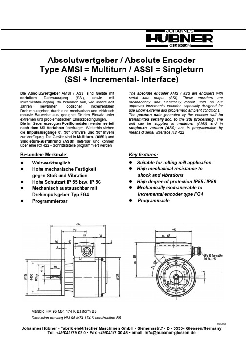
Absolutwertgeber / Absolute Encoder Type AMSI = Multiturn / ASSI = Singleturn(SSI + Incremental- Interface)Die Absolutwertgeber AMSI / ASSI sind Geräte mit seriellem Datenausgang (SSI), sowie mit Inkrementalausgang. Sie zeichnen sich, wie unsere seit Jahren bewährten, optischen inkrementalen Drehimpulsgeber, durch eine mechanisch und elektrisch robuste Bauweise aus, geeignet für den Einsatz unter extremen und problematischen Einsatzbedingungen.Die im Geber erzeugten Positionsdaten werden seriell nach dem SSI Verfahren übertragen. Weiterhin stehen die Impulsausgänge 0°, 90° 0°invers und 90° invers zur Verfügung. Die Geräte sind in Multiturn- (AMSI) und Singleturn-ausführung (ASSI) lieferbar und können über eine RS 422 - Schnittststelle programmiert werdenThe absolute encoder AMS / ASS are encoders with serial data output (SSI). These encoders are mechanically and electrically robust units as our approved incremental encoder, especially designed for use under extreme and problematic ambient conditions.The position data generated by the encoder will be transmitted serially acc. to the SSI processing. The unit can be supplied in multiturn (AMS) and in singleturn version (ASS) and is programmable by means of serial interface RS 422Besondere Merkmale: WalzwerktauglichHohe mechanische Festigkeit gegen Stoß und VibrationHohe Schutzart IP 55 bzw. IP 56 Mechanisch austauschbar mit Drehimpulsgeber Typ FG4ProgrammierbarKey features:Suitable for rolling mill application High mechanical resistance toshock and vibrationsHigh degree of protection IP55 / IP56 Mechanically exchangeable toincremental encoder type FG4ProgrammableMaßbild HM 95 M54 174 K Bauform B5Dimension drawing HM 95 M54 174 K construction B505/2001Elektrische Daten / Electrical data AMS = Multiturn / ASS = SingleturnVersorgungsspannung U B:+12V ... + 30V DCAuflösung AMS:max. 12 bit (4096 Schritte/U)max. 12 bit (4096 Umdrehungen)Auflösung ASS:max. 12 bit (4096 Schritte/U)SSI-SchnittstelleTakteingang OptokopplerSignalamplitude5VEingangsstrom 6mATaktfrequenz80 kHz-1 MHzAnzahl Takte/Übertragung AMS25Anzahl Takte/Übertragung ASS13Zeit zwischen Übertragungszyklenohne Datenwiederholung >30 µsmit Datenwiederholung<20 µsDatenausgang: RS422Steuer - Eingänge OptokopplerV/R, Z, SELSignalamplitude(5...30)VEingangsstrom 6mA Fehlerausgang:Signalamplitude ca. U BAusgangsstrom 50mA Inkrementalausgänge (Option):0°, 0° invers, 90°, 90° inversSignalamplitude ca. U BAusgangsstrom 50mA Programmierein - und ausgangRS 4228 bit, 1 Stopbit, 9600 BaudProgrammierbare FunktionenNullpunkt 1 und 2 setzenBitbreite für Multiturn- und SingleturnbereichOffset 1 und 2 setzenAusgabecode binär/grayIdentwortProgrammierdatum lesen Supply voltage U B:+ 12 V ... +30 V DCResolution AMS:max. 12 bit (4096 steps/rev.)max. 12 bit (4096 revolutions)Resolution ASS:max. 12 bit (4096 steps/rev.)SSI-interfaceClock input:opto couplerSignal amplitude: 5 VInput current: 6 mAClock frequency:80 kHz-1 MHzClock rate/transmission AMS:25Clock rate/transmission ASS:13Time between transmission cycleswithout data repetition> 30µswith data repetition<20 µsData output:RS 422 Control Inputs opto coupler V/R, Z, SELSignalamplitude(5...30)V Input current: 6 mAError output:Signal amplitude approx. U Boutput current50 mA Incremental Outputs (option):0°, 0° invers, 90°, 90° inversSignal amplitude approx. U B.output current50 mA Programm input and outputRS 4228 bit, Stopbit, 9600 Baud Programmable functionsSetting of zero point 1 + 2Bits for multiturn and singleturn rangeSetting of offset 1 + 2Output code binary/grayIdentificationReading of programming dateDatenübertragung:Die Datenübertragung erfolgt nach dem SSI - Verfahren (Serial Synchronous Interface). Dabei werden dem Geber an den Eingänge …CLCK“ und …CLCKG“(invertiert) über einen Optokopplereingang zur galvanischen Trennung Impulspakete mit 25Taktimpulsen AMS bzw. 13 Taktimpulsen (ASS)zugeführt und synchron hierzu 25 Datenbits (AMS) bzw.13 Datenbits (ASS) über eine RS 422 - Schnittstelle an dem Ausgang …DATA“ und invertiert an dem Ausgang …DATAG“ ausgegeben.Der Ruhepegel des Taktsignals liegt normal auf HIGH.Die erste fallende Flanke übernimmt die Geberstellung von den Codescheiben. Danach wird mit der steigenden Flanke von Takt 1 das erste zu übertragende Bit dem Geberausgang zugeführt, um mit der fallenden Flanke von Takt 1 vom empfangenden Gerät übernommen zu werden. Dieser Vorgang wird bis zum Takt 25 (AMS)bzw. Takt 13 (ASS) wiederholt und auf diese Weise alle Datenbits übergeben.Der Datentransfer wird durch eine steigende Flanke am Takteingang beendet. Im normalen Betrieb wird der Ausgang nach ca. 25 µs wieder auf HIGH-Pegel gesetzt und dem anfordernden Gerät die Bereitschaft des Gebers für eine erneute Datenübertragung signalisiert.Data transmission:Data transmission is effected acc. to SSI processing (Serial Synchonous Interface). This means the encoder input …CLCK“ and CLCKG“ (inverted) will be supplied with sets of 25 (AMS ) or 13 clockpulses (ASS) through an opto coupler input for electrical isolation.Synchroneously 25 data bits (AMS) or 13 data bits (ASS) will be available at the output …DATA“ and inverted signals at the ouput …DATAG“ through Interface RS422.The inactive level of clock signal is normally set at HIGH.On first falling edge the encoder position will be read from the code discs. The first transmission bit will then be supplied to the encoder output with the rising edge of clock 1 enabling the receiver unit to read the transmission bit with the falling edge of clock 1. This procedure will be repeated up to clock 25 (AMS) or clock 13 (ASS) and in this manner all data bits will be transmitted.Data transmission will end at rising edge of clock input.In normal operation the output will be set to level …HIGH“after approx. 25 µs and readyness for next data transmission will be indicated to the receiver unit.AMS n = 25 Impulse/Takteingang Clock inputDatenausgang Data OutputWird innerhalb von 20µs eine erneute Datenabfrage gestartet, so erfolgt keine Datenübernahme von den Codescheiben. es werden dann die Daten aus dem vorhergehenden Transferzyklus noch einmal über-tragen(Datenwiederholung).If a new data transfer is started within 20 µs, no data reading from the code discs will be made but data of the previous cycle will be transmitted again (data repetition).Takt ClockVerzögerung für Datenwiederholung Delay fordata repetitionDatenausgang Data output ohne Datenwiederholung without data repetitionmit Datenwiederholung with data repetitionDer Taktfrequenzbereich erstreckt sich von 80kHz bis 1MHz. Bei zu kleiner Taktfrequenz (< 80 kHz) erfolgt keine Datenübertragung.The clock frequency range is from 80 kHz up to 1 MHz. If clock frequency is too low (< 80 kHz) no data transmission will be possible.Übertragung nach dem TannenbaumformatDas Ausschieben der Daten erfolgt in der Reihenfolge Multiturn - Singleturn, das höchstwertigste Bit zuerst. Es ist möglich, die Bitanzahl sowohl für den Multiturnbereich, als auch für den Singleturnbereich zu reduzieren. Dabei ändert sich die Übertragungslänge nicht. Die durch die Reduzierung betroffenen Bits werden lediglich mit Low-Pegel aufgefüllt. Die Anzahl der Bits kann für die beiden Bereiche auch unterschiedlich programmiert werden.Transmission to tree formatData output will be made in the sequence Multiturn -Singleturn and the most significant bit (MSB) at first. It is possible to reduce the number of bits for the Multiturn range as well as for the Singleturn range. Transmission period for both ranges will not change. The bits affected by the reduction will be set to low level. Programming of bit rate for Multiturn and Singleturn range can vary from each other.252010155126409620481024512512128256256128131051Übertragung nach dem Tannenbaumformat ASSTransmission to tree format ASS512128256steps/rev.A C H T U N GDie Anschlüsse …CLCK“ und …CLCKG“(Takteingang) müssen beide mit den entsprechenden Signalen verbunden werden.Ein Vertauschen führt zu Fehlaus-lesungen.Attention:The connections …CLCKG“ + …CLCKG“(clock input) have to be connected to the corresponding signals.Wrong connection will cause errror of data reading.FehlermeldungAn dem Ausgang …ERR wird ein Signal ausgegeben, welches das einwandfreie Arbeiten des Absolutwertgebers wie folgt anzeigt: im fehlerfreien Zustand wird an …ERR“ ein HIGH-Pegel angezeigt. Ein LOW an …ERR“ signalisiert das nicht einwandfreie Arbeiten des SSI-Gebers. Dieses Signal wird erzeugt während der Einschaltroutine des Gerätes und wenn während des Programmierprozesses die Ausgabe der SSI-Daten zeitlich beeinflußt werden. Bei Störung der optischen Wegstrecken für die Codescheibenabtastung erscheint ebenfalls eine Fehlermeldung.Steuereingang V/RDurch Anlegen einer Gleichspannung an die KlemmeV/R wird die Zählrichtung auf LINKS eingestellt. 0 V oder kein Anschluß bedeuten Zählrichtung RECHTSSteuereingang ZMit einem Impuls von ca. 1s Länge ( +5V (30V)können in Abhängigkeit von dem Pegel am Eingang SEL zwei unterschiedliche Nullpunkte von der jeweils aktuellen Geberposition übernommen werden. Durch die Pegeleinstellung an SEL (HIGH oder LOW) können dann die beiden Nullpunkte angewählt werden.Steuereingang SELEin LOW-Pegel wählt den Nullpunkt 1, ein HIGH-Pegel Nullpunkt 2 an, unabhängig davon, ob letztere durch einen Impuls an Klemme Z oder per Programmierungübernommen wurden. Offset 1 oder Offset 2 werden, wenn vorher programmiert, in gleicher Weise aktiviert. Programmierbare FunktionenDer Geber ist über eine RS 422 - Schnittstelle von einem PC (Laptop) programmierbar. Die Einstellparameter werden nichtflüchtig im Geber gespeichert und sind auch nach Stromausfall wieder verfügbar. Es sind folgende Funktionen programmierbar:Nullpunkt 1 und 2 (in Abhängigkeit von dem Pegel an dem Eingang …SEL“)Bitbreite für Multiturn- und Singleturnbereich (Tannenbaumformat)Offset 1 und 2 (in Abhängigkeit von demPegel an dem Eingang …SEL“)Ausgangscode binär / grayIdentwortProgrammierdatum lesenStandardeinstellungAlle Einstellparameter, mit Ausnahme der für Nullpunkte und Standardeinstellung, können aus dem Geber ausgelesen und auf einer Diskette gespeichert werden.Error indicationA signal indicating correct operation of the encoder will be generated on the output …ERR“ as follows: while operating accurately a high level will be generated on …ERR“. Low on signal …ERR“ indicates non-correct operating of the SSI encoder. This signal will be shown during switching-on process of encoder and during programming process when SSI data output are influenced temporally. Error reading will also be indicated on misfunction of optical scanning.Control input V/RWhen the voltage will be applied to the Terminal V/R, the counting direction will be set to parameter LEFT. 0 V or no available connection means that the counting direction is set to parameter RIGHT.Control input ZWhen having a pulse of approx. 1s length(+5V ...+30V) at terminal Z two different zero points can be set to any mechanical position of the encoder which are dependent on the input level SEL. The zero points can be selected through the level (HIGH or LOW) at terminal SEL.Control input SELZero point 1 will be selected by low level and zero point 2 by high level independently of, whether the voltage will be applied to terminal Z or the setting will be made by a PC. After having defined by programming both, Offset 1 and Offset 2 can be activated.Programmable functionsProgramming of the encoder is effected by means of a PC (e.g. Laptop). Set parameters are stored involatile and are available even after a break-down caused by power failure. Following programming functions are possible:Setting of zero point 1 and 2 (dependent on level of input …SEL“)Bits for multiturn and singleturn range(tree format)Offset 1 and 2 (dependent on level ofinput …SEL“)Output code binary / grayIdentificationReading of Programming dateStandard settingAll set parameters, excluding those for zero points and standard setting, can be read from the encoder and be stored on a disk.Nullpunkt 1 und 2Die Nullpunkte 1 und 2 des Gebers können jeder mechanischen Geberposition zugeordnet werden. Hierzu wird die entsprechende Position angefahren und dann vom PC aus der Befehl zum Setzen der Nullpunkte gegeben. Hierdurch kann aufwendige Justierarbeit bei der Gebermontage erspart werden. Die Positionen für die Offsets 1 und 2 beziehen sich auf diese Punkte. Die Auswahl des aktuellen Nullpunktes erfolgt während des Betriebes über den Eingang …SEL“.Anzahl der übertragbaren BitsDie Einstellung erfolgt nach dem Tannenbaumformat und kann für den Multiturnteil von 0 .. 4095 Umdrehungen und für den Singleturnteil von 0 .. 4095 Schritten in Stufen von 2n (n= 0...12 Bit) erfolgen. Die Anzahl der Bits für die beiden Teilbereiche kann unterschiedlich gewählt werdenOffset 1 und 2Die Offsetwerte stellen eine Verschiebung der Nullpunkte dar. Sie können vom PC her numerisch beliebig im Bereich der maximalen Auflösung eingegeben, oder von der Geberstellung, bezogen auf die Nullpunkte, übernommen werden. Die Auswahl des aktuellen Offsets erfolgt während des Betriebes über den Eingang …SEL“.IdentwortMit dem Identwort kann ein beliebiger Text mit einer Länge von 8 Zeichen im Geber gespeichert werden. Dieser Text hat keinen Einfluß auf eine Geberfunktion.ProgrammierdatumBei jeder Umprogrammierung des Gebers wird das Programmierdatum auf den aktuellen Stand (PC Systemdatum) gebracht und im Geber gespeichert. AusgangscodeDie Datenausgabe ist in Binär- oder Graycode möglichStandardeinstellungMit dem Befehl Standardeinstellung werden folgende Werte eingestellt:Nullpunkt 1 und 2= Codescheiben - NullAnzahl der Bits= 24Offset 1 und 2 = 0Ausgangscode=gray Zero point 1 and 2The zero points of the encoder can be set to any mechanical position of the encoder. The corresponding points will be positioned and zero points will be set by means of a PC. Therefore there are no considerable adjustment works necessary during assembly. The positions for Offset 1 and 2 do refer to this set point. When the encoder is operating the selection of current zero points can be made through intput …SEL“.Number of transmission bitsSetting is effected according to the tree format and can be made for Multiturn range from 0... 4095 rev. and for Singleturn range from 0... 4095 steps by values of 2n (n = 0...12 Bit). The number of bits for both ranges can be individually selected.Offset 1 and 2The Offset values represent a shifting of the zero points. They can be individually set in numbers within the max. resolution range or can be read from the encoder position referring to zero point. When the encoder is operating the selection of current Offsets can be made through intput …SEL“.IdentificationAn individual text having 8 digits can be stored in the encoder. This text has no influence on the encoder functions.Programming dateProgramming date will be updated (PC system date) and stored on every programming change of encoder.Output codeData output of binary or gray code is possible.Standard settingFollowing values can be set with command standard setting:zero point 1 and 2= code disc - zeronumber of bits= 24Offset 1 and 2= 0Output code=grayProgrammierungHardwarevoraussetzungenDie Programmierung des Gebers AMS kann von einem PC (z.B. Laptop) erfolgen. Die RS 232 - Schnittstelle des PC (Com 1 oder Com 2) ist dann mit dem Adapterkabel zur Signalumsetzung auf die RS 422 - Schnittstelle des Absolutwertgebers, wie im nachfolgenden Schema gezeigt, zu verbinden. Da die geberseitigen Anschlüsse des Adapterkabels galvanisch vom PC-Port getrennt sind, muß die Betriebsspannung des Gebers auch an den Adapter angelegt werden. Die zur Programmierung notwendige Software ist unter Windows 3.1 und höher lauffähig.Softwarevoraussetzungen: Windows 3.1 oder höherProgrammingHardware RequirementsProgramming of encoder AMS can be made by means of a PC (e.g Laptop). The Interface RS 232 of a PC (Com 1or Com 2) has to be linked to the Interface RS 422 of the encoder through an adapter cable for signal conversion as shown in following scheme. As the connections of the adapter cables at encoder side are isolated from PC-Port, the encoder supply voltage must be applied to adapter also. Windows 3.1 or higher must be available for programming.Software Requirements:Windows 3.1 or higherTypenschlüssel / Type code A M S 4 K IK: Klemmleiste / Terminal box S: Hartingstecker / Harting plug M: Multiturn S: SingleturnGebertyp / encoder series I: Inkrementalausgänge (Option) Incremental outputs (opton)。
Heidenhain Endat 2.1 绝对位置编码器解码器板类型说明书

motor shaft will usually have an encoder fitted to it that provides absolute position feedback as well as feedback for closing the drive’s speed loop. This is an example of one-mark registration.
AC890 Registration boards
8902-M1 / 8903-M1
Description
The 8902-M1 and 8903-M1 feedback cards allow 1V p-p (peak-to-peak) Sin/ Cos encoders to be connected directly to the motor controller to provide highly accurate speed feedback measurement and registration.
This is typically an encoder fitted to the print cylinder that provides a once-per-revolution index pulse. This is an example of two-mark registration.
Fitted with those boards, the AC890 can achieve high-performance registration control in shaftless printing and converting applications, generally not possible in drive systems without expensive external registration controllers.
SICK绝对式编码器

R=最 小 弯 曲 半 径4 0 mm
其 它 公 差 遵 循DIN ISO-2768-mk标准
出线方式 径向出线式
径向插头式
附件 接线电缆 通孔轴套 S S I串 口 转 并 口 模 块
C1-6
技术参数
机械参数
外径 轴径 启 动 转 矩( 2 0℃) 工 作 转 矩( 2 0℃) 瞬时惯量 最大允许转速 最大角加速度 元件轴允许跳动
轴向出线式
径向插头式
轴向出线式
技术参数
机械参数
外径 轴径 启 动 转 矩( 2 0℃) 工 作 转 矩( 2 0℃) 瞬时惯量 最大允许转速 最大角加速度 元件允许轴跳动
轴承使用寿命 工作温度 存储温度 允 许 相 对 湿 度1) 抗振性能
外壳防护等级 IEC 60529
质 量5)
A R S 6 0盲 孔 型
电气参数
工作电压 工作电流
测量量程 分辨率 角度分辨率 测量误差
重复精度 角度分辨率偏差
测量值回差 响应阈值 输出接口 输出码
编 码 方 向6) “控制输入”的 "电 脉 冲"信 号 零 位 设 定 时 间7) 上电初始化时间 EMC8)
10-32V DC SSI:60mA 并 口:90mA
1圈
2...32,768(参见 订货 信息) 360°/分辨 率 2 n 分 辨率: 0.035° 非2 n 分 辨 率: 0.046° 0.005° 2 n 分 辨 率: 0.005° 非2 n 分 辨 率: 0.016°
分辨率 1...32,768
单圈绝ch 旋转编码器:模块化结构的 特别解决方案
■ 优异的性价比; ■ LED光 强 度 的 自 动 调 整 , 保 证 更长的使用寿命; ■ 通过采用“表面贴装技术”的 专用光学芯片,保证了最大程度 的可靠性; ■ 通过使用不同的轴套,可使 “孔型”(盲孔或通孔)编码器 可 配 合6mm至1 5mm及1/ 4〃 、3 / 8〃 和1/2〃 的 轴 来 使 用 ;
POSITAL编码器设置方法

POSITAL编码器设置方法1.确定编码器类型:POSITAL编码器有不同的类型,如增量式编码器和绝对式编码器。
增量式编码器可以测量转速和相对位置,而绝对式编码器可以测量绝对位置。
2.确认编码器分辨率:编码器分辨率是指编码器能够测量的最小位置变化。
它通常以每转的计数来表示。
根据应用的需要,选择合适的编码器分辨率。
3.安装编码器:根据编码器的机械设计和应用需求,将编码器安装到要测量位置的旋转物体上。
确保安装牢固,并且与旋转物体保持对中。
4.连接电缆:连接编码器的电缆到相应的读取器或控制器。
确保连接正确,避免损坏电缆或引起错误的信号传输。
5.配置读取器或控制器:根据编码器的规格和要求,通过读取器或控制器配置编码器。
这可能涉及设置分辨率、传输协议、信号电平等参数。
6.校准编码器:在使用编码器之前,需要进行校准以确保精确的位置和速度测量。
校准方法可能因编码器类型和应用而异。
对于增量式编码器,可以将其安装到一个已知的位置,然后读取相应的电信号值。
对于绝对式编码器,可以使用特定的校准程序。
7.测试和调试:在真实的应用条件下,测试编码器的性能并进行必要的调试。
检查编码器是否能够正确地测量位置和速度,并根据需要进行调整。
8.维护和保养:定期检查编码器的运行状态,并进行必要的维护和保养。
清洁编码器表面,检查电缆连接是否松动或损坏,并及时更换。
总结起来,正确设置POSITAL编码器的步骤包括确定编码器类型和分辨率,安装编码器,连接电缆,配置读取器或控制器,校准编码器,测试和调试以及维护和保养。
通过遵循这些步骤,可以有效地使用POSITAL编码器,并获得准确的位置和速度测量结果。
posital编码器

德国POSITALFRABA公司从1918起长期致力于高端机电产品的研发及生产,是欧洲机电产品的领跑者。
特别是传感器编码器方面,在Profibus,CANopen,Devicenet,SSI,Bit Parallel ,Interbus总线输出方式产品设计和质量上与其他产品相比具有绝对优势。
FRABA绝对值编码器领导品牌至今。
FRABA产品在钢铁、包装机械、机械人等领域有广泛应用。
德国FRABA绝对式编码器产品品种齐全,型号有:光电式(OCD系列)、磁电式(M CD系列)、防爆型(EXAG系列)。
支持多种输出方式,如:CANopen、Profibus-DP、Ethernet-TCP/IP、Pure CANopen、Ethernet -Powerlink、Midi CANopen、Interbus、CANopenLift、Devicenet、Bitparallel、EtherCAT、SSI 等。
POSITAL编码器常见型号:OCD-C100G-1216-W014-CAWOCD58-S2001OCD-58322-50222-Y06OCD-58322-50223-Y06OCD-C100G-1216-T124-CRWOCD-58320-52330-P09OCD58-321160-D102OCD-58220-52321-H01OCD-58220-52314-PL2OCD58-12012-S14OCD-58121-24330-S03OCD-58420-52320-S02OCD-58220-31823-DLYDUCD58-303600DOCD58-300610BOCD58-00148-SOCD58-10043-S103OCD58-11012-S11OCD58-11035-S012OCD58-11038-S013OCD58-11253OCD58-12012-s10OCD58-12013-S10OCD58-12025-S30OCD-58120-AP209OCD58-1416-P10G-D002OCD58-14453OCD58-200297OCD58-200297OCD58-200297OCD58-200320OCD58-20035OCD58-20077OCD58-20083-BTSOCD58-21016-S10OCD58-22012-S10OCD58-22013-S11OCD58-22013-S13OCD58-22013-S21OCD58-22077OCD58-22077OCD58-22081-BTSOCD58-22083SOCD58-22084OCD58-22113-S11OCD58-22113-S12OCD58-22116-S11OCD58-30013-P10VOCD58-30025-P10SOCD58-32013-S10OCD58-32025-S201OCD58-320297-V10OCD58-33057OCD58-33058OCD58-4096-PP128OCD58-51012-S11OCD58-60012GOCD58-60013BOCD58-CA1212-B15V-H3P OCD58-CB0013-S100 OCD58-CB0016-C102 OCD58-CB0016-C103 OCD58-CB0021-P107 OCD58-CB0025-C105 OCD58-CB0025-P109 OCD58-DB0013-C104 OCD58-DP1213-S101 OCD58-DP13-S100-PG3 OCD58-DP25-S100-PG3 OCD58-P10025-S105 OCD58P-2500-0200-S25G OCD58-PB0025-H125OCD58-PG0013-CG120OCD58-PS12101OCD58-PS12151OCD58-S00016-CS101OCD58-S100205OCD58-SG0016-SC101OCD58-SG0016-SC102OCD58-SG0016-SC105OCD58-SG24-PRR+SL3010OCD58-SS12101OCD58-SS12121OCD58-SS12151OCD58-S2001OCD-58322-50222-Y06OCD-58322-50223-Y06OCD-C100G-1216-T124-CRW OCD-58320-52330-P09OCD58-321160-D102OCD-58220-52321-H01OCD-58220-52314-PL2OCD58-12012-S14OCD-58121-24330-S03OCD-58420-52320-S02OCD-58220-31823-DLYDUCD58-303600DOCD58-300610BOCD58-00148-SOCD58-10043-S103OCD58-11012-S11OCD58-11035-S012OCD58-11038-S013OCD58-11253OCD58-12012-s10OCD58-12013-S10OCD58-12025-S30OCD-58120-AP209OCD58-1416-P10G-D002OCD58-14453OCD58-200297OCD58-200297OCD58-200297OCD58-200320OCD58-20035OCD58-20077OCD58-20083-BTSOCD58-21016-S10OCD58-22012-S10OCD58-22013-S11OCD58-22013-S13OCD58-22013-S21OCD58-22077OCD58-22077OCD58-22081-BTSOCD58-22083SOCD58-22084OCD58-22113-S11OCD58-22113-S12OCD58-22116-S11OCD58-30013-P10VOCD58-30025-P10SOCD58-32013-S10OCD58-32025-S201OCD58-320297-V10OCD58-33057OCD58-33058OCD58-4096-PP128OCD58-51012-S11OCD58-60012GOCD58-60013BOCD58-CA1212-B15V-H3P OCD58-CB0013-S100 OCD58-CB0016-C102 OCD58-CB0016-C103 OCD58-CB0021-P107 OCD58-CB0025-C105 OCD58-CB0025-P109 OCD58-DB0013-C104 OCD58-DP1213-S101 OCD58-DP13-S100-PG3 OCD58-DP25-S100-PG3 OCD58-P10025-S105 OCD58P-2500-0200-S25G OCD58-PB0025-H125 OCD58-PG0013-CG120 OCD58-PS12101OCD58-PS12151OCD58-S00016-CS101 OCD58-S100205OCD58-SG0016-SC101OCD58-SG0016-SC102OCD58-SG0016-SC105OCD58-SG24-PRR+SL3010OCD58-SS12101OCD58-SS12121OCD58-SS12151OCD-58322-50223-Y06OCD-58322-50222-Y06OCD58-321160-D102OCD58-321160-D102ACS-D080-PRW-S03OCE-DS25-SS2205OCD-58220-52321-H01 OCD-58220-52314-PL2OCD-58120-52220-S01-134LM0-AC1000-SG25-10CMCD-S102W-0022-C100-S01 OCD-C100G-1216-B104-CRW UCD58-303600DOCD58-300610BMCD38-00117-S101MCD38-02547MCD38-CA0412-S007MCD38-S20025-CAOXMCD58-22012-S10MCD-58220-AP208MCD-AC005-0012-S060-CAW MCD-AC005-0412-C100-GAW MCD-AC005-0412-S10G-PAM MCD-AV001-0012-C100-CAW MCD-C1B-0012-B060-CAW.277 MCD-C1B-1212-B060-CAW.279 MCD-CA00B-1212-C100-CAW-125 MCD-CA00B-1212-C100-GAW MCD-CA00B-1212-C100-PAM MCD-CA00B-1212-S06C-PAM-215 MCD-CAA1B-1212-C100-GAW MCD-D102S-0033-B060-S11MCD-D104W-0033-B060-S11 MCD-S100G-0012-C100-GAW MCD-S100G-0012-S060-CRW-3M MCD-S100G-1212-C100-CAW MCD-S100G-1212-S10G-P8MMCD-S101G-0012-C100-CAWMCD-S101G-0013-S060-CAWMCD-S101G-1212-C100-CAWMCD-S101G-1212-SA1C-CAA-404MCD-S101G-1213-V060-CRWMCD-S102W-0022-C100-S01MCD-SSF10-G-021MD36-01012-S3ACMD40-20051-S107MD510-0012-S301MD58-20013-S012 (重载 )+联轴器 +线缆(3m)+插头MD58-30024MD58-40024MD58-C0016-S001MD58-C0016-S101MDC-2500-0200-S10AMDW-AC01-01250-S100MDW-AC01-02100-S103OCD58-00148-SOCD58-10043-S103OCD58-11012-S11OCD58-11035-S012(轻载)+联轴器+ 线缆(3m)+插头OCD58-11038-S013OCD58-11253OCD58-12012-s10OCD58-12013-S10OCD58-12025-S30OCD-58120-AP209OCD58-1416-P10G-D002OCD58-14453OCD58-200297OCD58-200297(蓝色外壳)OCD58-200297配件OCD58-200320OCD58-20035OCD58-20077OCD58-20083-BTSOCD58-21016-S10OCD58-22012-S10OCD58-22013-S11OCD58-22013-S13OCD58-22013-S21OCD58-22077OCD58-22077(蓝色外壳)OCD58-22081-BTSOCD58-22083SOCD58-22084OCD58-22113-S11OCD58-22113-S12OCD58-22116-S11OCD58-30013-P10VOCD58-30025-P10SOCD58-32013-S10OCD58-32025-S201OCD58-320297-V10OCD58-33057OCD58-33058OCD58-4096-PP128OCD58-51012-S11OCD58-60012GOCD58-60013BOCD58-CA1212-B15V-H3P OCD58-CB0013-S100OCD58-CB0016-C102OCD58-CB0016-C103OCD58-CB0021-P107OCD58-CB0025-C105OCD58-CB0025-P109OCD58-DB0013-C104OCD58-DP1213-S101OCD58-DP13-S100-PG3 OCD58-DP25-S100-PG3 OCD58-P10025-S105OCD58P-2500-0200-S25G OCD58-PB0025-H125OCD58-PG0013-CG120 OCD58-PS12101OCD58-PS12151OCD58-S00016-CS101OCD58-S100205OCD58-SG0016-SC101 OCD58-SG0016-SC102 OCD58-SG0016-SC105 OCD58-SG24-PRR+SL3010 OCD58-SS12101OCD58-SS12121OCD58-SS12151OCD-C2B1B-1212-C100-0CCOCD-C600B-0012-C100-CRW OCD-C600B-0012-C10S-CAW OCD-C600B-0012-C10S-CRW OCD-CAA1B-0012-C10S-CRW OCD-CAA1B-0013-B100-PRM OCD-CAA1B-0013-C10S-CRW OCD-CAA1B-0013-S06S-PRW OCD-CAA1B-0016-B12S-CAW OCD-CAA1B-0016-S06S-H3P OCD-CAA1B-0016-S06S-PRM OCD-CAA1B-1212-B150-H3P OCD-CAA1B-1212-B150-HCC OCD-CAA1B-1212-C100-H3P OCD-CAA1B-1212-S060-H3P OCD-CAA1B-1212-S100-CRW OCD-CAA1B-1213-B150-H3P OCD-CAA1B-1213-C100-H3P OCD-CAA1B-1213-C10C-CRW OCD-CAA1B-1213-C10S-CAW OCD-CAA1B-1213-C10S-CRW OCD-CAA1B-1213-C10S-H3P OCD-CAA1B-1213-S060-CRW OCD-CAA1B-1213-S06S-H3P OCD-CAA1B-1213-S06S-PRM OCD-CAA1B-1216-C10S-CRW OCD-CAA1B-1216-C10S-PRM OCD-CAA1B-1216-S06S-CRW OCD-CAA1B-1216-S06S-PRM OCD-CAA1B-1412-S10S-PRL OCD-D2B1B-0013-C100-H3P OCD-D2B1B-1212-C100-H3P OCD-D2B1B-1212-C10S-H3P OCD-D2B1B-1212-C10S-HCC OCD-D2B1B-1213-C100-H3P OCD-D2B1B-1213-C10V-H3P OCD-D2B1B-1213-C10V-OCC OCD-D2B1B-1213-S060-H3P OCD-D2B1B-1416-C10V-H3P OCD-DPB1B-1212-C100-0CC-UL OCD-DPB1B-1212-C10S-OCC OCD-DPB1B-1216-C10S-0CC OCD-DPB1B-1412-B15C-0CC-143 OCD-DPB1B-1412-CA30-0CCOCD-DPB1B-1412-CA30-OCC OCD-DPC1B-0012-C100-H3P OCD-DPC1B-0012-C10C-H3P-134 OCD-DPC1B-0012-C10C-OCC-134 OCD-DPC1B-0012-C10S-H3P OCD-DPC1B-0012-S060-H3P OCD-DPC1B-0012-S100-H3P OCD-DPC1B-0013-B150-H3P OCD-DPC1B-0013-C100-H3P OCD-DPC1B-0013-C10S-H3P OCD-DPC1B-0013-S060-H3P OCD-DPC1B-0016-C10S-H3P OCD-DPC1B-0016-S060-H3P OCD-DPC1B-1212-B150-H3P OCD-DPC1B-1212-C100-H3P OCD-DPC1B-1212-C10S-H3P OCD-DPC1B-1212-C10V-H3P OCD-DPC1B-1212-C120-H3P OCD-DPC1B-1212-S060-H3P OCD-DPC1B-1212-S06S-H3P OCD-DPC1B-1212-SA10-HCC OCD-DPC1B-1213-B120-H3P OCD-DPC1B-1213-B150-H3P OCD-DPC1B-1213-B150-HCC OCD-DPC1B-1213-C100-H3P OCD-DPC1B-1213-C100-HCC OCD-DPC1B-1213-C100-OCC OCD-DPC1B-1213-C10S-H3P OCD-DPC1B-1213-C10V-H3P OCD-DPC1B-1213-C12S-H3P OCD-DPC1B-1213-S060-H3P OCD-DPC1B-1216-C10S-H3P OCD-DPC1B-1412-B100-H3P OCD-DPC1B-1412-B150-H3P-143 OCD-DPC1B-1412-B15C-H3P-143 OCD-DPC1B-1412-B15C-H3P-287 OCD-DPC1B-1412-B15C-OCC-143 OCD-DPC1B-1412-CA30-H3P OCD-DPC1B-1412-CA30-HCC OCD-DPC2B-0016-C10W-H3P.125 OCD-E1A1B-1213-C100-PRM OCD-E1B1B-1213-C100-PRM OCD-EE00B-1213-C100-PRM-KDOCD-EIA1B-1213-C100-PRMOCD-EIB1B-0013-C100-PRMOCD-EIB1B-1213-C100-PRMOCD-EIB1B-1213-C10V-PRMOCD-EM00B-1213-B15S-PRMOCD-IBA1B-0012-C10S-PRIOCD-P100G-1212-C100-CRW-2MOCD-P100G-1213-C100-CRW-2MOCD-P1A1G-0012-B15S-CAW-2MOCD-P1A1G-0013-C100-CRW-2MOCD-P1A1G-1213-C100-CRW-2MOCD-P1A1G-1213-C10V-CRW-2MOCD-PP00B-0412-B150-PATOCD-PP00B-0813-S100-CRWOCD-PP00G-0413-SA1C-CR2-082+WDS-1740-Z60-M(06) OCD-PP00G-1210-C100-PRTOCD-PP00G-1213-C100-CAWOCD-PPA1B-0012-C100-CAWOCD-PPA1B-0016-B150-CRWOCD-PPA1G-0010-C100-PRPOCD-PPA1G-0010-C100-PRTOCD-PPA1G-0012-B15S-CAW-2MOCD-PPA1G-0016-C100-PRPOCD-S100B-0016-B15S-CRWOCD-S100B-0016-B15S-CRW-136OCD-S100B-1213-B15S-CRW-136OCD-S100G-0012-C100-CRWOCD-S1016-C10V-PRR.337OCD-S101B-0012-C10V-PRQOCD-S101B-0013-C100-CAW-2MOCD-S101B-0013-C100-CRW-2MOCD-S101B-0016-B150-CRWOCD-S101B-0016-B15C-CRW-136OCD-S101B-0016-B15S-CRWOCD-S101B-0016-C100-CRW-2MOCD-S101B-1213-B150-CRWOCD-S101B-1213-B15C-CRW-136OCD-S101G-0012-C100-CRW-2MOCD-S101G-0012-C100-PALOCD-S101G-0012-C100-PRLOCD-S101G-0013-B150-CRWOCD-S101G-0013-C100-CRWOCD-S101G-0013-C100-CRW-2mOCD-S101G-0013-C100-PRLOCD-S101G-0013-C10S-CRW-2mOCD-S101G-0013-C12S-CAW-2mOCD-S101G-0016-C100-CAWOCD-S101G-0016-C100-CAW-2MOCD-S101G-0016-C100-PRLOCD-S101G-0016-T120-CRWOCD-S101G-1212-B150-CAWOCD-S101G-1212-B150-PRLOCD-S101G-1212-B15S-CRWOCD-S101G-1212-B15V-CAWOCD-S101G-1212-C100-CAWOCD-S101G-1212-C100-CRW-2mOCD-S101G-1212-C100-PRLOCD-S101G-1212-S060-CRWOCD-S101G-1212-T120-CRW-2mOCD-S101G-1213-B150-CRW-2mOCD-S101G-1213-C100-CRWOCD-S101G-1213-C100-CRW-2mOCD-S101G-1213-C100-PALOCD-S101G-1213-C100-PRLOCD-S101G-1213-C10C-PRROCD-S101G-1213-C12S-CAW-2mOCD-S101G-1213-S060-PRLOCD-S101G-1213-S06S-PRLOCD-S101G-1213-T120-CRW-2mOCD-S101G-1412-C10S-PRLOCD-S401G-1213-C10S-PRLOCD-SL00G-1212-C100-CAWOCS-CSE1B-1413-B12S-PAMRR8RRO6SL 3002 / GS 80X1 (2m)SL3003SL-3003+OCD-CAA1B-1213-S060-CRWSL-3005+OCD-CAA1B-1213-S060-CRWSL-3005+OCD-CAA1B-1213-S06S-CRW (拉线盒+编码器)SL3010SL-3010/GS130X1SL-3010+OCD-CAA1B-1213-S060-CRWSL-3010+OCD-CAA1B-1213-S06S-CRW (拉线盒+编码器)SL-3010-15TMS320F28335OCD-DPC1B-1213-B15S-H3POCD-DPC1B-1412-B15S-H3P。
POSITAL编码器设置方法

FRABA CANopen绝对式BEN编码器设置说明BEN公司编码器出场波特率设置为20K,节点号设置为16#20,上海精芬检测后波特率设置为250K,节点号设置为1。
对于ben绝对式编码器的设置通过PcanView软件设置CANopen数据格式说明:COB-ID组成说明:可以使用的Function Code:命令字节说明:对于所有的过程数据都是低字节在前,高字节在后不清楚可以致021沟通39536219下面涉及到的CAN总线数据个格式统一是DI,DLC,D0,D1,D2,D3,D4,D5,D6,D7,所有的数据都是16进制的格式,假设编码器的节点号是NN。
发送:000,2,01,00 启动所有节点发送:000,2,01,NN 启动NN号节点发送:000,2,80,NN 设置NN号编码器为Pre-Operational状态发送:000,2,81,NN 复位NN号编码器一、修改操作参数,Index=2100,Subindex=00设置数值在正时针旋转方向时是增大还是减小设置最小值限位开关是打开还是关闭设置最大值限位开关是打开还是关闭写2100,00值:7发送:600+NN,8,22,00,21,00,07,00,00,00返回:580+NN,8,60,00,21,00,00,00,00,00 如果返回不是以上格式表示发送错误。
读2100,00值:发送:600+NN,8,40,00,21,00,00,00,00,00返回:580+NN,8,4F,00,21,00,07,00,00,00 如果返回不是以上格式表示发送错误。
二、设置单圈分辨率,index=2101,subindex=00(一般不需要改变该项设置)写2101,00值:1000发送:600+NN,8,22,01,21,00,00,10,00,00返回:580+NN,8,60,01,21,00,00,00,00,00 如果返回不是以上格式表示发送错误。
POSITAL发布Magnetocode旋转编码器

POSITAL发布Magnetocode旋转编码器
佚名
【期刊名称】《伺服控制》
【年(卷),期】2012(000)002
【摘要】2月29日,Posital公司发布带有模拟输出(电压或电流)的Magnetocode磁性旋转编码器(MCD)。
编码器是使用模拟仪表测量和控制旋转运动系统中单圈或者多圈电位器的替代品。
【总页数】1页(P8-8)
【正文语种】中文
【中图分类】TM734
【相关文献】
1.POSITAL发布IXARC混合型旋转编码器 [J], ;
2.POSITAL发布IXARC增量+绝对式旋转编码器 [J], ;
3.美国邦纳发布专为检测电机转速、角度设计的旋转编码器 [J], 无
4.奥地利微电子发布14位磁旋转编码器IC [J], 无
5.奥地利微电子发布14位磁旋转编码器IC [J],
因版权原因,仅展示原文概要,查看原文内容请购买。
- 1、下载文档前请自行甄别文档内容的完整性,平台不提供额外的编辑、内容补充、找答案等附加服务。
- 2、"仅部分预览"的文档,不可在线预览部分如存在完整性等问题,可反馈申请退款(可完整预览的文档不适用该条件!)。
- 3、如文档侵犯您的权益,请联系客服反馈,我们会尽快为您处理(人工客服工作时间:9:00-18:30)。
ABSOLUTEENCODERANALOGHigh-resolution absolute encoder based on magnetic technology. Singleturn sensing based on 360° Hall effect technology. Multiturn sensing based on magnetic pulse counter. No batteries used.Main Features- Compact Industrial Design- Interface: Analog – Current, Voltage - Housing:36,5 mm - Shaft:6 mm- Blind Hollow / Hub Shaft:6 mm- 12 Bit Total Resolution- Max Turns (Default) : 16 Turns (0 To 5760°) - Inputs for User Defined Measuring Range- Over Range and Under Range Deadband - EMC:EN 61000-6-2, EN 61000-6-4Mechanical Structure - Aluminum Flange - Coated Steel Housing - Stainless Steel Shaft - Precision Ball BearingsSuitable for Applications Requiring: - Sensing of Angles or Distances of Rotating Shafts- Straightforward Communication - Potentiometer Replacement - Robustness with High IP Rating - Minimum WiringElectrical Features- Reverse Voltage Protection- Over-Voltage Protection- Programmable Measurement RangeABSOLUTE ENCODERANALOGTechnical DataElectrical DataInterface Specific0.15% / Accuracy at 4mA = ±10µA; at 20mA = ± 50 µA15-30 V DC (absolute maximum ratings)14.8 V / 3.6 mA* Supply voltage according to EN 50 178 (safety extra-low voltage)> 10 k with 12V DC0.15% / Accuracy at 5V = ±15mV: at 10V = ± 25mV12-30 V DC (absolute maximum ratings)11.8 V / 0 V* Supply voltage according to EN 50 178 (safety extra-low voltage)General DataABSOLUTE ENCODERANALOGSensor DataSingleturn Technology Magnetic 2 axis Hall sensorResolution of Output* Max 12 bits over entire measuring rangeMinimum Measurement Range 0 to 22.5 ºSingleturn Accuracy Calibrated ± 0.35°Multiturn Technology Self supplied magnetic pulse counterMultiturn Range 16 turns (default setting) User can use the scaling functionality tomeasure up to 65,536 turnsSignal Sense (Default) Counterclockwise shaft movement (front view on shaft) meansincreasing output value* Fractional Turns - Resolution decreases less than 12 bits when measurement range is less than 90 degrees Mechanical Data20 gcm2 Ncm (2.8 oz-in)Max. 12,000 RPM100 g ( half sine, 6 ms XYZ )200 g ( half sine, 3 ms XYZ )10 g ( half sine, 16 ms XYZ )30 g ( half sine, 11 ms XYZ )10 g ( 10 Hz ... 1,000 Hz, XYZ )4.2 g ( 5 Hz … 500 Hz XYZ )150 g (0.33 lbs), including cableFlange Synchro (S) Hub shaft (B)Shaft Diameter 6 mm (~0.236 in) 6 mm (~0.236 in)Shaft Length 11,5 mm (~0.453 in)** Mating Shaft: min: 8 mm (~0.315 in) / max: 18 mm (~0.709 in)ABSOLUTE ENCODERANALOGMinimum Mechanical LifetimeEnvironmental Conditions* Higher temperatures (up to 125°C (257 °F) for Singleturn) possible on request. See Operating Temperature: Cables ** Higher IP ratings (up to 69K) on request.Cable (*)Operating Temperature Cable Flexing -5°C to +70°C (+23 … +158 °F)Static -30°C to +70°C ( -22 … +158 °F)Minimum Bend Radius Flexing 10x cable diameterStatic 5x cable diameterCable Approx 6 mm (~0.236 in) / type : LIYCY 4x2x0.14 (~AWG 26) (*) Valid for types: MCD-…-CAW, MCD-…-GAW, MCD-…-CRWABSOLUTEENCODERANALOGInterfaceElectrical Connection (Front View)5 Pin M12 (male)Pinning RJ45Scaling FunctionalityUsing the Set 1 and Set 2 Input Signals the measuring range (min range of 22.5º) with the analog output range can be scaled- Turn the shaft to the min position (One end of the measuring range) - Connect Set 1 signal to high level for 1 second.- Turn the encoder shaft to the max position (Other end of the measuring range) - Connect Set 2 signal to high level for 1 second. - Analog Output is scaled to the new measuring range.*The default measuring range is restored. Output value corresponds to midpoint of scale (e.g. 2.5V for …-AV003-..and ..-AV001-..; 5V for …-AV002-..and ..-AV004-…, 12mA for …-AC005-.and 10mA for …-AC006-..)1 (Input 12V / Input U 1 (Input 12V / Input U 0 (Input = N.C. or GND)1 (Input 12V / Input U 1 (Input 12V / Input UABSOLUTE ENCODERANALOGOutput Characteristicsn is any integer between 0 and 16* Refer to “Models / Ordering Description” for detailed informationABSOLUTEENCODERANALOGMechanical ModelsFor detailed drawings please refer our website or directly contact us. Also available as IGES Drawing and STEP 3D Model. Axial Cable ExitMCD-XXXX-XXXX-XXXX-CAWM12 ConnectorMCD-XXXX-XXXX-XXXX-PAMMCD-XXXX-XXXX-B060-XXXClamp FlangeMCD-XXXX-XXXX-C100-XXXAxial Cable Exit with Gland MCD-XXXX-XXXX-XXXX-GAWRadial Cable ExitMCD-XXXX-XXXX-XXXX-CRW。