ANSYS help结构建模实例
ansys10.0建模过程实例
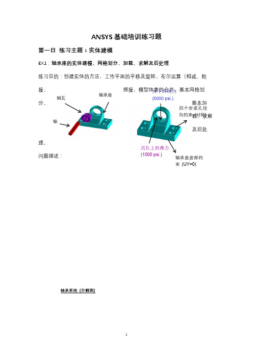
轴承座轴瓦轴 四个安装孔径轴承座底部约沉孔上的推力向下作用力ANSYS 基础培训练习题第一日 练习主题:实体建模EX1:轴承座的实体建模、网格划分、加载、求解及后处理练习目的:创建实体的方法,工作平面的平移及旋转,布尔运算(相减、粘接、搭接,模型体素的合并,基本网格划分。
基本加载、求解及后处理。
问题描述:具体步骤:轴承系统 (分解图)载荷首先进入前处理(/PREP7)1. 创建基座模型生成长方体Main Menu:Preprocessor>Modeling>Create>Volumes>Block>By Dimensions输入x1=0,x2=3,y1=0,y2=1,z1=0,z2=3平移并旋转工作平面Utility Menu>WorkPlane>Offset WP by IncrementsX,Y,Z Offsets 输入2.25,1.25,.75 点击ApplyXY,YZ,ZX Angles输入0,-90点击OK。
创建圆柱体Main Menu:Preprocessor>Modeling>Creat>Cylinder> Solid Cylinder075Radius输入0.75/2, Depth输入-1.5,点击OK。
拷贝生成另一个圆柱体Main Menu:Preprocessor>Modeling>Copy>Volume拾取圆柱体,点击Apply, DZ输入1.5然后点击OK从长方体中减去两个圆柱体Main Menu:Preprocessor>Modeling>Operate>Booleans>Subtract>Volumes首先拾取被减的长方体,点击Apply,然后拾取减去的两个圆柱体,点击OK。
使工作平面与总体笛卡尔坐标系一致Utility Menu>WorkPlane>Align WP with> Global Cartesian2. 创建支撑部分Utility Menu: WorkPlane -> Display Working Plane (toggle on) Main Menu: Preprocessor -> -Modeling-Create -> -Volumes-Block -> By 2 corners & Z 在创建实体块的参数表中输入下列数值:WP X = 0WP Y = 1Width = 1.5Height = 1.75Depth = 0.75OKToolbar: SAVE_DB3. 偏移工作平面到轴瓦支架的前表面Utility Menu: WorkPlane -> Offset WP to -> Keypoints +1. 在刚刚创建的实体块的左上角拾取关键点2. OKToolbar: SAVE_DB4.创建轴瓦支架的上部Main Menu: Preprocessor -> Modeling-Create -> Volumes-Cylinder -> Partial Cylinder + 1). 在创建圆柱的参数表中输入下列参数:WP X = 0WP Y = 0Rad-1 = 0Theta-1 = 0Rad-2 = 1.5Theta-2 = 90Depth = -0.752). OKToolbar: SAVE_DB5. 在轴承孔的位置创建圆柱体为布尔操作生成轴孔做准备Main Menu: Preprocessor -> Modeling-Create -> Volume-Cylinder -> Solid Cylinder + 1.) 输入下列参数:WP X = 0WP Y = 0Radius = 1Depth = -0.18752.) 拾取Apply3.) 输入下列参数:WP X = 0WP Y = 0Radius = 0.85Depth = -24.)拾取OK6.从轴瓦支架“减”去圆柱体形成轴孔.Main Menu: Preprocessor -> Modeling-Operate -> Subtract -> Volumes +1. 拾取构成轴瓦支架的两个体,作为布尔“减”操作的母体。
ansys工程实例(4经典例子)
输气管道受力分析(ANSYS建模)任务和要求:按照输气管道的尺寸及载荷情况,要求在ANSYS中建模,完成整个静力学分析过程。
求出管壁的静力场分布。
要求完成问题分析、求解步骤、程序代码、结果描述和总结五部分。
所给的参数如下:材料参数:弹性模量E=200Gpa; 泊松比0.26;外径R₁=0.6m;内径R₂=0.4m;壁厚t=0.2m。
输气管体内表面的最大冲击载荷P为1Mpa。
四.问题求解(一).问题分析由于管道沿长度方向的尺寸远大于管道的直径,在计算过程中忽略管道的端面效应,认为在其长度方向无应变产生,即可将该问题简化为平面应变问题,选取管道横截面建立几何模型进行求解。
(二).求解步骤定义工作文件名选择Utility Menu→File→Chang Jobname 出现Change Jobname对话框,在[/FILNAM] Enter new jobname 输入栏中输入工作名LEILIN10074723,并将New log and eror file 设置为YES,单击[OK]按钮关闭对话框定义单元类型1)选择Main Meun→Preprocessor→Element Type→Add/Edit/Delte命令,出现Element Type 对话框,单击[Add]按钮,出现Library of Element types对话框。
2)在Library of Element types复选框选择Strctural、Solid、Quad 8node 82,在Element type reference number输入栏中出入1,单击[OK]按钮关闭该对话框。
3. 定义材料性能参数1)单击Main Meun→Preprocessor→Material Props→Material models出现Define Material Behavion 对话框。
选择依次选择Structural、Linear、Elastic、Isotropic选项,出现Linear Isotropic Material Properties For Material Number 1对话框。
ansys工程实例(经典例子)
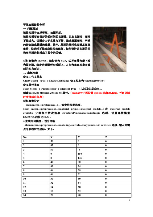
管道支架结构分析一问题描述该结构用于支撑管道,如图所示。
该结构需要有很好的长时间的支撑性,且在支撑时,变形不能过大,否则会由于支撑力不够,造成管道变形,严重的话会造成管道的泄露。
另外,所用的材料也要满足屈服条件,设计时不能造成结构的破坏。
如何设计该支撑的结构和所用的材料成了其中的关键。
材料参数为7E+008,泊松比为0.33,边界条件为最下端为固定端,载荷为管道所在弧面上,方向为垂直且指向弧面的均布面力。
二求解步骤定义工作文件名Utility Menu-->File-->Change Jobname 该工作名为yangxin10054554定义单元类型Main Menu --> Preprocessor--> Element Type --> Add/Edit/Delete…创建mesh200和brick 20node 95单元。
(mesh200还需设置options选择面单元,否则分网时会提示出问题)材料参数设定main menu-->preferences-->…选中结构类选项。
Main menu-->preprocessor-->material props-->material models-->在material models available 分组框中依次选取structural/linear/elastic/isotropic选项,设置弹性模量EX=0.7e9,泊松比=0.33。
4.生成几何模型、划分网格Main menu-->preprocessor-->modeling-->create-->keypoints-->in active cs 选项,输入关键点号和相应的坐标,如下:2)连线Main menu-->preprocessor-->modeling-->create-->lines-->lines-->straightline-->…3) 倒角Main menu-->preprocessor-->modeling-->create-->lines-->line fillet-->...4)对称Main menu-->preprocessor-->modeling-->reflect-->lines-->…之后将所有面add在一起。
ansys有限元建模与分析实例,详细步骤

《有限元法及其应用》课程作业ANSYS应用分析学号:姓名:专业:建筑与土木工程角托架的有限元建模与分析一 、模型介绍本模型是关于一个角托架的简单加载,线性静态结构分析问题,托架的具体形状和尺寸如图所示。
托架左上方的销孔被焊接完全固定,其右下角的销孔受到锥形压力载荷,角托架材料为Q235A 优质钢。
角托架材料参数为:弹性模量366E e psi =;泊松比0.27ν=托架图(厚度:0.5)二、问题分析因为角托架在Z 方向尺寸相对于其在X,Y 方向的尺寸来说很小,并且压力荷载仅作用在X,Y 平面上,因此可以认为这个分析为平面应力状态。
三、模型建立3.1 指定工作文件名和分析标题(1)选择菜单栏Utility Menu →File →Jobname 命令.系统将弹出Jobname(修改文件名)对话框,输入bracket(2)定义分析标题GUI :Utility Menu>Preprocess>Element Type>Add/Edit/Delete 执行命令后,弹出对话框,输入stress in a bracket 作为ANSYS 图形显示时的标题。
3.2设置计算类型Main Menu: Preferences … →select Structural → OK3.3定义单元类型PLANE82 GUI :Main Menu →Preprocessor →Element Type →Add/Edit/Delete 命令,系统将弹出Element Types 对话框。
单击Add 按钮,在对话框左边的下拉列表中单击Structural Solid →Quad 8node 82,选择8节点平面单元PLANE82。
单击ok ,Element Types 对话框,单击Option ,在Element behavior 后面窗口中选取Plane strs w/thk 后单击ok 完成定义单元类型。
(完整版)1车架ANSYS建模过程
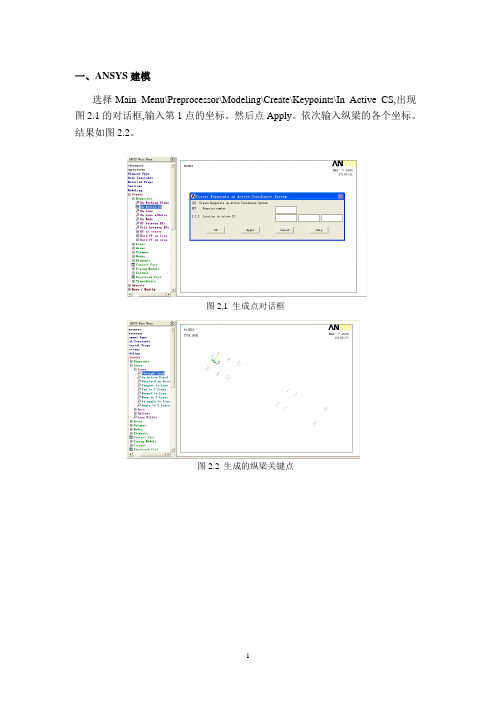
一、ANSYS建模选择Main Menu\Preprocessor\Modeling\Create\Keypoints\In Active CS,出现图2.1的对话框,输入第1点的坐标。
然后点Apply。
依次输入纵梁的各个坐标。
结果如图2.2。
图2.1 生成点对话框图2.2 生成的纵梁关键点图2.3 横梁关键点建立第3,4,5,6横梁在纵梁上的关键点。
选择MainMenu\Preprocessor\Modeling \Create\Keypoints\In Active CS命令。
copy各个横梁的点,以建立横梁翼板。
选择Main Menu\Preprocessor\Modeling\Copy\Keypoints,建立了图2.3中横梁关键点。
图2.4 车架骨架关键点将现所有点向Y轴的负方向偏移100mm,仍然用copy命令。
然后将所有点镜像Main Menu\Preprocessor\Modeling\Reflect\Keypoints,以xz平面为镜象中心。
结果如图2.4。
基本生成了NJ1030车架骨架点模型。
图2.5 车架轮廓将所有的关键点连接生成线(必须依次连接并且都在同一平面内)并如图2.5所示:Main Menu\Preprocessor\Modeling\Create\Lines\Straight Line。
将所有的线连接生成面(必须依次连接并且都在同一平面内),结果如图2.6:Main Menu\Preprocessor\Modeling\Create\Areas\Arbitrary\By Lines。
为了将车架所有的面连接起来以进行网格划分和对梁厚度的不同的设立,需要将所有的面粘合起来。
选择Main Menu\Preprocessor\Modeling\Operate\Booleans\Glue\Areas出现对话框,选择Pick ALL即可。
图2.6 NJ1030车架骨架几何模型至此NJ1030车架的有限元模型以在ANSYS中建立成功。
写给ansys初学者,如何充分运用ansys的HELP

一,写给ansys初学者,如何充分运用ansys的HELP学习ansys,假设说手里只有软件,没有任何的中文图书(其实很多的中文图书就是完全的翻译ansys自带的HELP,而且有些翻译的质量实在是不敢恭维,这里仅说利用ansys自带的HELP).那么我建议以下的这种学习方式,假设你已经有了基本的有限元知识.简易教程中用的是d版ansys9.0sp1.1,养成良好的习惯,每一次的工作都建一个文件夹,并取一个文件名,参看图1.AVI。
或者参看Basic Guide | Chapter 1. Getting Started with ANSYS | 1.2. Building a Model2,首先完成help里面的tutorials,里面有结构学的,电磁学的,热学的,还有流体学的等近十类指南,选择其中的一种或者是两种来做,比如说你是做结构学的,当然就选择结构学的啦,一步步按着指导做下去,以此来熟悉anays的图形操作(GUI).参看图2.AVI学ansys还是要熟悉GUI操作的,每运行一次GUI操作会在ansys的工作目录里面生成一个.LOG文件,适当处理就会得到一个命令流文件,然后可以导入该命令流,就相当于重复了上面的GUI操作(再加入适当的APDL控制语句,就可以以小做大,这是后话,这里先不提),参看图3.avi。
3,看Basic Analysis Guide,建模,加负载,计算,通用后处理,时间后处理的基本用法这里都有了。
图4.avi4,熟悉了基本的操作之后,以后就要看一点命令流了,毕竟命令流效率高,速度快,而且最主要的,ansys高手都在用.Verification Manual,里面给出了264个例子,这是我们的好帮手,一定要熟悉,当然还是要选择自己熟悉的来做。
比如说我是做动力学分析的,就选择一个动力的例子来做。
如图5.avi.这些我觉得是非常非常有用的。
在这里你要熟悉里面的命令是什么意思,就得一条条查查了,好在里面的许多命令都是英文的缩写,大多可以猜出是什么意思来,但许多还是要自己查的。
ansys案例
ansys案例Ansys案例。
在工程领域,Ansys是一个非常重要的工具,它可以用来进行有限元分析,对结构、流体、热传导等进行模拟,帮助工程师们更好地设计和优化产品。
下面我们将介绍一个Ansys案例,来看看它是如何应用于实际工程问题中的。
我们选取了一个汽车发动机的热传导分析作为案例。
汽车发动机在工作时会产生大量的热量,如果散热不好,就会导致发动机过热,甚至损坏。
因此,对发动机的热传导特性进行分析非常重要。
首先,我们需要建立发动机的三维模型,并对其进行网格划分。
Ansys提供了强大的建模和网格划分工具,可以快速准确地完成这一步骤。
接下来,我们需要定义材料的热传导性质,包括导热系数、比热容等参数。
这些参数对于模拟结果的准确性至关重要。
然后,我们需要设置边界条件和加载条件。
在这个案例中,发动机的外表面会受到空气的冷却,因此我们需要定义外表面的对流换热系数。
同时,发动机内部会有燃烧产生的热量,需要通过内部表面来定义热源。
这些边界条件和加载条件的设置也是Ansys的一大特色,用户可以根据实际情况进行灵活定义。
完成了前期的准备工作后,我们就可以进行热传导分析了。
Ansys会对整个发动机进行数值求解,得到温度场的分布情况。
通过分析温度场,我们可以看出发动机的哪些部位温度较高,哪些部位温度较低,从而找出散热不良的部位。
通过这个案例,我们可以看到Ansys在工程领域的强大应用价值。
它不仅可以帮助工程师们进行复杂的物理场模拟,还可以为工程设计和优化提供重要参考。
当然,Ansys的应用远不止于此,它还可以用于流体动力学分析、结构强度分析等多个领域。
总的来说,Ansys案例的介绍可以帮助我们更好地了解该软件在工程领域的应用,对于工程师们来说,掌握Ansys是非常重要的,它可以帮助他们更好地解决工程问题,提高工作效率,降低成本,提高产品质量。
希望这个案例可以为大家带来一些启发,也希望Ansys在未来能够发挥更大的作用,为工程领域的发展贡献力量。
Ansys 结构 元案例分析 轴承支座
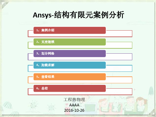
4、加载求解
7、开始求解:
4、加载求解
1、打开单元形状显示开关:
5、查看结果
1、打开单元形状显示开关:
5、查看结果
2、查看变形:
5、查看结果
5、查看结果
5、查看结果
查看应力
节点应力云图
Plot Result X方向节点应力云图
Y方向节点应力云图
Z方向节点应力云图
5、查看结果
查看位移
节点位移云图
• 施加约束; • 施加载荷; • 设置输出控制项;
4、加载求解
1、在底部施加约束,固定支座:
4、加载求解
2、在螺栓孔施加约束,固定孔:
4、加载求解
3、在对应面上定义轴向载荷,2x104psi :
4、加载求解
4、在轴承孔上定义轴向载荷,105psi :
5、设置用箭头来显示力:
4、加载求解
6、设置输出控制项:
2
2、定义材料属性
3、划分网格
2、定义材料属性
3、划分网格
2、定义材料属性
3、划分网格
3、设置尺寸单元
3、划分网格开始划分ຫໍສະໝຸດ 3、划分网格开始划分
3、划分网格
划分完成
3、划分网格
共划分282868个单元,其中有10个单元形状不好,但在允许范围内,不影响后续分析;
3、划分网格
4、加载求解
2、支座建模
体删除:Preprocessor-Modeling-Delete-Volumes and Below
2、支座建模
通过关键点建面:Preprocessor-Modeling-Create-Areas-Arbitrary-Through KPs
2、支座建模
- 1、下载文档前请自行甄别文档内容的完整性,平台不提供额外的编辑、内容补充、找答案等附加服务。
- 2、"仅部分预览"的文档,不可在线预览部分如存在完整性等问题,可反馈申请退款(可完整预览的文档不适用该条件!)。
- 3、如文档侵犯您的权益,请联系客服反馈,我们会尽快为您处理(人工客服工作时间:9:00-18:30)。
Introductory Tutorials Page: 12.1. Static Analysis of a Corner Bracket 2.1.1. Problem SpecificationApplicable ANSYS Products: Level of Difficulty: Interactive Time Required: Discipline: Analysis Type: Element Types Used: ANSYS Features Demonstrated: Applicable Help Available: ANSYS Multiphysics, ANSYS Mechanical, ANSYS Structural, ANSYS ED easy 60 to 90 minutes structural linear static PLANE183 solid modeling including primitives, Boolean operations, and fillets; tapered pressure load; deformed shape and stress displays; listing of reaction forces; examination of structural energy error Structural Static Analysis in the Structural Analysis Guide, PLANE183 in the Element Reference.2.1.2. Problem DescriptionThis is a simple, single load step, structural static analysis of the corner angle bracket shown below. The upper left-hand pin hole is constrained (welded) around its entire circumference, and a tapered pressure load is applied to the bottom of the lower righthand pin hole. The objective of the problem is to demonstrate the typical ANSYS analysis procedure. The US Customary system of units is used.2.1.2.1. GivenThe dimensions of the corner bracket are shown in the accompanying figure. The bracket is made of A36 steel with a Young’s modulus of 30E6 psi and Poisson’s ratio of .27.2.1.2.2. Approach and AssumptionsAssume plane stress for this analysis. Since the bracket is thin in the z direction (1/2 inch thickness) compared to its x and y dimensions, and since the pressure load acts only in the x-y plane, this is a valid assumption. Your approach is to use solid modeling to generate the 2-D model and automatically mesh it with nodes and elements. (Another alternative in ANSYS is to create the nodes and elements directly.)2.1.2.3. Summary of StepsContains proprietary and confidential information of ANSYS, Inc. and its subsidiaries and affiliates利用 pdfFactory Pro 测试版本创建的PDF文档 Introductory Tutorials Page: 2Use the information in the problem description and the steps below as a guideline in solving the problem on your own. Or, use the detailed interactive step-by-step solution by choosing the link for step 1.Note: If your system includes a Flash player (from Macromedia, Inc.), you can view demonstration videos of eachstep by pointing your web browser to the following URL address: http://www.ansys. com/techmedia/structural_tutorial_videos.html .Build Geometry1. Define rectangles. 2. Change plot controls and replot. 3. Change working plane to polar and create first circle. 4. Move working plane and create second circle. 5. Add areas. 6. Create line fillet. 7. Create fillet area. 8. Add areas together. 9. Create first pin hole. 10. Move working plane and create second pin hole. 11. Subtract pin holes from bracket. 12. Save the database as model.db.Define Materials13. Set Preferences. 14. Define Material Properties. 15. Define element types and options. 16. Define real constants.Generate Mesh17. Mesh the area. 18. Save the database as mesh.db.Apply Loads19. Apply displacement constraints. 20. Apply pressure load.Obtain SolutionContains proprietary and confidential information of ANSYS, Inc. and its subsidiaries and affiliates利用 pdfFactory Pro 测试版本创建的PDF文档 Introductory Tutorials Page: 321. Solve.Review Results22. Enter the general postprocessor and read in the results. 23. Plot the deformed shape. 24. Plot the von Mises equivalent stress. 25. List the reaction solution. 26. Exit the ANSYS program.2.1.3. Build GeometryThis is the beginning of Preprocessing.2.1.3.1. Step 1: Define rectangles.There are several ways to create the model geometry within ANSYS, some more convenient than others. The first step is to recognize that you can construct the bracket easily with combinations of rectangles and circle Primitives. Decide where the origin will be located and then define the rectangle and circle primitives relative to that origin. The location of the origin is arbitrary. Here, use the center of the upper left-hand hole. ANSYS does not need to know where the origin is. Simply begin by defining a rectangle relative to that location. In ANSYS, this origin is called the global origin. 1. Main Menu> Preprocessor> Modeling> Create> Areas> Rectangle> By Dimensions 2. Enter the following: X1 = 0 (Note: Press the Tab key between entries) X2 = 6 Y1 = -1 Y2 = 1 3. Apply to create the first rectangle. 4. Enter the following: X1 = 4 X2 = 6 Y1 = -1 Y2 = -3 5. OK to create the second rectangle and close the dialog box.Contains proprietary and confidential information of ANSYS, Inc. and its subsidiaries and affiliates利用 pdfFactory Pro 测试版本创建的PDF文档 Introductory Tutorials Page: 42.1.3.2. Step 2: Change plot controls and replot.The area plot shows both rectangles, which are areas, in the same color. To more clearly distinguish between areas, turn on area numbers and colors. The "Plot Numbering Controls" dialog box on the Utility Menu controls how items are displayed in the Graphics Window. By default, a "replot" is automatically performed upon execution of the dialog box. The replot operation will repeat the last plotting operation that occurred (in this case, an area plot). 1. Utility Menu> Plot Ctrls> Numbering 2. Turn on area numbers. 3. OK to change controls, close the dialog box, and replot.Before going to the next step, save the work you have done so far. ANSYS stores any input data in memory to the ANSYS database. To save that database to a file, use the SAVE operation, available as a tool on the Toolbar. ANSYS names the database file using the format jobname.db . If you started ANSYS using the product launcher, you can specify a jobname at that point (the default jobname is file). You can check the current jobname at any time by choosing Utility Menu> List> Status> Global Status. You can also save the database at specific milestone points in the analysis (such as after the model is complete, or after the model is meshed) by choosing Utility Menu> File> Save As and specifying different jobnames (model.db, or mesh.db, etc.). It is important to do an occasional save so that if you make a mistake, you can restore the model from the last saved state. You restore the model using the RESUME operation, also available on the Toolbar. (You can also find SAVE and RESUME on the Utility Menu, under File.) 4. Toolbar: SAVE_DB.2.1.3.3. Step 3: Change working plane to polar and create first circle.The next step in the model construction is to create the half circle at each end of the bracket. You will actually create a full circle on each end and then combine the circles and rectangles with a Boolean "add" operation (discussed in step 5.). To create the circles, you will use and display the working plane. You could have shown the working plane as you created the rectangles but it was not necessary.Contains proprietary and confidential information of ANSYS, Inc. and its subsidiaries and affiliates利用 pdfFactory Pro 测试版本创建的PDF文档 Introductory Tutorials Page: 5Before you begin however, first "zoom out" within the Graphics Window so you can see more of the circles as you create them. You do this using the "Pan-Zoom-Rotate" dialog box, a convenient graphics control box you’ll use often in any ANSYS session.1. 2. 3. 4.Utility Menu> PlotCtrls> Pan, Zoom, Rotate Click on small dot once to zoom out. Close dialog box. Utility Menu> WorkPlane> Display Working Plane (toggle on)5. 6. 7. 8. 9.Notice the working plane origin is immediately plotted in the Graphics Window. It is indicated by the WX and WY symbols; right now coincident with the global origin X and Y symbols. Next you will change the WP type to polar, change the snap increment, and display the grid. Utility Menu> WorkPlane> WP Settings Click on Polar. Click on Grid and Triad. Enter .1 for snap increment. OK to define settings and close the dialog box.10. Main Menu> Preprocessor> Modeling> Create> Areas> Circle> Solid Circle Be sure to read prompt before picking. 11. Pick center point at: WP X = 0 (in Graphics Window shown below) WP Y = 0 12. Move mouse to radius of 1 and click left button to create circle.Contains proprietary and confidential information of ANSYS, Inc. and its subsidiaries and affiliates利用 pdfFactory Pro 测试版本创建的PDF文档 Introductory Tutorials Page: 613. OK to close picking menu. 14. Toolbar: SAVE_DB.Note: While you are positioning the cursor for picking, the "dynamic" WP X and Y values are displayed in the SolidCircular Area dialog box. Also, as an alternative to picking, you can type these values along with the radius into the dialog box.2.1.3.4. Step 4: Move working plane and create second circle.To create the circle at the other end of the bracket in the same manner, you need to first move the working plane to the origin of the circle. The simplest way to do this without entering number offsets is to move the WP to an average keypoint location by picking the keypoints at the bottom corners of the lower, right rectangle. 1. Utility Menu> WorkPlane> Offset WP to> Keypoints 2. Pick keypoint at lower left corner of rectangle. 3. Pick keypoint at lower right of rectangle.4. OK to close picking menu.5. Main Menu> Preprocessor> Modeling> Create> Areas> Circle> Solid Circle 6. Pick center point at: WP X = 0 WP Y = 0 7. Move mouse to radius of 1 and click left button to create circle.Contains proprietary and confidential information of ANSYS, Inc. and its subsidiaries and affiliates利用 pdfFactory Pro 测试版本创建的PDF文档 Introductory Tutorials Page: 78. OK to close picking menu.9. Toolbar: SAVE_DB.2.1.3.5. Step 5: Add areas.Now that the appropriate pieces of the model are defined (rectangles and circles), you need to add them together so the model becomes one continuous piece. You do this with the Boolean add operation for areas.1. Main Menu> Preprocessor> Modeling> Operate> Booleans> Add> Areas 2. Pick All for all areas to be added.3. Toolbar: SAVE_DB.2.1.3.6. Step 6: Create line fillet.1. Utility Menu> PlotCtrls> Numbering 2. Turn on line numbering. 3. OK to change controls, close the dialog box, and automatically replot.4. Utility Menu> WorkPlane> Display Working Plane (toggle off)Contains proprietary and confidential information of ANSYS, Inc. and its subsidiaries and affiliates利用 pdfFactory Pro 测试版本创建的PDF文档 Introductory Tutorials Page: 8Working Plane (toggle off)5. Main Menu> Preprocessor> Modeling> Create> Lines> Line Fillet 6. Pick lines 17 and 8.7. OK to finish picking lines (in picking menu). 8. Enter .4 as the radius. 9. OK to create line fillet and close the dialog box. 10. Utility Menu> Plot> Lines2.1.3.7. Step 7: Create fillet area.1. Utility Menu> PlotCtrls> Pan, Zoom, Rotate 2. Click on Zoom button. 3. Move mouse to fillet region, click left button, move mouse out and click again.4. Main Menu> Preprocessor> Modeling> Create> Areas> Arbitrary> By LinesContains proprietary and confidential information of ANSYS, Inc. and its subsidiaries and affiliates利用 pdfFactory Pro 测试版本创建的PDF文档 Introductory Tutorials Page: 95. Pick lines 4, 5, and 1.6. 7. 8. 9.OK to create area and close the picking menu. Click on Fit button. Close the Pan, Zoom, Rotate dialog box. Utility Menu> Plot> Areas10. Toolbar: SAVE_DB.2.1.3.8. Step 8: Add areas together.1. Main Menu> Preprocessor> Modeling> Operate> Booleans> Add> Areas 2. Pick All for all areas to be added.3. Toolbar: SAVE_DB.2.1.3.9. Step 9: Create first pin hole.Contains proprietary and confidential information of ANSYS, Inc. and its subsidiaries and affiliates利用 pdfFactory Pro 测试版本创建的PDF文档 Introductory Tutorials Page: 101. Utility Menu> WorkPlane> Display Working Plane (toggle on)2. Main Menu> Preprocessor> Modeling> Create> Areas> Circle> Solid Circle 3. Pick center point at: WP X = 0 (in Graphics Window) WP Y = 0 4. Move mouse to radius of .4 (shown in the picking menu) and click left button to create circle. 5. OK to close picking menu.2.1.3.10. Step 10: Move working plane and create second pin hole.1. Utility Menu> WorkPlane> Offset WP to> Global Origin 2. Main Menu> Preprocessor> Modeling> Create> Areas> Circle> Solid Circle 3. Pick center point at: WP X = 0 (in Graphics Window) WP Y = 0 4. 5. 6. 7. Move mouse to radius of .4 (shown in the picking menu) and click left mouse button to create circle. OK to close picking menu. Utility Menu> WorkPlane> Display Working Plane (toggle off) Utility Menu> Plot> ReplotFrom this area plot, it appears that one of the pin hole areas is not there. However, it is there (as indicated by the presence of its lines), you just can't see it in the final display of the screen. That is because the bracket area is drawn on top of it. An easy way to see all areas is to plot the lines instead. 8. Utility Menu> Plot> Lines9. Toolbar: SAVE_DB.2.1.3.11. Step 11: Subtract pin holes from bracket.1. 2. 3. 4. Main Menu> Preprocessor> Modeling> Operate> Booleans> Subtract> Areas Pick bracket as base area from which to subtract. Apply (in picking menu). Pick both pin holes as areas to be subtracted.Contains proprietary and confidential information of ANSYS, Inc. and its subsidiaries and affiliates利用 pdfFactory Pro 测试版本创建的PDF文档 OK to subtract holes and close picking menu.go back and remesh, you'll need to resume this database file. You will save it as model.db.for the database file name.using.’Linear, Elastic, Isotropic.Enter .27 for PRXY.Material> Exit(You will define the thickness as a real constant in the next step.)Add an element type.).are to be defined.dialog box.Add a real constant set.help information, click on the Back button.the dialog box.Set Global Size control.OK.Click on Mesh.mesh.db.for database file name.10, 9, 11, 12).OK (in picking menu).Click on All DOF.OK to apply constraints and close dialog box.1.Main Menu> Solution> Define Loads> Apply>Structural> Pressure> On Lines2.Pick line defining bottom left part of the circle (line 6).3.Apply.5.Enter 500 for optional value.7.Pick line defining bottom right part of circle (line 7).8.Apply.10.Enter 50 for optional value.12.Toolbar: SAVE_DB.2.1.7. Obtain Solution2.1.7.1. Step 21: Solve.1.Main Menu> Solution> Solve>Current LS2.Review the information in the statuswindow, then choose File> Close(Windows), or Close (X11/Motif), toclose the window.Choose Yes to any Verify messages that appear.4.Close the information window whensolution is done.Choose Def + undeformed.You can also produce an animated version Choose Def + undeformed.Make choices in the Animation ControllerChoose Stress item to be contoured. OK.Choose Stress item to be contoured.OK.Scroll down and find the total vertical force, FY.Choose Quit - No Save!。