NTN机床用精密滚动轴承样本
轴承样本
轴承:轴承是当代机械设备中一种重要零部件。
它的主要功能是支撑机械旋转体,降低其运动过程中的摩擦系数,并保证其回转精度。
结构分类:滑动轴承滑动轴承不分内外圈也没有滚动体,一般是由耐磨材料制成。
常用于低速,轻载及加注润滑油及维护困难的机械转动部位。
关节轴承关节轴承的滑动接触表面为球面,主要适用于摆动运动、倾斜运动和旋转运动。
滚动轴承滚动轴承按其所能承受的载荷方向或公称接触角的不同分为向心轴承和推力轴承。
其中径向接触轴承为公称接触角为0的向心轴承,向心角接触轴承为公称接触角大于0到45的向心轴承。
轴向接触轴承为公称接触角为90的推力轴承,推力角接触轴承为公称接触角大于45但小于90的推力轴承。
按滚动体的形状可分为球轴承和滚子轴承。
滚子轴承按滚子种类分为:圆柱滚子轴承、滚针轴承、圆锥滚子轴承和调心滚子轴承。
按其工作时能否调心分为调心轴承----滚道是球面形的,能适应两滚道轴心线间的角偏差及角运动的轴承和非调心轴承(刚性轴承)----能阻抗滚道间轴心线角偏移的轴承。
按滚动体的列数分为单列轴承、双列轴承和多列轴承。
按其部件(套圈)能否分离分为可分离轴承和不可分离轴承。
按其结构形状(如有无装填槽,有无内、外圈以及套圈的形状,挡边的结构,甚至有无保持架等)还可以分为多种结构类型。
按其外径尺寸大小分为微型轴承(<26mm)、小型轴承(28-55mm)、中小型轴承(60-115)、中大型轴承(120-190mm)、大型轴承(200-430mm)和特大型轴承(>440mm)。
按应用领域分为电机轴承、轧机轴承、主轴承等。
按材料分为陶瓷轴承、塑料轴承等。
深沟球轴承深沟球轴承是最具代表性的滚动轴承。
与尺寸相同的其它类型轴承相比,该类轴承摩擦系数小,极限转速高,结构简单,制造成本低,精度高,无需经常维护,而且尺寸范围大、形式多,是应用最广的一类轴承。
它主要承受径向载荷,也可承受一定的轴向载荷。
当其仅承受径向载荷时,接触角为零。
INA FAG轴承样本中文版-承受联合载荷的高精密轴承
d3
HM
C H1 H
H2
d D1
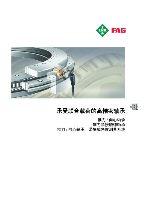
推力 / 向心轴承 推力角接触球轴承
产品概览 特性
设计与安全指南
精度 刚度 特殊设计 尺寸表
页 推力 / 向心轴承,推力角接触球轴承.................................... 1112
应用领域 .............................................................................. 1114 推力 / 向心轴承 .................................................................... 1115 推力角接触球轴承................................................................ 1115 工作温度 .............................................................................. 1115 后缀 ..................................................................................... 1115
推力 角接触球轴承
............................................................................................................. 1110
推力角接触球轴承 ZKLDF 是低摩擦、即装即用、预填润滑脂的 具有很高精度的单元,可用于高速,高轴向和径向载荷以及倾覆 刚度要求高的场合。 推力角接触轴承尤其适用于承受联合载荷的精密应用。它们适用 于回转工作台、铣削、磨削、珩磨头以及测量、测试设备。
FAG、SKF、NSK、NTN、KOYO轴承后缀含义

FAG轴承代号由基本代号、前置代号和后置代号构成:基本代号表示轴承的基本类型、结构和尺寸;前置代号表示轴承零件置于基本代号之前;后置代号表示轴承结构形状、尺寸、密封、保持架、公差、游隙、热处理、包装、技术要求等有改变时,在轴承基本代号后添加的补充代号。
前置代号前置代号R 直接放在轴承基本代号之前,其余代号用小圆点与基本代号隔开。
GS.-- 推力圆柱滚子轴承座圈。
例:GS.81112K.-- 滚动体与保持架的组合件。
例:推力圆柱滚子与保持架的组合件K.81108R-- 不带可分离内圈或外圈的轴承。
例:RNU207-- 不带内圈的NU207 轴承WS-- 推力圆柱滚子轴承轴圈。
例:WS.81112后置代号-- 内部设计-- 外形尺寸及变形设计-- 密封-- 保持架-- 公差-- 游隙-- 热处理-- 特殊设计-- 机床主轴轴承-- 低噪省轴承后置代号置于基本代号的后面。
当具有多组后置代号时,应按轴承代号表中所列后置代号的顺序从左至右排列。
某些后置代号前用小圆点与基本代号隔开。
后置代号—内部结构A 、B 、C 、D 、E-- 内部结构变化例: 角接触球轴承7205C 、7205E 、7205B ,C—15 °接触角、E—25 °触角、B—40 °接触角例:圆柱滚子、调心滚子及推力调心滚子轴承N309E 、21309 E 、29412E--加强型设计,轴承负载能力提高。
VH-- 滚子自锁的满滚子圆柱滚子轴承(滚子的复圆直径不同于同型号的标准轴承)。
例:NJ2312VH后置代号—轴承外形尺寸及外部结构DA--带双半内圈的可分离型双列角接触球轴承。
例:3306DADZ--圆柱型外径的滚轮轴承。
例:ST017DZK--圆锥孔轴承,锥度1 :12 。
例:2308K 。
K30--圆锥孔轴承,锥度1 :30 。
例:24040 K30 。
2LS--双内圈两面带防尘盖的双列圆柱滚子轴承。
例:NNF5026VC.2LS.V--内部结构变化,双内圈,两面带防尘盖、满滚子双列圆柱滚子轴承。
NSK轴承样本

Higher Load Rating
Basic dynamic load rating, N Basic dynamic load rating, N
600 000
EM M 500 000
400 000
300 000
200 000
100 000
0
210
220
310
320
Bearing number
1 200 000
8 500
10 000
90
23
1.5
1.5
52
83 000
81 500
6 700
8 500
85
19
1.1
1.1
54.5
63 000
66 500
7 500
9 000
100
25
1.5
1.5
58.5
97 500
98 500
6 300
7 500
90
20
1.1
1.1
59.5
69 000
76 500
7 100
8 500
NU313EM NJ NUP
76
NU214EM NJ NUP
78
NU314EM NJ NUP
81
NU215EM NJ NUP
83
NU315EM NJ NUP
Tests confirm that the stress levels of NSK’s EM series cages are 50% lower than that of major competitor’s M series.
Cage strength test results
JB/T11251—2011《滚动轴承冲压外围滚针离合器》标准介绍
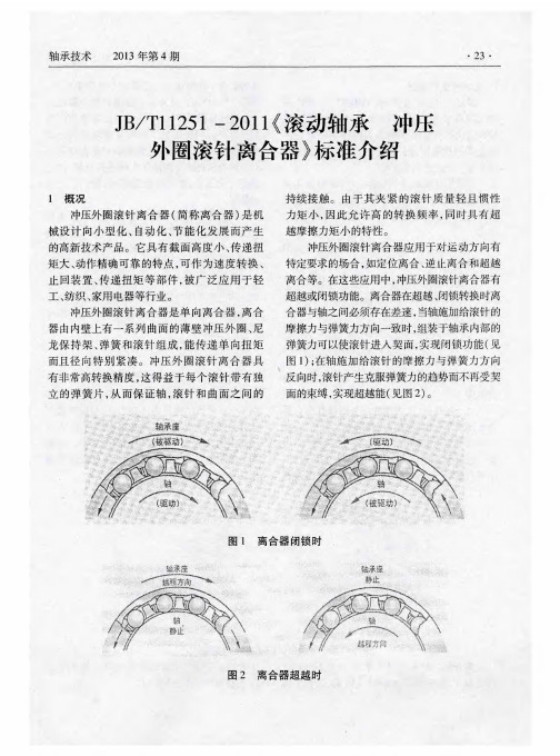
表 l
项 目 计算内容
. 计算公式
说明
1 当量 曲率 半径 P = R×r/(R+r)
R:离合 器滚 针 总体 公称 内径 ,mm; r:滚针 半 径 ,mm
O.418(N×E /l XP ) ≤ E :当量弹性模量 ,(2.1 X 10 );
=
2 接触应力 [ 。 ]
示 ,对于尺寸非标 的离 合器,其尺寸代号则为
a)离合器所使用的冲压外圈,与冲压外圈
“离合器滚针总体公称 内径毫米数 ×离合器公 滚针轴承所使用的外圈一样 ,采用深冲用冷轧
称外径毫米数 ×离合器公称宽度毫米数”;
低碳 钢 板 (带 );
e)后置代 号 用 “一KF”、“一R”、“一KFR”
他工程塑料材料 ;
3.3 外 形尺寸
c)钢制弹簧 (片 )一般采用 的不锈钢冷轧
美 国 TIMKEN—TORRINGTON公 司和 日本 钢带 ;离合器弹簧(片)与保持架一体 ,也采用
NSK公司生产 的冲压外 圈滚针离合器其外形 工 程塑 料 PA66- GF25。
尺寸既有公制系列 ,也有英 制系列 ;德 国 INA 3.5 力 矩
z:滚针长度 ,mm; [ ]
:许 用接 触应力 31000—33000,N
3 正压力 N
= M 。/R × X
:摩 擦 系数 (0.1); :滚针 数
4 计算力矩 M
ti=p×M t
:传递的额定力矩 ,N·m; :工 作贮 备 系数 (1.4—5)
注:传递 的额定力矩 =( /0.418) ×Z×R × × X r/[E × X(R+r)],在此力矩作用
a)删
NTN 轴承(轴承座)样本
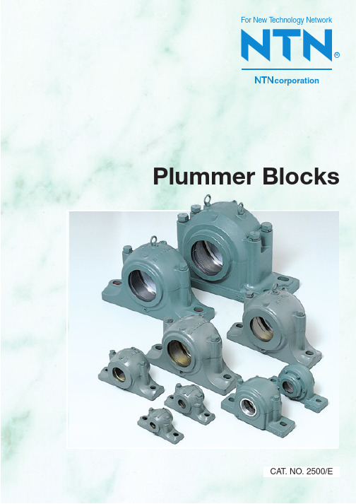
Plummer BlocksFor New T echnology NetworkRcorporationCAT. NO. 2500/EWarrantyNTN warrants, to the original purchaser only, that the delivered product which is the subject of this sale (a) will conform to drawings and specifications mutually established in writing as applicable to the contract, and (b) be free from defects in material or fabrication. The duration of this warranty is one year from date of delivery. If the buyer discovers within this period a failure of the product to conform to drawings or specifications, or a defect in material or fabrication, it must promptly notify NTN in writing. In no event shall such notification be received by NTN later than 13 months from the date of delivery. Within a reasonable time after such notification, NTN will, at its option, (a) correct any failure of the product to conform to drawings, specifications or any defect in material or workmanship, with either replacement or repair of the product, or (b) refund, in part or in whole, the purchase price. Such replacement and repair, excluding charges for labor, is at NTN's expense. All warranty service will be performed at service centers designated by NTN. These remedies are the purchaser's exclusive remedies for breach of warranty.NTN does not warrant (a) any product, components or parts not manufactured by NTN, (b) defects caused by failure to provide a suitable installation environment for the product, (c) damage caused by use of the product for purposes other than those for which it was designed, (d) damage caused by disasters such as fire, flood, wind, and lightning, (e) damage caused by unauthorized attachments or modification, (f) damage during shipment, or (g) any other abuse or misuse by the purchaser.THE FOREGOING WARRANTIES ARE IN LIEU OF ALL OTHER WARRANTIES, EXPRESS OR IMPLIED, INCLUDING BUT NOT LIMITED TO THE IMPLIED WARRANTIES OF MERCHANTABILITY AND FITNESS FOR A PARTICULAR PURPOSE.In no case shall NTN be liable for any special, incidental, or consequential damages based upon breach of warranty, breach of contract, negligence, strict tort, or any other legal theory,and in no case shall total liability of NTN exceed the purchase price of the part upon which such liability is based. Such damages include, but are not limited to, loss of profits, loss of savings or revenue, loss of use of the product or any associated equipment, cost of capital, cost of any substitute equipment, facilities or services, downtime, the claims of third parties including customers, and injury to property. Some states do not allow limits on warranties, or on remedies for breach in certain transactions. In such states, the limits in this paragraph and in paragraph (2) shall apply to the extent allowable under case law and statutes in such states.Any action for breach of warranty or any other legal theory must be commenced within 15 months following delivery of the goods.Unless modified in a writing signed by both parties, this agreement is understood to be the complete and exclusive agreement between the parties, superceding all prior agreements, oral or written, and all other communications between the parties relating to the subject matter of this agreement. No employee of NTN or any other party is authorized to make any warranty in addition to those made in this agreement.This agreement allocates the risks of product failure between NTN and the purchaser. This allocation is recognized by both parties and is reflected in the price of the goods. The purchaser acknowledges that it has read this agreement, understands it, and is bound by its terms.©NTN Corporation. 1998Although care has been taken to assure the accuracy of the data compiled in this catalog, NTN does not assume any liability to any company or person for errors or omissions.Unit type52 59Split type34 51Technical Data 3 32Specialized Plummer Blocks 60 63CONTENTSNTN PLUMMER BLOCKSCONTENTS1. Structure⋯⋯⋯⋯⋯⋯⋯⋯⋯⋯⋯⋯⋯⋯⋯⋯⋯⋯⋯⋯⋯⋯⋯⋯⋯⋯⋯⋯⋯⋯⋯⋯⋯⋯32. Plummer Block and Rolling Bearing Tolerances⋯⋯⋯⋯⋯⋯⋯⋯⋯⋯⋯⋯⋯⋯⋯⋯42.1 Plummer block tolerances⋯⋯⋯⋯⋯⋯⋯⋯⋯⋯⋯⋯⋯⋯⋯⋯⋯⋯⋯⋯⋯⋯⋯⋯⋯42.2 Machining tolerances of mounting bolt seat faces⋯⋯⋯⋯⋯⋯⋯⋯⋯⋯⋯⋯⋯⋯⋯82.3 Rolling bearing accuracies⋯⋯⋯⋯⋯⋯⋯⋯⋯⋯⋯⋯⋯⋯⋯⋯⋯⋯⋯⋯⋯⋯⋯⋯⋯92.4 Rolling bearing internal clearance⋯⋯⋯⋯⋯⋯⋯⋯⋯⋯⋯⋯⋯⋯⋯⋯⋯⋯⋯⋯⋯113. Plummer Block and Bearing Materials⋯⋯⋯⋯⋯⋯⋯⋯⋯⋯⋯⋯⋯⋯⋯⋯⋯⋯⋯⋯133.1 Plummer block materials⋯⋯⋯⋯⋯⋯⋯⋯⋯⋯⋯⋯⋯⋯⋯⋯⋯⋯⋯⋯⋯⋯⋯⋯⋯133.2 Bearing materials⋯⋯⋯⋯⋯⋯⋯⋯⋯⋯⋯⋯⋯⋯⋯⋯⋯⋯⋯⋯⋯⋯⋯⋯⋯⋯⋯⋯144. Strength of Plummer Blocks, and Combination with Bearings⋯⋯⋯⋯⋯⋯⋯⋯⋯154.1 Strength of plummer blocks⋯⋯⋯⋯⋯⋯⋯⋯⋯⋯⋯⋯⋯⋯⋯⋯⋯⋯⋯⋯⋯⋯⋯⋯154.2 Combinations of plummer blocks and bearings⋯⋯⋯⋯⋯⋯⋯⋯⋯⋯⋯⋯⋯⋯⋯165. Allowable Speed⋯⋯⋯⋯⋯⋯⋯⋯⋯⋯⋯⋯⋯⋯⋯⋯⋯⋯⋯⋯⋯⋯⋯⋯⋯⋯⋯⋯⋯⋯186. Bearing Seals⋯⋯⋯⋯⋯⋯⋯⋯⋯⋯⋯⋯⋯⋯⋯⋯⋯⋯⋯⋯⋯⋯⋯⋯⋯⋯⋯⋯⋯⋯⋯196.1 Contact seals⋯⋯⋯⋯⋯⋯⋯⋯⋯⋯⋯⋯⋯⋯⋯⋯⋯⋯⋯⋯⋯⋯⋯⋯⋯⋯⋯⋯⋯⋯196.2 Non-contact seals⋯⋯⋯⋯⋯⋯⋯⋯⋯⋯⋯⋯⋯⋯⋯⋯⋯⋯⋯⋯⋯⋯⋯⋯⋯⋯⋯⋯206.3 Combination seals⋯⋯⋯⋯⋯⋯⋯⋯⋯⋯⋯⋯⋯⋯⋯⋯⋯⋯⋯⋯⋯⋯⋯⋯⋯⋯⋯⋯207. Shaft Design⋯⋯⋯⋯⋯⋯⋯⋯⋯⋯⋯⋯⋯⋯⋯⋯⋯⋯⋯⋯⋯⋯⋯⋯⋯⋯⋯⋯⋯⋯⋯217.1 Bearing-to-shaft fit⋯⋯⋯⋯⋯⋯⋯⋯⋯⋯⋯⋯⋯⋯⋯⋯⋯⋯⋯⋯⋯⋯⋯⋯⋯⋯⋯⋯217.2 Mounting dimensions⋯⋯⋯⋯⋯⋯⋯⋯⋯⋯⋯⋯⋯⋯⋯⋯⋯⋯⋯⋯⋯⋯⋯⋯⋯⋯218. Lubrication⋯⋯⋯⋯⋯⋯⋯⋯⋯⋯⋯⋯⋯⋯⋯⋯⋯⋯⋯⋯⋯⋯⋯⋯⋯⋯⋯⋯⋯⋯⋯⋯238.1 Grease lubrication⋯⋯⋯⋯⋯⋯⋯⋯⋯⋯⋯⋯⋯⋯⋯⋯⋯⋯⋯⋯⋯⋯⋯⋯⋯⋯⋯⋯239. Handling the Plummer Blocks and Bearings⋯⋯⋯⋯⋯⋯⋯⋯⋯⋯⋯⋯⋯⋯⋯⋯⋯249.1 Inspection before installation⋯⋯⋯⋯⋯⋯⋯⋯⋯⋯⋯⋯⋯⋯⋯⋯⋯⋯⋯⋯⋯⋯⋯249.2 Preparation for installing the bearing⋯⋯⋯⋯⋯⋯⋯⋯⋯⋯⋯⋯⋯⋯⋯⋯⋯⋯⋯⋯249.3 Installation of the bearing and associated components⋯⋯⋯⋯⋯⋯⋯⋯⋯⋯⋯⋯259.4 Assembling the plummer blocks⋯⋯⋯⋯⋯⋯⋯⋯⋯⋯⋯⋯⋯⋯⋯⋯⋯⋯⋯⋯⋯⋯299.5 Running inspection⋯⋯⋯⋯⋯⋯⋯⋯⋯⋯⋯⋯⋯⋯⋯⋯⋯⋯⋯⋯⋯⋯⋯⋯⋯⋯⋯309.6 Maintenance and inspection⋯⋯⋯⋯⋯⋯⋯⋯⋯⋯⋯⋯⋯⋯⋯⋯⋯⋯⋯⋯⋯⋯⋯319.7 Bearing disassembly⋯⋯⋯⋯⋯⋯⋯⋯⋯⋯⋯⋯⋯⋯⋯⋯⋯⋯⋯⋯⋯⋯⋯⋯⋯⋯⋯319.8 Cleaning the bearing⋯⋯⋯⋯⋯⋯⋯⋯⋯⋯⋯⋯⋯⋯⋯⋯⋯⋯⋯⋯⋯⋯⋯⋯⋯⋯329.9 Storing the bearing⋯⋯⋯⋯⋯⋯⋯⋯⋯⋯⋯⋯⋯⋯⋯⋯⋯⋯⋯⋯⋯⋯⋯⋯⋯⋯⋯32Plummer Blocks1. Structureloosening due to vibration and impact.For draining old lubricant.SealExcellent sealing performance.Self-aligning rolling bearingSelf-aligning ball or roller bearing is built into plummer block.Simplifies installation Products painted in user-specified colors sPlummer Block and Rolling Bearing Tolerances2. Plummer Block and Rolling Bearing Tolerances2.1 Plummer block tolerancesThe tolerances of NTN split plummer blocks meet JIS B 1551, and those of unit type plummer blocks with Japan BearingManufacturers' Association standard BAS 188. The tolerances of both types are given in the tables below.Tolerances of bearing seating bore diameter,width and center height ⋯⋯⋯⋯⋯⋯⋯⋯Table 2.1Tolerances of length of cast iron components(As cast portions on bearing base, bolt holes, etc.)⋯⋯⋯⋯⋯⋯⋯⋯⋯⋯⋯⋯⋯⋯⋯⋯Table 2.2Dimensions and tolerances of bore ⋯⋯⋯⋯⋯⋯⋯⋯⋯⋯⋯⋯⋯⋯⋯⋯⋯⋯⋯⋯⋯⋯⋯Table 2.3Dimensions and tolerances of stabilizing ring ⋯⋯⋯⋯⋯⋯⋯⋯⋯⋯⋯⋯⋯⋯⋯⋯⋯⋯⋯Table 2.4Table 2.1Tolerances of plummer blocksTable 2.2Tolerances of length of cast iron componentsPlummer Block and Rolling Bearing TolerancesTable 2.3 Bore dimensions and tolerancesPlummer Block and Rolling Bearing Tolerances Table 2.4 (1) Dimensions and tolerances of locating ringsPlummer Block and Rolling Bearing Tolerances Table 2.4 (2) Dimensions and tolerances of locating ringsPlummer Block and Rolling Bearing Tolerances2.2 Machining tolerances of mounting bolt seatfacesWhen subjected to a greater lateral load, a plummer block cannot be reliably secured with the tightening force of mounting bolts alone. To overcome this problem the end faces of the mounting bolt seat are secured with stoppers to lock the plummer block. With the plummer block used in this type of application, the end faces in contact with the stoppers are machined.When a plummer block mounting seat end faces have been machined, the bottom length L of the bearing housing is smaller by the dimension in Table 2.5.Table 2.5 Machining allowanceTable 2.6 Tolerances of dimension L after machining ofmounting bolt seat end facesL : Basic casting dimension (as cast dimension)L ': Dimension after machining of the end faces of bearing basePlummer Block and Rolling Bearing Tolerances2.3 Rolling bearing accuraciesThe tolerances of self-aligning ball and roller bearingsused in conjunction with NTN plummer blocks conform toJIS B 1514 (Tolerances for rolling bearings).Table 2.7 Bearing tolerances(1) Tolerances of inner rings (JIS class 0)(2) Tolerances of outer rings (JIS class 0)Plummer Block and Rolling Bearing Tolerances(3) Tolerance and allowable values (JIS class 0) of tapered 1 bore radial bearings 1 Applicable to all radial planes of tapered bore Note 1: Applicable to 1/12 tapered bore2: Quantifiersd 1: Standard diameter at theoretical large end of tapered bore∆d mp : Single plane mean bore diameter deviation attheoretical small end of tapered bore∆d 1mP : Single plane mean bore diameter deviation attheoretical large end of tapered boreV dp : Bore diameter variation in a single radial plane B : Nominal bore diameter: 1/2 nominal taper angle of tapered bore = 2˚23'9.4'' = 2.38594˚ = 0.041643 radd 1 = d B121Theoretical tapered boreTapered bore associated with single plane mean bore diameter deviationPlummer Block and Rolling Bearing Tolerances2.4 Rolling bearing internal clearanceThe radial clearance values of the self-aligning ball bearings used in the NTN plummer blocks aresummarized in Table 2.8 (1) and (2), and those of the self-aligning roller bearings in Table 2.9 (1) and (2).(1) Data for cylindrical bore bearingsTable 2.8 Radial internal clearance of self-aligning ball bearings (2) Data for tapered bore bearingsPlummer Block and Rolling Bearing TolerancesTable 2.9 Radial internal clearance of self-aligning roller bearings(1) Data for cylindrical bore bearings(2) Data for tapered bore bearingPlummer Block and Bearing Materials 3. Plummer Block and Bearing Materials3.1 Plummer block materialsThe housings of NTN plummer blocks are made of class 3gray cast iron (FC200). Table 3.1summarizes themechanical properties of this material.Cast iron materials boasts the greatest vibrationdampening capability among various metal materials.They also perform well in a wider operating temperaturerange of –20 to 300˚C.For application involving shock load and vibration, class 2spheroidal graphite cast iron (FCD450) or class 3 carboncast steel (SC450) is used.Table 3.1Mechanical properties(1) Mechanical properties of gray cast iron(2) Mechanical properties of spheroidal graphite cast iron(3) Mechanical properties of carbon cast steelPlummer Block and Bearing MaterialsTable 3.2Plummer block accessories materialsTable 3.3Adapter materials3.2 Bearing materialsRaceway and rolling element materialsWhen the contact surfaces of a bearing raceway and rolling elements are repeatedly subjected to heavy stress,they still must maintain high precision and running accuracy. To accomplish this, the raceway and rolling elements must be made of a material that has highhardness, is resistant to rolling fatigue, is wear resistant, and has good dimensional stability.By using pure materials, low in these non-metallic impurities, the rolling fatigue life of the bearing is lengthened. For all NTN bearings, pure material is prepared which has low oxygen content and low non-metallic impurities, by vacuum degassing process and secondary refining process.Cage materialsBearing cage materials must be strong enough to withstand the vibration and shock load occurring on running bearings, develop limited friction with rolling elements and bearing ring, be light, and resist the heat occurring on running bearings.The cages for small- and medium-sized bearings are pressed cages prepared through pressing process with cold or hot rolled steel plate, while the cages for large-sized bearings are machined cages made of cast high tensile brass or carbon steel for machine structural purposes.Strength of Plummer Blocks, and Combination with Bearings4. Strength of Plummer Blocks, and Combination with Bearings4.1 Strength of plummer blocksThe disruptive strength of plummer block varies depending on its type, nature and direction of a loadworking on it, as well as the flatness of a surface to which it is installed. The typical trend of static disruptive strength of SN5 and SN6 (S6) series of cast iron plummer blocks is plotted in Figs. 4.1 and 4.2respectively.When selecting a plummer block, the safety factors in Table 4.1must be considered. Also, a higher grade of flatness is required of a surface for mounting a plummerblock.Table 4.1Safety factors of cast iron plummer blocks To counter a horizontal or axial load, the face of the bed must be secured with a stopper.For applications where extreme shock load is present or a fractured plummer block can lead to severe accident, NTN offers special plummer blocks made of spherical graphite cast iron or cast steel. For further information, contact NTNEngineering.Fig. 4.1 Static disruptive strength of SN5 series Fig 4.2 Static disruptive strength of SN6 (S6) seriesStrength of Plummer Blocks, and Combination with Bearings4.2 Combinations of plummer blocks and bearingsThe typical plummer block-bearing combinations are listed inTables 4.2 (1) and (2).Table 4.2 (1) Plummer blocks and applicable bearingsStrength of Plummer Blocks, and Combination with BearingsTable 4.2 (2) Plummer blocks and applicable bearingsExample of application with cylindrical roller bearing Example of application with deep groove ball bearingAllowable Speed 5. Allowable SpeedGreater bearing speed leads to higher bearing temperature owing to friction heat occurring within the bearing. When the bearing is heated beyond a specific limit, a bearing failure such as seizure occurs, and the bearing cannot maintain stable operation any more. The limiting bearing speed where a bearing can operate without developing heat beyond a particular limitation is called allowable speed (rpm). This varies depending on the type and size of bearing, type of cage, as well as loading, lubricating and cooling conditions.The bearing tables in this brochure summarize the typical allowable bearing speeds either with grease or oil lubrication. However, these values assume that:¡An NTN standard design bearing having correct internal clearance is correctly installed.¡The bearing is lubricated with quality lubricant, and the lubricant is replenished or replaced at correct intervals.¡The bearing is operated under normal loading conditions (P 0.09C r, F a/F r 0.3), and at a normal operating temperature.Note, however, that rolling elements may fail to rotate smoothly under a load of P 0.04C or. For advice against this problem, contact NTN Engineering. Also, note that the allowable speed of deep groove ball bearing having a contact seal (model LLU) or low-torque seal (model LLH) is governed by the peripheral speed of the seal. The allowable speed of a bearing that is used under severe operating conditions can be determined by multiplying the allowable speed of that bearing in a bearing table by an adjustment factor in Fig. 5.1.The allowable speed of a plummer block with a bearing varies depending on the seal type used. For example, in the case of a plummer block having a contact seal, its allowable speed is restricted by the allowable peripheral speed of the seal. Fig. 5.2provides a guideline forselecting allowable peripheral speeds of various seals.Fig. 5.1 Values of adjustment factor f L dependent on bearing load C: Basic dynamic load rating NP: Dynamic equivalent load N1Determine the allowable speed of the seal of a cylindrical bore bearing by referring to the shaft diameter at the contact surface of the seal.In the plotting above, the allowable speeds of the seal are indicated as shaft speeds (rpm).Fig. 5.2 Allowable speed of bearing vs. allowable peripheral speed of seal n oBearing Seals6. Bearing SealsThe purposes of bearing seals are to prevent lubricant from leaking out and to protect the bearing against ingress of dust and moisture.An appropriate bearing seal is selected considering the lubricant type (grease or oil) and the peripheral speed of the seal.The seal type of NTN plummer blocks can be either contact or non-contact type. The contact type is available as felt seals and rubber seals, while the non-contact type as labyrinth seals. Also, special combination seals are available for applications under severe operatingconditions involving, for example, heavy air-borne dust.6.1 Contact seals(1) Rubber seal (Fig. 6.1)Rubber seals are typically used for grease lubrication,and their allowable peripheral speed, as a guideline,ranges from 5 to 6 m/s.Usually, the material of rubber seals are nitrile rubber.However, to cope with demanding ambient temperatures,the materials in Table 6.1are also available.(2) Felt seal (Fig. 6.2)Felt seals are compatible with rubber seals, but must be used for grease lubrication only.Felt seals are not suitable for dusty or moistenvironments. Their allowable peripheral speed, as a guideline, is 4 m/s max. A felt seal can be cut into two pieces that are respectively fitted into the seal grooves on the upper and lower plummer block housings. This feature greatly simplifies the assembly procedure forplummer blocks.Fig. 6.1 Rubber sealFig. 6.2 Felt seal: Excellent, : Good, : Fair, : Poor (must not be used)Table 6.1 Types and features of rubber seal materialsBearing SealsFig. 6.4 Labyrinth sealFig. 6.6 Combination sealFig. 6.5 Special labyrinth seal(3) S grease seal (Fig. 6.3)The S grease seal (synthetic rubber seal with spring)excels in sealing performance and is well suited for grease or oil lubrication. Custom specification variants can be used in a plummer block.Its recommended peripheral speed falls within a range of 10 to 12 m/s. The surface roughness and hardness of the shaft in contact with this sealing material necessitates special attention.6.2 Non-contact seals(1) Labyrinth seal (Fig. 6.4)The labyrinth seal used in the bore of plummer blocks --SD31 TS and SD32 TS series-- comprise a labyrinth ring that is fitted into the bore of the plummer block. A labyrinth seal is used in clearance fit to a shaft (h9)together with an O-ring so that it can be readily installed and can follow expansion/compression of the shaft.This seal type excels in sealing performance, and can be used for grease or oil lubrication.(2) Special labyrinth seal (Fig. 6.5)The special labyrinth seals such as those in Fig. 6.5are very useful for applications where heavy soil and dust are present.The plummer blocks used in conjunction with this seal type are manufactured per custom specifications. For further information, contact NTN Engineering.Shaft design specification for the area in contact with the seal The quality of a shaft section in contact with the seal lip greatly affects the sealing performance of the seal.Therefore, strictly adhere to the design standard for shafts in Table 6.2.6.3 Combination sealsThe combination seals used for the SBG series are unique seals that comprise both of an oil seal andlabyrinth seal and are installed in the bore of a plummer block. They are used in environments where heavy dust and contaminants are present.For better sealing effect, the labyrinth seal is often filled with grease.With a continuous or intermittent lubrication scheme, lubricant can tend to leak. Use a sealthat positively offers reliable sealing.Table 6.2 Shaft design standardFig. 6.4 Labyrinth sealShaft Design7. Shaft Design7.1 Bearing-to-shaft fitThe tolerance requirements of the shaft outsidediameter differs between a bearing with an adapter and a cylindrical bore bearing each mounted to a plummerblock. Table 7.1summarizes the recommended bearing-to-shaft fits.A bearing with an adapter is installed to a shaft bymeans of an adapter. A cylindrical bore bearing is usually positioned in interference fit by a shaft shoulder and secured with a nut and washer. For this application, the shaft is provided with threading and washer groove as illustrated in Fig. 7.1.Fig. 7.17.2 Mounting dimensionsTo be able to correctly seat a cylindrical bore bearing to the shaft shoulder, the height and fillet radius r as of the shoulder must be greater than the chamfering r s min of the bearing as specified in Table 7.2.If the bearing is used on the shaft end, the configuration must be designed such that the shaft end does not interfere with the face of bearing bore. For reference,Table 7.3provides the wall thickness values at thebearing bore.1 The shoulder height must be greater than that specified when the shaft is subjected to a greater axial load.Table 7.2 Fillet radius and shoulder height of shaftTable 7.1 Recommended bearing-to-shaft fitShaft DesignNote: The dimensions for model SN3 are the same as those of model SN2.The dimensions for SD30 and SD31 are the same as those of SD33 and SD34.(1)(2)Table 7.3 Wall thickness at the bearing boreLubrication8. Lubrication8.1 Grease lubricationUsually, plummer blocks are lubricated with grease.Grease lubrication leads to good sealing performance and simpler seal design.(1) Characteristics of greaseGrease is prepared by mixing base oil such as mineral oil or synthetic oil with thickener. The characteristics of grease vary depending on types and combination of various additives.The typical grease types and their characteristics are summarized in Table 8.1.Depending on the intended application, a grease of appropriate consistency number is used as summarized in Table 8.2.(2) Grease volumeWhen grease is packed into a bearing, the inside of the bearing is first filled with grease. During this course, the grease must be also filled into the inside guide way of the bearing cage.As a guideline, the recommended volume of grease filled in plummer blocks is given below.General application⋯⋯⋯⋯About 1/3 to 1/2 the empty spaceRelatively high speed application⋯⋯⋯⋯⋯⋯⋯About 1/2 the empty spaceLow speed application⋯⋯⋯⋯⋯More than 1/2 the empty space The volume of grease should be carefully selected as it can lead to overheating of the bearing, outward leakage from the seal, or ingress of dust.The recommended volume of grease commonly filled in the applicable bearings are summarized in Table 8.3.Table 8.2 Grease consistencyTable 8.3 (3) Volume of grease filled into models SN30 and SN31Table 8.3 (1) Volume of grease filled into models SN5 and SN6Table 8.3 (2) Volume of grease filled into model SDHandling the Plummer Blocks and Bearings9. Handling the Plummer Blocks and BearingsRolling bearings are precision components. To maintain their accuracies, they must be handled very carefully. In particular, they must be kept clean, not be subjected to strong impact, and be protected against possible rusting.Plummer blocks also need similar handling practices.9.1 Inspection before installationBefore installing a bearing and a plummer block, the following points must be thoroughly checked and inspected.(1) Prepare installation tools, measuring instruments, oil stone, lubricant and factory cloth. Before theinstallation work, remove dust and impurities from these tools. (Fig. 9.1)(2)Make sure that the shaft is free from bends or other damages and that it has been dimensioned and formed as specified. (Fig. 9.2)(3)Remove dent marks (even though very small) from the mating faces with an oil stone or fine emery paper. Check that the contact face to the seal has specified surface roughness (0.8a). Wipe dust away from the shaft with clean factory cloth.(4)Remove possible dust and metal chips from the inside of plummer block.(Fig. 9.3)Fig. 9.1Fig. 9.2(5)Check the flatness of the mounting face of the plummer block. (When placed on a frame, the plummer block must be stably seated.)9.2 Preparation for installing the bearing(1)Unpack the bearing just before the installation work.(2)If the bearing is to be grease-lubricated, the rust-proof coating on it may remain unremoved. If it is to be oil-lubricated, remove the coating with benzene or kerosene.(3)For a bearing with an adapter, check its radial clearance before the installation work. To do so,place it on a flat work bench, and fit a thicknessgage between the uppermost roller and the raceway surface on the outer ring to measure the clearance (Fig. 9.4). Do not force the thickness gage in or turn the bearing. Otherwise, the resultant clearance measurement will be greater than the actual clearance.Fig. 9.3Fig. 9.4Handling the Plummer Blocks and Bearings9.3 Installation of the bearing and associatedcomponentsOnce careful checking is complete, install the bearing and associated components. For the positional relationship, see Fig. 9.5.Fig. 9.5Fig. 9.7When a bearing is installed onto a shaft or into a housing, do not directly hit its end face with a hammer or drift as shown in Fig. 9.6. Otherwise, its design performance can be lost. Always evenly exert force around the entire bearing ring face. Also, do not apply force to one bearing ring (for example, outer ring) as in Fig. 9.7to convey the force via the rolling elements to the other bearing ring (inner ring) to install the latter.Otherwise, a dent mark or other damage can occur on either or both rings.When installing a cylindrical bore bearing, whose interference is relatively small, its whole inner ring can be uniformly press-fitted at an ordinary temperature as illustrated in Fig. ually, the inner ring is press-fitted by tapping the sleeve with a hammer. However,when many bearings must be installed at a time, a mechanical or hydraulic press will be helpful.When installing a non-separable bearing to the shaft and housing at a time, apply a press-fitting force to both the inner and outer rings by using a pressure distribution pad as in Fig. 9.9.Handling the Plummer Blocks and Bearings9.3.1 Bearing with an adapter(1)Thinly apply highly viscous mineral oil to the taper,threading and the chamfered face of the nut (see Fig. 9.10)before press-fitting. In particular, apply molybdenum bisulfide paste to these areas on a large bearing. This prevents scuffing, and allows easy bearing removal. Before the installation work,remove oil from the shaft and the bore face of sleeve with a clean factory cloth.(2)Mount the adapter to a correct position considering the dimension B 1, B 2or B 3in the bearing table.When fitting the adapter sleeve onto the shaft, openFig. 9.10Table 9.1 Installation of tapered bore self-aligning roller bearingsthe slit with a flat-blade screwdriver for easy fitting.FIg. 9.11(3)Fit the bearing over the adapter sleeve on the shaft as tight as possible, so that the bearing inner ring is fully seated onto the taper on adapter sleeve.(4)Lightly tighten the nut until the sleeve is seated on the shaft.(5)When fully tightening a self-aligning ball bearing,make sure that its radial clearance becomes approximately 1/2 that before fitting. For a self-aligning roller bearing, tighten the nut whilemeasuring its radial clearance with a thickness gage so that the reduction of radial internal clearance value in Table 9.1is reached. Make sure that an installed self-aligning ball bearing can turn smoothly by hand (ss Figs. 9.12 and 9.13).Fig. 9.11。
ntn轴承_等离子体表面处理_概述说明以及解释
ntn轴承等离子体表面处理概述说明以及解释1. 引言1.1 概述本文将重点介绍NTN轴承以及等离子体表面处理的概念、原理和应用。
NTN 轴承是一种常见的机械零配件,广泛应用于各行业的旋转设备中,具有重要的功能和作用。
而等离子体表面处理则是一种先进的材料加工技术,通过激活物质表面、增强其性能以及改善材料在使用过程中的耐磨性和耐腐蚀性能。
1.2 文章结构本文分为五个主要部分:引言、NTN轴承、等离子体表面处理、NTN轴承的等离子体表面处理应用实例以及结论。
首先我们将介绍整篇文章的背景和目标,然后详细探讨NTN轴承的基本概念、构造与工作原理以及广泛应用的领域。
接下来我们将深入探究等离子体表面处理技术,包括其概述、处理技术与原理以及应用效果等方面内容。
随后,我们将通过三个具体实例来展示NTN轴承如何应用等离子体表面处理技术并进行分析和评价。
最后,我们将对全文进行总结,并对NTN轴承和等离子体表面处理的未来发展进行展望与思考。
1.3 目的本文的目的是为读者提供关于NTN轴承和等离子体表面处理的基本知识,并展示它们在工程实践中的应用。
通过阅读本文,读者将能够了解到NTN轴承的重要性及其构造与工作原理,同时也将深入了解到等离子体表面处理技术以及其在NTN轴承中的应用效果。
最后,我们希望通过本文能够拓宽读者对于材料加工领域的认知,并对NTN轴承和等离子体表面处理技术的未来发展进行一定程度上的预测和思考。
2. NTN轴承2.1 简介NTN轴承是一种常见的滚动轴承,由日本NTN株式会社生产。
它采用球或滚子作为滚动元件,通过减少摩擦和提供支撑来支持旋转或往复运动的机械零部件。
2.2 构造和工作原理NTN轴承由内圈、外圈、滚动元件(球或滚子)和保持器组成。
内圈与外圈之间通过滚动元件实现相对转动,并减少接触面的摩擦力。
保持器用于保持滚动元件在正确位置上,并确保其均匀分布。
NTN轴承利用滚珠或滚子在内外圈之间的接触点上形成小的转动摩擦,从而实现平稳和高效的旋转或往复运动。
NTN轴承型号

微型球轴承
W678AZ轴承
NTN
8
12
2.5
微型球轴承
606轴承
NTN
6
17
6
微型球轴承
626轴承
NTN
6
19
6
微型球轴承
677轴承
NTN
7
11
2.5
微型球轴承
BC7-13轴承
NTN
7
13
3
微型球轴承
687A轴承
NTN
7
14
3.5
微型球轴承
697轴承
NTN
7
17
5
微型球轴承
607轴承
NTN
7
19
6
689轴承
NTN
9
17
4
微型球轴承
699轴承
NTN
9
20
6
微型球轴承
609轴承
NTN
9
24
7
微型球轴承
629X50轴承
NTN
9
26
8
微型球轴承
WBC5-11Z轴承
NTN
5
11
4
微型球轴承
FL674ASSA轴承
NTN
4
7
2
微型球轴承
FLBC4-8ZZ轴承
NTN
4
8
2
微型球轴承
FL684AX50ZZ轴承
8
14
3.5
微型球轴承
FL688A轴承
NTN
8
16
4
微型球轴承
FL698轴承
NTN
8
19
6
微型球轴承
FL608轴承
- 1、下载文档前请自行甄别文档内容的完整性,平台不提供额外的编辑、内容补充、找答案等附加服务。
- 2、"仅部分预览"的文档,不可在线预览部分如存在完整性等问题,可反馈申请退款(可完整预览的文档不适用该条件!)。
- 3、如文档侵犯您的权益,请联系客服反馈,我们会尽快为您处理(人工客服工作时间:9:00-18:30)。
Warranty
NTN warrants, to the original purchaser only, that the delivered product which is the subject of this sale (a) will conform to drawings and specifications mutually established in writing as applicable to the contract, and (b) be free from defects in material or fabrication. The duration of this warranty is one year from date of delivery. If the buyer discovers within this period a failure of the product to conform to drawings or specifications, or a defect in material or fabrication, it must promptly notify NTN in writing. In no event shall such notification be received by NTN later than 13 months from the date of delivery. Within a reasonable time after such notification, NTN will, at its option, (a) correct any failure of the product to conform to drawings, specifications or any defect in material or workmanship, with either replacement or repair of the product, or (b) refund, in part or in whole, the purchase price. Such replacement and repair, excluding charges for labor, is at NTN's expense. All warranty service will be performed at service centers designated by NTN. These remedies are the purchaser's exclusive remedies for breach of warranty.
NTN does not warrant (a) any product, components or parts not manufactured by NTN, (b) defects caused by failure to provide a suitable installation environment for the product, (c) damage caused by use of the product for purposes other than those for which it was designed, (d) damage caused by disasters such as fire, flood, wind, and lightning, (e) damage caused by unauthorized attachments or modification, (f) damage during shipment, or (g) any other abuse or misuse by the purchaser.
THE FOREGOING WARRANTIES ARE IN LIEU OF ALL OTHER WARRANTIES, EXPRESS OR IMPLIED, INCLUDING BUT NOT LIMITED TO THE IMPLIED WARRANTIES OF MERCHANTABILITY AND FITNESS FOR A PARTICULAR PURPOSE.
In no case shall NTN be liable for any special, incidental, or consequential damages based upon breach of warranty, breach of contract, negligence, strict tort, or any other legal theory,and in no case shall total liability of NTN exceed the purchase price of the part upon which such liability is based. Such damages include, but are not limited to, loss of profits, loss of savings or revenue, loss of use of the product or any associated equipment, cost of capital, cost of any substitute equipment, facilities or services, downtime, the claims of third parties including customers, and injury to property. Some states do not allow limits on warranties, or on remedies for breach in certain transactions. In such states, the limits in this paragraph and in paragraph (2) shall apply to the extent allowable under case law and statutes in such states.
Any action for breach of warranty or any other legal theory must be commenced within 15 months following delivery of the goods.
Unless modified in a writing signed by both parties, this agreement is understood to be the complete and exclusive agreement between the parties, superceding all prior agreements, oral or written, and all other communications between the parties relating to the subject matter of this agreement. No employee of NTN or any other party is authorized to make any warranty in addition to those made in this agreement.
This agreement allocates the risks of product failure between NTN and the purchaser. This allocation is recognized by both parties and is reflected in the price of the goods. The purchaser acknowledges that it has read this agreement, understands it, and is bound by its terms.
©NTN Corporation. 2012
Although care has been taken to assure the accuracy of the data compiled in this catalog, NTN does not assume any liability to any company or person for errors or omissions.
16
17
18
19
20
21
22
23
24
25
26
27
28
29
30
31
32
33
34
35
36
37
38
39
40
41
42
43
44
45
46
47
48
49
50
51
52
53
54
55
56
57
58
59
60
61
62
63
64
65
66
67
68
69
70
71
73
72
74
75
76
77
78
79
80
2
d d
2
81
83
82
2
85 84
2
d d
2
87
86
2
d
d
2
89
88
2
91
90
2
93
92
2
95
94
2。