奔驰电控5速722.6自动变速箱
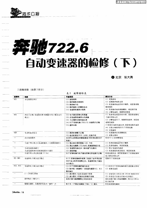
奔驰722.6自动变速器的检修(下)
0 05 2~ 6
02 1 1 、0 3
耍还器处 I ‘ 紧急 仃模 式
( ) 杏 E T控制 I 1柃 C 乜脑的接 火或更换支撑座 ( )更换 变速 器 2
( )安装 零件 号码为 1 0 2 0 0 6 E I 1 4 7 5 0 的 Is ( )榆查是 安装 有话塞I { 弹簧 片 2 五 l 放松连接 『缘 L I 的轴 颈螺帽 、 然后以 I0 m 2N
~
缓慢行驶时 ,从换 档杆 处发出 “ 滴答”声
检 查或更换电磁阀
[ Aut o. 1 8
维普资讯
授
上 图 9 电气检测连接 图
表 4 电 气检 测
序 号 故障码
1 O 2O 3O 40 5 . O 6O 7 0 8 . O 00 】 02 0 03 0 04 0 05 0 06 0 【】 】 2
运行模式 ) ( )E T控 制电脑的接头松动 1 C
( )更换 支撑鹰 2 枪音青 J 的调整情况 ( )柃杏控 制阀动作的 平顺性 1 ( )柃查 电磁阀 ,{ 需 要更换 2 见 ( )修 l变速 器内油 面 1 } i ( )检查 油泵的密封情况 2
电 子 液 压 控 制 元 件
可麓靡因/解决方法
线路 线路 线路 线路 线 路 线路 线路 线路
拆 卸 E T控制 电脑 C 点火开关:O F F 拆卸 E T控制 电脑 C 3 端 于 ( O 地线 ) 2 和 9 号端 f ( 信号线 ) 3 端 ( 0 地线 ) u 9 手 2 号端 子 ( 号线 ) 信 点火开关:OF F 拆卸 E T控制 电脑 C 点火开关:OF F 拆卸 E T控制 电脑 C 点火开 关:O F F
00 2
奔驰汽车二章

P2075
变速箱机械故障
P2076
变速箱非常齿合齿轮有故障
P2077
变速箱档位开关有故障
P2078
变速箱常齿合齿轮有故障
P2079
手动变速箱齿轮失效
P2080
油压过低
P2081
油泵没有建立油压
P2082
电脑N15/6故障(变速箱电脑)
P2083
发动机动力断开控制电脑N15/6
P2023
元件N3/10通过CAN传输发动机扭力电脑信号不可信
P2024
元件N3/10通过CAN传输发动机扭力电脑信号不可信
P2025
元件N3/10通过CAN传输发动机扭力电脑信号不可信
P2026
发动机电脑的CAN讯息不可信
P2027
元件N47-5通过CAN传输的停车灯信号不可信或无信号
P2028
元件N47-5通过CAN传输的停车灯信号不可信或无信号
◎P档锁定
点火开关电脑传输:◎变速箱bus-C点火开关电脑连接bus-B
◎空调工作负荷信号
◎档位位置
三、元件检查
(一)电磁阀的功能及测试:
1-2/4-5档换档电磁阀
1、 作用:控制换档
2、控制:电脑用脉宽调整信号控制电磁阀的搭铁端。控制换档时,电磁阀接通,换档完毕后,电磁阀断电;用脉宽调整控制换档,可以达到换档平滑的作用。
2、控制:电脑用脉宽控制TCC电磁阀的搭铁端,控制TCC的接合。通过调节占空比,使到TCC接合比较平滑,在某些条件下,TCC只有部分接合,允许部分打滑。
3、测试:占空比范围在0-90%;在 TCC ON 时,占空比大约为76%时。 电磁阀的电阻规格为2.0-4.0欧姆。做波形测试时,KOER,当电脑命令TCC工作时,占空比会发生变化,但频率保持不变。
修变速箱需要多少钱之奔驰维修现场一片惨状

开宝马坐奔驰这广为流传的一句话,是的,论驾驶习惯宝马车开起来确实令人痛快,但是车子论坐起来的舒适度还是奔驰略胜一筹。
其实奔驰的变速箱设计与奔驰车坐起来的舒适度也挂钩,所以奔驰变速箱一般很少坏。
以下是一款2000年的奔驰进厂维修。
进厂故障,升档顿挫,车子热了给油不提速,猛踩油门也跑不到多快,仪表报警提示。
经检测进厂维修。
一款奔驰五速自动变速箱722.6的变速箱,这款变速有五个前进挡和一个倒挡组成,这款变速箱装的车还是比较多的,奔驰的E系列,S系类都装这款变速箱,还有牧马人,双龙里边的极个别车型,这是变速箱总成外观照。
车主是一家4S店朋友介绍过来的,因为在这个行业里工作的人都知道,4S修理厂都不修变速箱,一般都是接车把变速箱店里搭下来拿到我们专修的地方修,当然中间也会有中间费产生。
这是拆开油底壳的样子,里边就是油格和机电,这款车的油格在油底壳里边,还有的时候就可以拆开油底壳直接换掉这个油格这个就是变速箱核心的地方,阀体和线板,因为这款变速箱的电脑是外置的,所以阀体上边的塑料就是线板,像这个线板因为经常在变速箱里边经历高温冷却,就会出现开焊,从而报故障码,锁挡,而阀体一般就会造成冲击,顿挫,打滑之类的故障这是拆完机电的样子,剩下的一套机械部分就要从头壳往出拆这个是变速箱的输入轴,就是变速箱的动力靠发动机传递到变矩器再通过变矩器传递到变速箱里边,一般变速箱缺油了或者离合器泄压了,最先烧蚀的就是输入轴这个是一个离合器的正面照,拆完钢片和摩擦片之后的的样子,里边就是离合器活塞,,这个胶圈时间长就会老化,变硬,从而泄压这组就是输入轴的摩擦片和钢片,像这种摩擦片都是一些特殊材料站在一起,时间长就会磨薄,进水的话就会脱胶,导致特殊材料掉皮.这一组是倒挡离合器的钢片加磨片.原理都一样,摩擦片都是一颗颗细小颗粒在高温高压情况下形成的,里程数高的车子摩擦片表面发生容易磨损就会脱落,那么变速箱就容易形成打滑症状。
这是变速箱里边的机械东西,分为输入轴离合器,倒挡离合器,高速档离合器,还有行星架,太阳轮,单向离合器,油泵,每个变速箱里边的东西都是大同小异,有的离合器多,有的行星架比较多,但都是每个部件都不能缺少,不然就实现不了档位的变化。
BENZ 722.6 变速器原理

换档电磁阀y36y3
换档电磁阀y36y4 换档电磁阀y36y5 TCC电磁阀y36y6 调节压力调节电磁阀y36y1
换档压力调节电磁阀y36y2
诊断信号
Service ●Training
自动变速器
(二)4、220底盘变速箱CAN构成
Service ●Training
自动变速器
(二)5、220底盘变速箱CAN信号说明
Service ●Training
电
脑 N15/5
自动变速器
(二)9、220、215选档杆 P位置功能
Service ●Training
自动变速器
(二)10、220、215选档杆移不动的可能原因
1、驾驶员识别系统没有授权(DI—EWM)
2、刹车开关没踩下(来自DI电脑) 3、选挡杆电脑不工作(电源、搭铁)
Service ●Training
自动变速器
注2:油面控制功能说明
Service ●Training
自动变速器
二、电控变速箱电路控制系统说明
(一)、无手控换档变速器电脑控制系统原理
(二)、带手控换档电脑控制系统原理
(三)、线路识别及电控元件检测方法、数据
Service ●Training
自动变速器
电控自动变速箱722.6xx
黄林彬 制作
自动变速器
BENZ自动变速箱型号识别
220 270 0602 722. 618 0 2 000456
系列号 自动波箱 左方向车 波箱型号 零件编码
722 . 6 18
波箱号码,依据底盘、引擎不 同而相应变化
变速箱号码,如:W5A580
轿车自动变速箱
Service ●Training
奔驰722.9自动变速箱维修手册(英文)
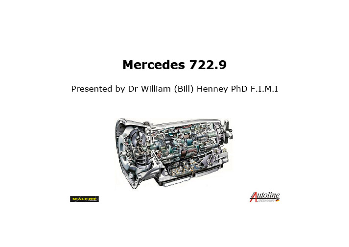
Mercedes 722.9Presented by Dr William (Bill) Henney PhD F.I.M.IFeatures•Electronically Controlled Automatic Gearbox•7 Forward and 2 Reverse Gears•Transmission Control Module is :Integrated into the Valve Body and is “Flash”Capable•Torque Converter operates in Open and Slip Mode in all 7 Forward Gears•Gear Ratios achieved with 3 Clutches and 4 Brakes (No Free-Wheeling Units)•3 Planetary Gearsets2–Simple and 1-RavigneauxAdvantages•Shift comfort and driving pleasure enhanced through improved control of gear changes.1.Shorter computer reaction time by 0.1 second2.Downshifts shortened by up to 0.2 second3.Coast downshifts shortened by 0.4 -2.5 seconds •Fuel consumption improved by 4%•Noise level reduced due to lower engine speeds in higher gears.•Flexible adaptation to engine and vehicle.Transmission Applications •Currently only one size of 722.9 will be produced. Asmaller version W7A 700 has been postponed until further notice.•The transmission is also referred to as :NAG 2 (New Automatic Gearbox 2)7 G-Tronic•First installed in Non 4matic 2004 year -M113 engine vehicles. S430 –S500 –CL500 –E500 –SL500•722.6 Transmission (NAG 1 or NAG V) will continue to be built until 2012Variable Shift Programming •Just like the 722.6 it has two basic shift programs using the S/C button on the ESM Electronic Shifter Module.“S”(Sport) “C”(Comfort)1st Gear Starts 2nd Gear StartsNormal Shift Points Earlier Upshifts/Later Downshifts Reverse ratio -3.416:1 Reverse ratio -2.231:1•The Transmission will start in 1st gear if any of the following conditions apply:1st gear is manually selected75% of full throttle acceleration from start Cold Engine Temperature (Pre-Catalytic warm-up)Transmission FluidIt is suggested a new fluid should be used referred to as ATF3353. This has a higher thermal stability andfriction consistency.This fluid can be used on 722.3/4/5/6It requires no scheduled maintenance.Supplied by Shell & Fuchs Europein 1 Litre containers.Mercedes Part No. A001 989 45 03 10Transmission Fluid Level •No Dipstick or Dipstick tube.•Fluid level check using overflow method.•Oil pan has overflow pipe clipped onto the pan above drain plug.•Fluid level must be checked at specified temperature.NEWOLDPan depth +3mmOverflow pipe +13.5mm Transmission Fluid Level•A new oil pan is used and can be identified by its design and Part No. 220 270 09 12•The white overflow pipe has been increased in length and as a result will hold an extra 0.2 litres of fluid.Major ComponentsMajor Component Legend1.Park Pawl2.Turbine wheel3.Stator4.Impeller5.Transmission Breather6.Oil pump7.B1 Brake8.K1 Clutch9.Ravigneaux Gearset10.B3 Brake11.K2 Clutch12a. Front Simple Planetary12b. Rear Simple Planetary 13.BR Brake 14.K3 Clutch 15.B2 Brake 16.Torque Converter Clutch 17.Torque Converter housing 18.Output speed exciter ring 19.Internal speed ring magnet 20.Turbine speed ring magnet 21.Electro-hydraulic control unit 22.Range Selector LeverTorque Converter1.Lock-up with torsional damper springs 2.Turbine wheel 3.Stator 4.Impeller•Same as used in some 722.6 transmissions •Fluid capacity 4 Litres •Lock-up can be activated in all 7 gears •Incorporates damper springs to reduce vibrationTorque Converter•The Torque Converter is never fully locked•In 1st and 2nd gears if throttle and output speed are in zone A the Torque converter is openIf throttle and outputspeed are in zone B itoperates in slip-mode in all 7 forward gears•If temperature exceeds 140 Deg C the TCC is switched off and lower gear selected. (DTC 2226)BA N D A = OPEN N = OUTPUT SPEEDB = SLIP-MODE D = % THROTTLE•Torque converter housing is die-cast Aluminium •Transmission is die-cast magnesium (2Kg weight reduction)•New aluminium bolts must be used if removed and tightening torques should be adhered to•Thread repairs to magnesium case is permissibleTransmission HousingTransmission Housing •Housing gasket is made from aluminium sheet coated with elastomer and can be re-used•The gasket has a lipthat faces forwardto direct water awayfrom the casing•Salt water can damagemagnesium in as littleas 8 weeksOil Cooler Pipes•The transmission cooler pipes are sealed with an O’ring and retainedusing a boltOil Pump•This transmission as like the 722.6 uses a crescent style pump•The suction side has a recess to help reduce oil intake noise. This is also expected to be phased in on the 722.6•To improve performanceat high temperatures andalso reduce weight it isexpected that the pumpand gears will soon bemade from aluminiumRavigneaux Gear Set•The advantages of the Ravigneaux Gear set are that it combines two simple planetary sets into one simple unit•It increases available gear ratios compared to a simple planetary set. It has two ring gearsShort planetary gearLong planetary gearSun gearPlanetary gear carrierSmall ring gearLarge ring gearRavigneaux Gear Set•The input from the torque converter turbine arrives at the gear set via the small ring gear•The long planetary gear transfers drive via the the sun gear or short planetary gear depending upon the applied memberShort Planetary GearLong Planetary GearSun GearPlanetary Gear CarrierSmall Ring GearLarge Ring GearMulti -Disc Brakes•B1 & B3 Multi-disc brakes use single sided platesB1B3BRB2Outer teethInner teethMulti -Disc Clutches •All multi-disc clutches use single sided platesOuter teethInner teeth K1K2K3Shift Application ChartXXX-2.231R(2)X X X-3.416R(1)X X N(1)X XX 0.7287X X X0.8206X X X1.0005X X X 1.3684X X X 1.9213X X X2.8592X XX 4.3771K3K2K1BR B3B2B1RATIOGEAR (1) = S Mode (2) = C Mode•In neutral 2 elements are applied, so only 1 element needs to apply when selecting either D or R •A gear change is made by applying an element whilst disengaging anotherPower Flow 1st GearPower Flow 2nd GearPower Flow 3rd GearPower Flow 4th GearPower Flow 5th GearPower Flow 6th GearPower Flow 7th GearPower Flow Reverse (S mode)Power Flow Reverse (C mode)Shift Sequences•In addition to sequentially shifting the 722.9 can downshift skipping gears providing the one element applied, one element released principleXX X 1st X X X 2ndX X X 3rdX X X 4thX X X 5thX X X 6thX X X 7thK3K2K1B3B2B1Electro-hydraulic Module •Uses same principle as 722.6 of controlling hydraulics with electronics•The module will adapt for optimal shift quality •Mounted to the Valve body are components that control, monitor and enable the gear shiftsElectro-hydraulic ModuleElectro-hydraulic Module •Each Valve body is individually tested•Hydraulic pressures and currents are measured •Values are evaluated and corresponding algorithms are written to the modules permanent memory •This ensures that the module is calibrated to that valve body•Once this process is complete the valve body is installed in the transmissionElectric Control Module •The task of the Electric Control module is to -Evaluate various input signalsCalculate shift points according to programming Evaluate gear shifts and attempt to adaptActivate 8 control solenoid valvesTemperatureSensor“Flashable”capable software using SDS / DASElectric Control Module•As the control module is integrated into the valve body, wiring to the transmission has been greatly reduced•Electrical plug has only 5pins1.= CAN C High2.= CAN C Low3.= To diagnostic X11/44.= Circuit 87 (relay & fuse)5.= Circuit 31Electric Control Module •The plug connector is sealed by two O’rings and one square section sealPlug connectorO’RingsSquare section sealElectric Control ModuleY3/8n3 Output speed sensorY3/8n1 Input speed sensorY3/8n2 Internal speed sensorY3/8s1 Range selector sensor 11Electrical connector X11/4 Diagnostic socket Y3/8n4 Electric control module Y3/8y1 –Y3/8y8 SolenoidsInformation Received Over CAN C1.Engine RPM2.Engine coolant temperature3.Throttle pedal position4.Engine load5.ESP signals6.Cruise control signals7.ESM (Shifter position)Information Received Directly1.Speed sensors2.Range selector sensor3.Transmission fluid temperatureSpeed Sensors Y3/8n1 & n2•Front speed sensor (Y3/8n1) monitors turbine speed (input shaft/ small ring gear)•Centre speed sensor (Y3/8n2) monitors Ravigneaux planet carrier speed•These sensors are Active speed sensors•They permit a signal to be read through other Non-ferrous parts•The magnets are moulded in plastic rings and secured inside aluminium flangesRing magnet Parking gearExciter ringTurbine sensorInternalsensorOutput sensor Integrated ringmagnetSpeed Sensors Y3/8n1 & n2Y3/8n2Y3/8n1Speed Sensor Y3/8n3Ring magnet Parking gearExciter ringTurbine sensorInternalsensorOutput sensor Integrated ringmagnet•The Y3/8n3 sensor measures transmission output speed from a ring attached to the park gear •It is a Hall effect type sensor•Replaces wheel speed information previously used to calculate shift points and detects gear slip •Direct input to electric control module•Improves reaction time to changes in vehicle speedSolenoid Valves•The solenoids are actuated by the transmission control module using variable current•Each solenoid valve has a filter screen fitted•The 4 solenoids shown are normally closed. No current / no pressure. Pressure increases with currentB2 Brake TCC ValveB3 Brake K1 ClutchSolenoid Valves•The valves shown are normally open. They produce maximum pressure with no current applied and decrease pressure with current•These valves are responsible for limp-home mode when all valves are de-energisedK2 Clutch Pressure RegulatorK3 ClutchB1 BrakeHydraulic Diagram Shown in 2nd gearHydraulic Diagram LegendRange Selector Sensor (Y38s1)•The sensor is soldered onto the ribbon cable of the electric control module•This sensor cannot be replaced separately•It records the position of the range selection lever•It is a PLCD, Permanent magnetic Linear Contactless Displacement sensor•It is constructed of a soft magnetic core surrounded by a wire along it’s length with additional coil at each end•It has a permanent magnet on the range selector valve which changes it’s magnetic fieldand output voltageof the sensorWARNINGThis sensor must be“learned in”or Limp-homewill occurFluid Level Control•This feature reduces the possibility of gear sets running in fluid and causing ATF foaming •Two floats are used because the transmission is 41mm longer than the 722.6 and fluid has a tendency to run to the front of the case under sharp brakingFront level floatRear level floatCheck and Diagnosis•Oil Level Check•Limp-home Modes•DTC’s•EDAC•Replacement of Transmission or Control Module•SCN & CVN CodingFluid Level9.7 Litres 9.5 Litres Fluid fill total 40 –45 Deg C 30 –35 Deg C Level check40 Deg C 30 deg C Initial fill checkS127.00-P-0002B S127.00-P-0002A WIS document No.New pan Design Old Pan Design•The fluid level should be checked a specific fluid temperatures using SDS / DAS•There are two different oil pan designs with different fill specifications •Mercedes recommend using a special filling tool to add fluid via the drain bung。
奔驰S600高速无法行驶

58·July-CHINA 栏目编辑:王高明 ******************奔驰S600高速无法行驶◆文/北京 柳泉冰故障现象一辆奔驰W220S600轿车,搭载奔驰公司生产型号为722.6系列的五速变速器。
据客户反映,该车在行驶过程中发动机转速和车速不匹配(发动机转速过高),怀疑变速器打滑。
故障诊断与排除询问用户后得知,该车的变速器故障很久以前就出现了,最初的故障是3挡升4挡的时候偶尔打滑,在其他修理厂检查后给出的维修报价太高,就一直没有维修。
因为此变速器采用了全电子控制,出故障时变速器控制单元有时会进入应急运行模式,变速器的挡位就会锁定在2挡,此时用户就会将汽车开到修理厂进行故障码的清除,这样车辆就会继续使用一段时间。
但是从最近几天开始,行驶中变速器一旦进入高速挡就出现严重打滑现象,此时变速器系统内部就会存储故障码并且进入应急运行模式状态。
将故障码清除后,一旦行驶进入高速挡就开始打滑,车辆将无法继续行驶,用户只好进场维修。
首先要先了解一下这款变速器的情况,722.6系列变速器也称为W5A580变速器,奔驰C级,E级以及S级车辆上均配置了此系列变速器。
变速器的控制单元安装在发动机舱内右后侧的控制单元盒内,变速器的变矩器内带有锁止离合器,各挡位的传动比由3组行星齿轮机构决定。
变速器内部换挡执行元件有3组多片式离合器,3组多片式制动器以及两组单向离合器,不同的离合器和制动器组合工作可以获得5个前进挡和2个倒挡(高速倒挡和低速倒挡,通过驾驶员控制加速踏板的控制自动切换),五挡是超速挡。
了解变速器的基本情况后,着手进行检查。
首先进行路试,故障现象确实如客户所说,变速器打滑现象很严重,而且行驶中还出现锁挡的现象。
使用奔驰原厂的故障诊断仪STAR清楚故障码后继续行驶又会锁挡,采用手动模式从1挡到3挡的过程中有轻微打滑的现象,如果进入四挡就会出现严重打滑现象。
回到厂里进行基本检查,变速器油位正常(变速器没有油尺,可以用专用工具来进行测量),目测变速器外部没有漏油的痕迹,换挡杆调节也正常。
浅析奔驰9速自动变速器725.0的结构与动力传输流程
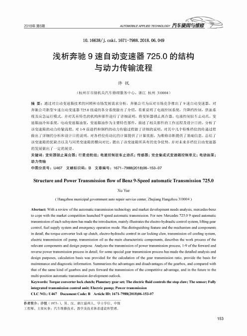
2018年第6期AUTOMOBILE APPLIED TECHNOLOGY10. 16638/ki. 1671-7988. 2018. 06. 049浅析奔驰9速自动变速器725.0的结构与动力传输流程许悦(杭州市市级机关汽车修理服务中心,浙江杭州310004)摘要:通过对自动变速箱技术的回顾和市场发展需求分析,奔驰公司为应对市场竞争推出了9速自动变速器。
对 奔驰公司新型9速自动变速器725.0组成的各分系统做出了介绍,着重说明了电液控制系统,升降档控制,供油系 统及应急运行模式。
并对其有特色的机构和部件进行了详细说明,将变矩器锁止离合器,电液控制驻车止动爪,变 速箱油冷却系统,电动变速箱油泵,变速箱油作为主要特色部件,描述了相关部件的工作过程及设计目的。
分析了 该变速箱的动力传输流程,对1-9前进档和倒档的动力传输过程做了详细的说明,对其中几个特殊档位的传递过程 做出了详细的分析和设计目的说明,对各档位传动比的计算提供了计算依据,为维修诊断提供了基础信息。
总结了 该变速箱的优缺点以及与同类变速箱的横向对比,提出了该变速箱所具有的竞争优势,并对未来多档位自动变速器 的发展做出了一定的展望。
关键词:变矩器锁止离合器;行星齿轮组;电液控制驻车止动爪;传感器;完全集成式变速箱控制单元;电动油泵;动力传输中图分类号:U467文献标识码:B文章编号:1671-7988(2018)06-153-07Structure and Power Transmission flow of Benz 9-Speed automatic Transmission 725.0XuYue(Hangzhou municipal government auto repair service center, Zhejiang Hangzhou 310004 )Absrtact: With a review of the automatic transmission technology and market development needs analysis, mercedes-benz to cope with the market competition launched 9 speed automatic transmission. For new Mercedes 725.0 9 speed automatic transmission of each subsystem has made the introduction, mainly illustrates the electro-hydraulic control system, lifting gear control, fuel supply system and emergency operation mode. Has distinguishing feature and the mechanism and components in detail, the torque converter lock up clutch, electro-hydraulic control in car locking claw, transmission oil cooling system, electric transmission oil pump, transmission oil as the main characteristic components, describes the work process of the relevant components and design purpose. Analyzes the transmission of power transmission process, 1-9 of the forward and reverse power transmission process in detail, for some special gear transmission process has made the detailed analysis and design purposes, calculation basis was provided for the calculation of the gear transmission ratio, provide the basis for maintenance and diagnostic information. Summarizes the advantages and disadvantages of the gearbox, and compared with that of the same kind of gearbox and puts forward the transmission of the competitive advantage, and in the future to the multi-position automatic transmission development outlook.Keywords: Torque converter lock clutch; Planetary gear set; The electric fluid controls the stop claw; The sensor; Fully integrated transmission control unit; Electric pump; Power transmissionCLC NO.: U467 Document Code: B Article ID: 1671-7988(2018)06-153-07作者简介:许悦(1973-),男,汉,浙江温州人,学士学位,中级工程师,主要从事:汽车维修技术,教学及技术体系建设和管理。
自动变速器-奔驰722

D挡主 油路
8号B2/BR 换挡阀
单向阀
节流孔
19号手动 控制阀
K3离合器 结合
搭载奔驰722.9自动变速器的车型
奔驰CL500(左)与奔驰SL500(右)都是搭载722.9自动变速箱 722.9自动变速箱从2003年开始装车,至今仍有搭载在现有车型,可谓
历史悠久,传承者奔驰的历史。
基本参数——奔驰722.9档位执行元件表
基本参数
电磁阀油路板
电磁阀板总成,有8个电磁阀,
基本参数
D1挡油路分析——工作元件表
D1挡油路分析——分析流程图
手动阀置 于D挡
TCM
电磁阀1通电 电磁阀2通电 电磁阀3通电 电磁阀4断电
油压建立 关闭 关闭 关闭
推动22号球 阀堵住下口
电磁阀5断电 电磁阀6通电 电磁阀7通电 电磁阀8断电
接通 接通 关闭 关闭
15号阀芯右移 5号阀芯下移
9号阀芯下移 8号阀芯上移
4
B1/B3减压控制阀
14
5
B3换挡控制阀
15
6
K3油压减压控制阀
16
7
B2油压减压控制阀
17
8
B2/BR换挡阀
18
9
K2油压减压控制阀
19
10
失效保护换挡阀
20
K2换挡油压调节阀 润滑油压调节阀
锁止离合器转换阀 锁止油压调节阀
K3换挡油压调节阀 电磁阀油压调节阀 电磁阀油压调节阀 B2/BR减压控制阀
P/N挡油路分析——电磁阀油路分析
P/N 挡主 油路
电磁 阀油 压调 节油 路
3号电磁阀断 电供油
5号电磁 阀打开
- 1、下载文档前请自行甄别文档内容的完整性,平台不提供额外的编辑、内容补充、找答案等附加服务。
- 2、"仅部分预览"的文档,不可在线预览部分如存在完整性等问题,可反馈申请退款(可完整预览的文档不适用该条件!)。
- 3、如文档侵犯您的权益,请联系客服反馈,我们会尽快为您处理(人工客服工作时间:9:00-18:30)。
电磁阀
电磁阀工作表---1
GEAR/ACTION Park P-to-R Transition Reverse R-to-N Transition Neutral N-to-D (1st) Transition 1st 1st-to-2nd Transition 2nd 2nd-to-3rd Transition MODULATING PRESSURE CONTROL REG MOD REG REG REG REG MOD MOD MOD MOD SHIFT PRESSURE CONTROL REG MOD ON MOD REG MOD ON MOD ON MOD 1–2/4–5 SHIFT OFF OFF OFF OFF OFF OFF OFF ON OFF OFF 3–4 SHIFT ON ON OFF ON ON ON OFF OFF OFF OFF 2–3 SHIFT OFF OFF OFF OFF OFF OFF OFF OFF OFF ON TORQUE CONVERTER CLUTCH OFF OFF OFF OFF OFF OFF OFF OFF OFF OFF
电磁阀工作表---2
GEAR/ACTION 5th-to-4th Transition 4th 4th-to-3rd Transition 3rd 3rd-to-2nd Transition 2nd MODULATING PRESSURE CONTROL MOD MOD MOD MOD MOD MOD SHIFT PRESSURE CONTROL MOD ON MOD ON MOD ON 1–2/4–5 SHIFT ON OFF OFF OFF OFF OFF 3–4 SHIFT OFF OFF ON OFF OFF OFF 2–3 SHIFT OFF OFF OFF OFF ON OFF TORQUE CONVERTER CLUTCH OFF OFF OFF OFF OFF OFF
TC Pressure Limit Valve 2–3 Overlap Valve
Solenoid Valve Cap Solenoid Valve Cap Bolt (M6X32) Bolt (M6X30)
8 9 10 11
3–4 Shift Solenoid Valve TCC Solenoid Valve 1–2/4–5 Shift Solenoid Valve 2–3 Shift Solenoid Valve
3rd
3rd-to-4th Transition 4th 4th-to-5th Transition 5th
MOD
MOD MOD MOD MOD
ON
MOD ON MOD ON
OFF
OFF OFF ON OFF
OFF
ON OFF OFF OFF
OFF
OFF OFF OFF OFF
OFF
OFF OFF OFF OFF
2nd-to-1st Transition
1st 1st-to-N Transition Neutral N-to-R Transition
MOD
MOD REG REG REG
MOD
ON REG REG MOD
ON
OFF OFF OFF OFF
OFF
OFF ON ON ON
OFF
OFF OFF OFF OFF
722.6自动变速器培训
奔驰722.6自动变速器
概述
• 722.6变速器是奔驰公司自主研发的5前速全电子 控制变速器。主要应用在96年以后的大部分车型 中。 • 该变速器控制单元是根据接收变速器内的两个速 度传感器与控制器区域网络(CAN)提供的加速 踏板位置、车速、发动机转速、变速器温度等信 息进行综合分析,并通过3个换档电磁阀、2个压 力调节阀及1个TCC锁止控制电磁阀来决定控制升 档还是降档的换档时机以及变扭器锁止离合器接 合与分离时机的。
选档杆功能
722.6机械部件的组成
1 2 3
B1 Brake K1 Clutch K2 Clutch
5 6 7
K3 Clutch B2 Brake F2 Overrunning Clutch
4
B3 Brake
8
F1 Overrunning Clutch
换档执行元件排列顺序
电磁阀位置说明
1 2 3 4
5
6 7
Leaf Spring
Modulating Pressure Solenoid Valve Shift Pressure Regulating Solenoid Valve
12
13
Lead Frame
Upper Valve Body (Shift Plate)
电磁阀的作用
• y36y3:控制变速器1-2档和4-5档;(电磁阀在 换档的瞬间工作,换档完毕后电磁阀处于OFF状 态); • y36y4:控制变速器的2-3档;(电磁阀在换档的 瞬间工作,换档完毕后电磁阀处于OFF状态); • y36y5:控制变速器的3-4档。(电磁阀在换档的 瞬间工作,换档完毕后电磁阀处于OFF状态); • y36y1:用于控制变速器的工作压力; • y36y2:用于控制变速器换档时的换档压力; • y36y6:用于控制锁止离合器的工作。 • 注:所有电磁阀的工作均为百分比控制
阀体---1
1
Upper Valve Body
6
3–4 Overlap Valve
2
3 4 5
Manual Valve
3–4 Holding Pressure Shift Valve 3–4 Command Valve 3–4 Shift Pressure Shift Valveressure Regulating Valve
OFF
OFF OFF OFF OFF
Reverse
R-to-P Transition Park REG = Constant Pressure OFF = Zero Pressure
MOD
REG REG
ON
REG REG
OFF
OFF OFF
OFF
ON ON
OFF
OFF OFF
OFF
OFF OFF
ON = Regulated Line Pressure MOD = Modulating Pressure