土木工程中英文翻译
土木工程专业英语单词

1 Civil engineering 土木工程。
2 Slopes and fills 边坡和路堤3 waterfront 河流湖泊4 settlement 沉降5 stability 稳定性坚固,耐久性 5 hydraulic 水利的,液压的7 runoff 流量,流放8 behavior 性能性质9sanitize 使清洁,除掉有害物10 dump 垃圾堆11 waste 废弃物12 hazardous 危险的14 major 专业科目15 cultivable 可耕的,可培养的16 remedy 补救,修理17 roadway 路面道路18 hurricane 飓风19asphalt 沥青20 concrete 混凝土21 combustible 易燃的22 slurry 泥浆1 execution 施工,实施,执行2 specific 特殊的,专门的具体的3 dynamic 动力的,冲击的4characteristic 特有的,特性性能5 intensity 强度,密度6 sump 排水坑7 carbon 碳纤维8 novel 新的,异常的9 excavation 挖掘,开挖10landscape 风景,美化11 fill 填土12 ancillary 辅助的,附属的13 foundation 基础14 excavator 挖掘机15 proceed 继续进行,开始16 interlock 使连接,使结合17 construction 建造,施工18 Surveyor 测量员19 dewater 排水20 placement and curing 浇筑与养护21superstructure 上部结构22duration 持续时间23 destroy 破坏,毁坏24 initially 最初,开始1 jurisdiction 权限,管辖权2 bar 法庭律师的职业3 curriculum 课程学习计划4 statistic 统计学5 persuasive 有说服力的6 recruit 补充,招收7 science Orient 注重科学的8 specialize 专门研究。
土木工程的英文是Civil Engineering
土木工程的英文是Civil Engineering ,直译是民用工程,它是建造各种工程的统称。
它既指建设的对象,即建造在地上,地下,水中的工程设施,也指应用的材料设备和进行的勘测、设计施工、保养维修等专业技术。
土木工程随着人类社会的进步而发展,至今已经演变成为大型综合性的学科,它已经出许多分支,如:建筑工程,铁路工程,道路工程,桥梁工程,特种工程结构,给水排水工程,港口工程,水利工程,环境工程等学科。
土木工程共有六个专业:建筑学,城市规划,土木工程,建筑环境与设备工程,给水排水工程和道路桥梁工程。
土木工程作为一个重要的基础学科,有其重要的属性:综合性,社会性,实践性,统一性。
土木工程为国民经济的发展和人民生活的改善提供了重要的物质技术基础,对众多产业的振兴发挥了促进作用,工程建设是形成固定资产的基本生产过程,因此,建筑业和房地产成为许多国家和地区的经济支柱之一。
古代的土木工程有很长的时间跨度,大致从公元前500年新石器时代出现原始的土木工程活动到16世纪末意大利的文艺复兴,导致土木工程走上迅速发展的道路为止,前后经历了两千多年。
在这段时间内,由于科学理论发展及其缓慢,土木工程也没有突破习惯的发展。
远古时代,居住和交往的需要,人类开始了掘土为穴,架木为桥的原始的土木工程活动,我国黄河流域的仰邵文化遗址和西安半坡遗址发现了有供居住的浅穴和直径为5—6米的圆形房屋。
中国古代的建筑多采用木结构,并逐渐形成与此想适应的风格,公元14世纪的建造的北京故宫是世界上最大的最完整的古代木结构宫殿建筑群,应县的木塔是世界上最高的木建筑。
与此同时,欧洲的以石拱结构为主的古代房屋建筑也达到了很高的水平,意大利的比萨大教堂,法国的巴黎圣母院,罗马的圣彼得大教堂均反映了欧洲这一时期建筑施工和结构的最高成就。
从17世纪中页开始到20 世纪40年代第二次世界大战结束为止的300年间,国外的建筑取得了长足的进步。
土木工程进入了定量分析阶段。
土木工程英文文献及翻译
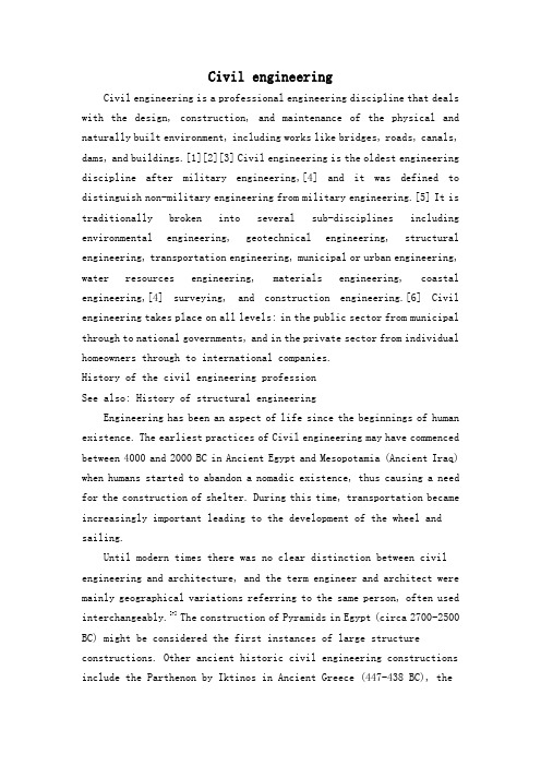
Civil engineeringCivil engineering is a professional engineering discipline that deals with the design, construction, and maintenance of the physical and naturally built environment, including works like bridges, roads, canals, dams, and buildings.[1][2][3] Civil engineering is the oldest engineering discipline after military engineering,[4] and it was defined to distinguish non-military engineering from military engineering.[5] It is traditionally broken into several sub-disciplines including environmental engineering, geotechnical engineering, structural engineering, transportation engineering, municipal or urban engineering, water resources engineering, materials engineering, coastal engineering,[4] surveying, and construction engineering.[6] Civil engineering takes place on all levels: in the public sector from municipal through to national governments, and in the private sector from individual homeowners through to international companies.History of the civil engineering professionSee also: History of structural engineeringEngineering has been an aspect of life since the beginnings of human existence. The earliest practices of Civil engineering may have commenced between 4000 and 2000 BC in Ancient Egypt and Mesopotamia (Ancient Iraq) when humans started to abandon a nomadic existence, thus causing a need for the construction of shelter. During this time, transportation became increasingly important leading to the development of the wheel and sailing.Until modern times there was no clear distinction between civil engineering and architecture, and the term engineer and architect were mainly geographical variations referring to the same person, often used interchangeably.[7]The construction of Pyramids in Egypt (circa 2700-2500 BC) might be considered the first instances of large structure constructions. Other ancient historic civil engineering constructions include the Parthenon by Iktinos in Ancient Greece (447-438 BC), theAppian Way by Roman engineers (c. 312 BC), the Great Wall of China by General Meng T'ien under orders from Ch'in Emperor Shih Huang Ti (c. 220 BC)[6] and the stupas constructed in ancient Sri Lanka like the Jetavanaramaya and the extensive irrigation works in Anuradhapura. The Romans developed civil structures throughout their empire, including especially aqueducts, insulae, harbours, bridges, dams and roads.In the 18th century, the term civil engineering was coined to incorporate all things civilian as opposed to military engineering.[5]The first self-proclaimed civil engineer was John Smeaton who constructed the Eddystone Lighthouse.[4][6]In 1771 Smeaton and some of his colleagues formed the Smeatonian Society of Civil Engineers, a group of leaders of the profession who met informally over dinner. Though there was evidence of some technical meetings, it was little more than a social society.In 1818 the Institution of Civil Engineers was founded in London, and in 1820 the eminent engineer Thomas Telford became its first president. The institution received a Royal Charter in 1828, formally recognising civil engineering as a profession. Its charter defined civil engineering as:the art of directing the great sources of power in nature for the use and convenience of man, as the means of production and of traffic in states, both for external and internal trade, as applied in the construction of roads, bridges, aqueducts, canals, river navigation and docks for internal intercourse and exchange, and in the construction of ports, harbours, moles, breakwaters and lighthouses, and in the art of navigation by artificial power for the purposes of commerce, and in the construction and application of machinery, and in the drainage of cities and towns.[8] The first private college to teach Civil Engineering in the United States was Norwich University founded in 1819 by Captain Alden Partridge.[9] The first degree in Civil Engineering in the United States was awarded by Rensselaer Polytechnic Institute in 1835.[10] The first such degree to be awarded to a woman was granted by Cornell University to Nora Stanton Blatchin 1905.History of civil engineeringCivil engineering is the application of physical and scientific principles, and its history is intricately linked to advances in understanding of physics and mathematics throughout history. Because civil engineering is a wide ranging profession, including several separate specialized sub-disciplines, its history is linked to knowledge of structures, materials science, geography, geology, soils, hydrology, environment, mechanics and other fields.Throughout ancient and medieval history most architectural design and construction was carried out by artisans, such as stone masons and carpenters, rising to the role of master builder. Knowledge was retained in guilds and seldom supplanted by advances. Structures, roads and infrastructure that existed were repetitive, and increases in scale were incremental.[12]One of the earliest examples of a scientific approach to physical and mathematical problems applicable to civil engineering is the work of Archimedes in the 3rd century BC, including Archimedes Principle, which underpins our understanding of buoyancy, and practical solutions such as Archimedes' screw. Brahmagupta, an Indian mathematician, used arithmetic in the 7th century AD, based on Hindu-Arabic numerals, for excavation (volume) computations.[13]Civil engineers typically possess an academic degree with a major in civil engineering. The length of study for such a degree is usually three to five years and the completed degree is usually designated as a Bachelor of Engineering, though some universities designate the degree as a Bachelor of Science. The degree generally includes units covering physics, mathematics, project management, design and specific topics in civil engineering. Initially such topics cover most, if not all, of thesub-disciplines of civil engineering. Students then choose to specialize in one or more sub-disciplines towards the end of the degree.[14]While anUndergraduate (BEng/BSc) Degree will normally provide successful students with industry accredited qualification, some universities offer postgraduate engineering awards (MEng/MSc) which allow students to further specialize in their particular area of interest within engineering.[15]In most countries, a Bachelor's degree in engineering represents the first step towards professional certification and the degree program itself is certified by a professional body. After completing a certified degree program the engineer must satisfy a range of requirements (including work experience and exam requirements) before being certified. Once certified, the engineer is designated the title of Professional Engineer (in the United States, Canada and South Africa), Chartered Engineer (in most Commonwealth countries), Chartered Professional Engineer (in Australia and New Zealand), or European Engineer (in much of the European Union). There are international engineering agreements between relevant professional bodies which are designed to allow engineers to practice across international borders.The advantages of certification vary depending upon location. For example, in the United States and Canada "only a licensed engineer may prepare, sign and seal, and submit engineering plans and drawings to a public authority for approval, or seal engineering work for public and private clients.".[16]This requirement is enforced by state and provincial legislation such as Quebec's Engineers Act.[17]In other countries, no such legislation exists. In Australia, state licensing of engineers is limited to the state of Queensland. Practically all certifying bodies maintain a code of ethics that they expect all members to abide by or risk expulsion.[18] In this way, these organizations play an important role in maintaining ethical standards for the profession. Even in jurisdictions where certification has little or no legal bearing on work, engineers are subject to contract law. In cases where an engineer's work fails he or she may be subject to the tort of negligence and, in extreme cases, thecharge of criminal negligence.[citation needed] An engineer's work must also comply with numerous other rules and regulations such as building codes and legislation pertaining to environmental law.CareersThere is no one typical career path for civil engineers. Most people who graduate with civil engineering degrees start with jobs that require a low level of responsibility, and as the new engineers prove their competence, they are trusted with tasks that have larger consequences and require a higher level of responsibility. However, within each branch of civil engineering career path options vary. In some fields and firms, entry-level engineers are put to work primarily monitoring construction in the field, serving as the "eyes and ears" of senior design engineers; while in other areas, entry-level engineers perform the more routine tasks of analysis or design and interpretation. Experienced engineers generally do more complex analysis or design work, or management of more complex design projects, or management of other engineers, or into specialized consulting, including forensic engineering.In general, civil engineering is concerned with the overall interface of human created fixed projects with the greater world. General civil engineers work closely with surveyors and specialized civil engineers to fit and serve fixed projects within their given site, community and terrain by designing grading, drainage, pavement, water supply, sewer service, electric and communications supply, and land divisions. General engineers spend much of their time visiting project sites, developing community consensus, and preparing construction plans. General civil engineering is also referred to as site engineering, a branch of civil engineering that primarily focuses on converting a tract of land from one usage to another. Civil engineers typically apply the principles of geotechnical engineering, structural engineering, environmental engineering, transportation engineering and construction engineering toresidential, commercial, industrial and public works projects of all sizes and levels of construction翻译:土木工程土木工程是一个专业的工程学科,包括设计,施工和维护与环境的改造,涉及了像桥梁,道路,河渠,堤坝和建筑物工程交易土木工程是最古老的军事工程后,工程学科,它被定义为区分军事工程非军事工程的学科它传统分解成若干子学科包括环境工程,岩土工程,结构工程,交通工程,市或城市工程,水资源工程,材料工程,海岸工程,勘测和施工工程等土木工程的范围涉及所有层次:从市政府到国家,从私人部门到国际公司。
土木工程常用英语翻译
土木工程常用翻译工程结构 buildin g and civil enginee ring structu res房屋建筑和土木工程的建筑物、构筑物及其相关组成部分的总称。
工程结构设计designof buildin g and civil enginee ringstructu res在工程结构的可靠与经济、适用与美观之间,选择一种最佳的合理的平衡,使所建造的结构能满足各种预定功能要求。
房屋建筑工程buildin g enginee ring一般称建筑工程,为新建、改建或扩建房屋建筑物和附属构筑物所进行的勘察、规划、设计、施工、安装和维护等各项技术工作和完成的工程实体。
土木工程 civil enginee ring除房屋建筑外,为新建、改建或扩建各类工程的建筑物、构筑物和相关配套设施等所进行的勘察、规划、设计、施工、安装和维护等各项技术工作和完成的工程实体。
公路工程 highway enginee ring为新建或改建各级公路和相关配套设施等而进行的勘察、规划、设计、施工、安装和维护等各项技术工作和完成的工程实体。
铁路工程 railway enginee ring为新建或改建铁路和相关配套设施等所进行的勘察、规划、设计、施工、安装和维护等各项技术工作和完成的工程实体。
港口与航道工程 port ( harbour ) and waterwa y enginee ring为新建或改建港口与航道和相关配套设施等所进行的勘察、规划、设计、施工、安装和维护等各项技术工作和完成的工程实体。
水利工程 hydraul ic enginee ring为修建治理水患、开发利用水资源的各项建筑物、构筑物和相关配设施等所进行的勘察、规划、设计、施工、安装和维护等各项技术工作和完成的工程实体。
土木工程专业英语带译文
Chapter 6
If a material with high strength in tension, such as steel, is placed in concrete, then the composite material, reinforced concrete, resists not only compression but also bending and other direct tensile actions. A reinforced concrete section where the concrete resists the compression and steel resists the tension can be made into almost any shape and size for the construction industry.
6. —We shall finish the civil work by the end of the year. 在年底前我们将完成土建工作。 —Cement steel and timber are the most important construction materials used in civil engineering. 水泥、钢材和木材是土建工程中最重要的建筑材料。 7. These are the anchor bolts (rivets, unfinished bolts, high-strength structural bolts) for the structure. 这是用于结构的锚定螺栓(铆钉、粗制螺栓、高强度结构用螺栓)。
Chapter 6
Chapter 6 Reinforced Concrete
(完整版)土木工程专业英语翻译
(1)Concrete and reinforced concrete are used as building materials in every country. In many, including Canada and the United States, reinforced concrete is a dominant structural material in engineered construction.(1)混凝土和钢筋混凝土在每个国家都被用作建筑材料。
在许多国家,包括加拿大和美国,钢筋混凝土是一种主要的工程结构材料。
(2)The universal nature of reinforced concrete construction stems from the wide availability of reinforcing bars and the constituents of concrete, gravel, sand, and cement, the relatively simple skills required in concrete construction.(2) 钢筋混凝土建筑的广泛存在是由于钢筋和制造混凝土的材料,包括石子,沙,水泥等,可以通过多种途径方便的得到,同时兴建混凝土建筑时所需要的技术也相对简单。
(3)Concrete and reinforced concrete are used in bridges, building of all sorts, underground structures, water tanks, television towers, offshore oil exploration and production structures, dams, and even in ships.(3)混凝土和钢筋混凝土被应用于桥梁,各种形式的建筑,地下结构,蓄水池,电视塔,海上石油平台,以及工业建筑,大坝,甚至船舶等。
土木工程英译汉对照表

英汉互译英文中文A Type Wooden Ladder A字木梯A-frame A型骨架A-truss A型构架Abandon 废弃Abandoned well 废井Absolute deviation绝对偏差 Absolute gravity 绝对重力absolute permeability 绝对渗透率absolute porosity 绝对孔隙率absolute temperature 绝对温度absorbability 吸收性;吸附性absorption 吸收abutment 桥墩access 通路;通道access door 检修门;通道门access lane 进出路径access panel 检修门access point 入口处;出入通道处access ramp 入口坡道;斜通道access road 通路;通道access shaft 竖井通道access spiral loop 螺旋式回旋通道access staircase 通道楼梯access step 出入口踏步access tunnel 隧道通道accessible roof 可到达的屋顶accessory 附件;配件accident 事故;意外accidental collapse 意外坍塌accommodate 装设;容纳acoustic lining 隔音板acoustic screen 隔声屏additive 添加剂Address 地址adhesive 黏结剂;胶黏剂adhesive force 附着力Adhesive Glue 万能胶dit 入口;通路;坑道口adjacent construction 相邻建造物djacent site 相邻基地adjacent street 相邻街道adjoining area 毗邻地区adjoining building 毗邻建筑物adjoining land 毗邻土地adjoining structure 毗邻构筑物adjustable 可调校advance earthworks前期土方工程advance works前期工程aerial天线ir circuit空气回路air cylinder气缸;气筒ir inlet louver进气百叶air inlet port进气口air intake进风口;进气air outlet出风口aluminium tape铝卷尺aluminum bridge铝桥Aluminum Sheet花铝板Ampere安培(电流单位)apex 顶appliance用具;装置;设备approach road引道;进路 architectural建筑学architectural decoration建筑装饰architectural projection建筑上的伸出物Architecture结构aluminium tape铝卷尺aluminum bridge铝桥Aluminum Sheet花铝板Ampere安培(电流单位)apex顶appliance用具;装置;设备approach road引道;进路 architectural建筑学architectural decoration建筑装饰architectural projection建筑上的伸出物Architecture结构asphalt roofing沥青屋面asphaltic coating沥青涂层asphaltic concrete沥青混凝土asphaltos地沥青asbestos abatement works石棉拆除工程atmospheric pressure大气压力;常压Ball Peen Hammer w/handle圆头锤Ball Point Hex Key Set (extra-long)加长ceiling天花板ceiling slab天花板cell电池cement水泥cement content水泥含量cement mortar水泥沙浆cement plaster水泥灰泥cement rendering水泥荡面(水泥刷面)cement sand mix水泥沙浆cementitious content水泥成分Center of curvature曲率中心Center of gravity重心Centesimal graduation百分度centi (c)厘(百分之一) Centigrade百分度;摄氏温度Centimeter-gram-second system 公分-公克-秒单位制certification 核证certificate of registration注册证明书;登记证明书 cesspool污水池chamber 小室;间隔。
土木工程专业英语课文原文及对照翻译
土木工程专业英语课文原文及对照翻译土木工程师建造道路、桥梁、隧道、水坝、港口、发电厂、水和污水系统、医院、学校、大众交通和其他对现代社会和大量人口集中地区至关重要的公共设施。
他们还建造私人拥有的设施,如机场、铁路、管道、摩天大楼和其他为工业、商业或住宅使用而设计的大型结构。
此外,土木工程师规划、设计和建造完整的城市和城镇,最近还在规划和设计太空平台,以容纳自给自足的社区。
___ passes the planning。
design。
n。
and management of the built ___ scientific principles。
from ___ are essential to modern society。
such as roads。
bridges。
___。
dams。
and hospitals.___ public facilities。
civil engineers also design and build privately-owned structures。
including airports。
railroads。
pipelines。
skyscrapers。
and other ___。
and ___.Overall。
___ civil engineers。
our modern infrastructure and public facilities would not exist.___。
n。
and maintenance of public and private infrastructure。
This includes roads。
bridges。
pipelines。
dams。
ports。
power plants。
water supply and sewage systems。
hospitals。
schools。
___。
and other structures that are essential to modern ___ as airports。
- 1、下载文档前请自行甄别文档内容的完整性,平台不提供额外的编辑、内容补充、找答案等附加服务。
- 2、"仅部分预览"的文档,不可在线预览部分如存在完整性等问题,可反馈申请退款(可完整预览的文档不适用该条件!)。
- 3、如文档侵犯您的权益,请联系客服反馈,我们会尽快为您处理(人工客服工作时间:9:00-18:30)。
from:journal of Constructional Steel Research.V olume 59,Number 1,January 2003 Cyclic behavior of steel moment frameconnections under varying axial load and lateral displacements Abstract: This paper discusses the cyclic behavior of four steel moment connections tested under variable axial load and lateral displacements. The beam specim- ens consisted of a reduced beam section, wing plates and longitudinal stiffeners. The test specimens were subjected to varying axial forces and lateral displace- ments to simulate the effects on beams in a Coupled-Girder Moment-Resisting Framing system under lateral loading. The test results showed that the specim- ens responded in a ductile manner since the plastic rotations exceeded 0.03 rad without significant drop in the lateral capacity. The presence of the longitudin- al stiffener assisted in transferring the axial forces and delayed the formation of web local buckling.1. IntroductionAimed at evaluating the structural performance of reduced-beam section(RBS) connections under alternated axial loading and lateral displacement, four full-scale specimens were tested. These tests were intended to assess the performance of the moment connection design for the Moscone Center Exp- ansion under the Design Basis Earthquake (DBE) and the Maximum Considered Earthquake (MCE). Previous research conducted on RBS moment connections [1,2] showed that connections with RBS profiles can achieve rotations in excess of 0.03 rad. However, doubts have been cast on the quality of the seismic performance of these connections under combined axial and lateral loading.The Moscone Center Expansion is athree-story, 71,814 m2 (773,000 ft2) structurewith steel moment frames as its primary lateralforce-resisting system. A three dimensionalperspective illustration is shown in Fig. 1. Theoverall height of the building, at the highest point of the exhibition roof, is approxima- tely 35.36 m (116ft) above ground level. The ceiling height at the exhibition hall is 8.23 m (27 ft) , and the typical floor-to-floor height in the building is 11.43 m (37.5 ft). The building was designed as type I according to the requi- rements of the 1997 Uniform Building Code.The framing system consists of four moment frames in the East–West direct- ion, one on either side of the stair towers, and four frames in the North–Southdirection, one on either side of the stair and elevator cores in the east end and two at the west end of the structure [4]. Because of the story height, the con- cept of the Coupled-Girder Moment-Resisting Framing System (CGMRFS) was utilized.By coupling the girders, the lateral load-resisting behavior of the moment framing system changes to one where structural overturning moments are resisted partially by an axial compression–tension couple across the girder system, rather than only by the individual flexural action of the girders. As a result, a stiffer lateral load resisting system is achieved. The vertical element that connects the girders is referred to as a coupling link. Coupling links are analogous to and serve the same structural role as link beams in eccentrically braced frames. Coupling links are generally quite short, having a large shear- to-moment ratio.Under earthquake-type loading, the CGMRFS subjects its girders to wariab- ble axial forces in addition to their end moments. The axial forces in theFig. 1. Moscone Center Expansion Project in San Francisco, CAgirders result from the accumulated shear in the link.2. Analytical model of CGMRFNonlinear static pushover analysis wasconducted on a typical one-bay model of theCGMRF. Fig. 2 shows the dimensions andthe various sections of the model. The linkflange plates were 28.5 mm ⋅ 254 mm (1 1/8 in ⋅ 10 in) and the web plate was 9.5 mm ⋅ 476mm (3 /8 in ⋅ 18 3/4 in). The SAP 2000computer program was utilized in thepushover analysis [5]. The frame was characterized as fully restrained(FR). FR moment frames are those frames for 1170which no more than 5% of the lateral deflections arise from connection deformation [6]. The 5% value refers only to deflection due to beam–column deformation and not to frame deflections that resultfrom column panel zone deformation [6, 9].The analysis was performed using an expected valueof the yield stress and ultimate strength. These valueswere equal to 372 MPa (54 ksi) and 518 MPa (75 ksi),respectively. The plastic hinges’ load–deformationbehavior was approximated by the generalized curvesuggested by NEHRP Guidelines for the SeismicRehabilitation of Buildings [6] as shown in.Fig. 3. △ywas calcu- lated based on Eqs. (5.1) and (5.2) from[6], as follows:P–M hinge load–deformation model points C, D and E are based on Table 5.4 from [6] for △y was taken as 0.01 rad per Note 3 in [6], Table 5.8. Shear hinge load- load–deformation model points C, D and E are based on Table 5.8 [6], Link Beam, Item a. A strain hardening slope between points B and C of 3% of the elastic slope was assumed for both models.The following relationship was used to account for moment–axial load interaction [6]:where MCE is the expected moment strength, ZRBS is the RBS plastic section modulus (in3), is the expected yield strength of the material (ksi), P is the axial force in the girder (kips) and is the expected axial yield force of the RBS, equal to (kips). The ultimate flexural capacities of the beam and the link of the model are shown in Table 1.Fig. 4 shows qualitatively the distribution of the bending moment, shear force, and axial force in the CGMRF under lateral load. The shear and axial force in the beams are less significant to the response of the beams as compared with the bending moment, although they must be considered in design. The qualita- tive distribution of internal forces illustrated in Fig. 5 is fundamentally the same for both elastic and inelastic ranges of behavior. The specific values of the internal forces will change as elements of the frame yield and internal for- ces are redistributed. The basic patterns illustrated in Fig. 5, however, remain the same.Inelastic static pushover analysis was carried out by applying monotonically increasing lateral displacements, at the top of both columns, as shown in Fig. 6. After the four RBS have yielded simultaneously, a uniform yielding in the web and at the ends of the flanges of the vertical link will form. This is the yield mechanism for the frame , with plastic hinges also forming at the base of the columns if they are fixed. The base shear versus drift angle of the model is shown in Fig. 7 . The sequence ofinelastic activity in the frame is shown on the figure. An elastic component, a long transition (consequence of the beam plastic hinges being formed simultaneously) and a narrow yield plateau characterize the pushover curve.The plastic rotation capacity, qp, is defined as the total plastic rotation beyond which the connection strength starts to degrade below 80% [7]. This definition is different from that outlined in Section 9 (Appendix S) of the AISC Seismic Provisions [8, 10]. Using Eq. (2) derived by Uang and Fan [7], an estimate of the RBS plastic rotation capacity was found to be 0.037 rad:Fyf was substituted for Ry•Fy [8], where Ry is used to account for the differ- ence between the nominal and the expected yield strengths (Grade 50 steel, Fy=345 MPa and Ry =1.1 are used).3.Experimental programThe experimental set-up for studying the behavior of a connection was based on Fig. 6(a). Using the plastic displacement dp, plastic rotation gp, and plastic story drift angle qp shown in the figure, from geometry, it follows that:And: in which d and g include the elastic components. Approximations as above are used for large inelastic beam deformations. The diagram in Fig. 6(a) suggest that a sub assemblage with displacements controlled in the manner shown in Fig. 6(b) can represent the inelastic behavior of a typical beam in a CGMRF.The test set-up shown in Fig. 8 wasconstructed to develop the mechanism shown inFig. 6(a) and (b). The axial actuators wereattached to three 2438 mm × 1219 mm × 1219mm (8 ft × 4 ft × 4 ft) RC blocks. These blockswere tensioned to the laboratory floor by meansof twenty-four 32 mm diameter dywidag rods. This arrangement permitted replacement of the specimen after each test.Therefore, the force applied by the axial actuator, P, can be resolved into two or thogonal components, Paxial and Plateral. Since the inclination angle of the axial actuator does not exceed 3.0 , therefore Paxial is approximately equal to P [4]. However, the lateral component, Plateral, causes an additional moment at the beam-to column joint. If the axial actuators compress the specimen, then the lateral components will be adding to the lateral actuator forces, while if the axial actuators pull the specimen, the Plateral will be an opposing force to the lateral actuators. When the axial actuators undergoaxial actuators undergo a lateral displacement _, they cause an additional moment at the beam-to-column joint (P-△ effect). Therefore, the moment at the beam-to column joint is equal to:where H is the lateral forces, L is the arm, P is the axial force and _ is the lateral displacement.Four full-scale experiments of beam column connections were conducted.The member sizes and the results of tensile coupon tests are listed in Table 2All of the columns and beams were of A572 Grade 50 steel (Fy 344.5 MPa). The actual measured beam flange yield stress value was equal to 372 MPa (54 ksi), while the ultimate strength ranged from 502 MPa (72.8 ksi) to 543 MPa (78.7 ksi).Table 3 shows the values of the plastic moment for each specimen (based on measured tensile coupon data) at the full cross-section and at the reduced section at mid-length of the RBS cutout.The specimens were designated as specimen 1 through specimen 4. Test specimens details are shown in Fig. 9 through Fig. 12. The following features were utilized in the design of the beam–column connection:The use of RBS in beam flanges. A circular cutout was provided, as illustr- ated in Figs. 11 and 12. For all specimens, 30% of the beam flange width was removed. The cuts were made carefully, and then ground smooth in a direct- tion parallel to the beam flange to minimize notches.Use of a fully welded web connection. The connection between the beam web and the column flange was made with a complete joint penetration groove weld (CJP). AllCJP welds were performed according to AWS D1.1 Structural Welding CodeUse of two side plates welded with CJP to exterior sides of top and bottom beam flan- ges, from the face of the column flange to the beginning of the RBS, as shown in Figs. 11 and 12. The end of the side plate was smoothed to meet the beginning of the RBS. The side plates were welded with CJP with the column flanges. The side plate was added to increase the flexural capacity at the joint location, while the smooth transition was to reduce the stress raisers, which may initiate fracture.Two longitudinal stiffeners, 95 mm ×35 mm(3 3/4 in ×1 3/8 in), were welded with 12.7 mm(1/2 in) fillet weld at the middle height of the webas shown in Figs. 9 and 10. The stiffeners werewelded with CJP to column flanges.Removal of weld tabs at both the top and bottombeam flange groove welds. The weld tabs wereremoved to eliminate any potential notchesintroduced by the tabs or by weld discontinuitiesin the groove weld run out regions.Use of continuity plates with a thickness approximately equal to the beam flange thickness. One-inch thick continuity plates were used for all specimens.While the RBS is the most distinguishing feature of these test specimens, the longitudinal stiffener played an important role in delaying the formation of web local buckling and developing reliable connection performance4. Loading history Specimens were tested by applying cycles of alternated load with tip displacement increments of _y as shown in Table 4. The tip displacement of the beam was imposed by servo-controlled actuators 3 and 4. When the axial force was to be applied, actuators 1 and 2 were activated such that its force simulates the shear force in the link to be transferred to the beam. The variable axial force was increased up to 2800 kN (630 kip) at 0.5_y. After that, this lo- ad was maintained constant through the maximum lateral displacement.maximum lateral displacement. As the specimen was pushed back the axial force remained constant until 0.5 y and then started to decrease to zero as the specimen passed through the neutral position [4]. According to the upper bound for beam axial force as discussed in Section 2 of this paper, it was concluded that P=2800 kN (630 kip) is appropriate to investigate this case in RBS loading. The tests were continued until failure of the specimen, or until limitations of the test set-up were reached.5. ConclusionsBased on the observations made during the tests, and on the analysis of the instrumentation, the following conclusions were developed:1. The plastic rotation exceeded the 3% radians in all test specimens.2. Plastification of RBS developed in a stable manner.3. The overstrength ratios for the flexural strength of the test specimens were equal to 1.56 for specimen 1 and 1.51 for specimen4. The flexural strength capacity was based on the nominal yield strength and on the FEMA-273 beam–column equation. 4. Although flange local buckling did not cause an immediate degradation of strength, it did induce web local buckling5. The plastic local buckling of the bottom flange and the web was not accompanied by a significant deterioration in the load-carrying capacity.6. The longitudinal stiffener added in the middle of the beam web assisted in transferring the axial forces and in delaying the formation of web local buckling. How ever, this has caused a much higher overstrength ratio, which had a significant impact on the capacity design of the welded joints, panel zone and the column.7. A gradual strength reduction occurred after 0.015 to 0.02 rad of plastic rotation during negative cycles. No strength degradation was observed during positive cycles.8. Compression axial load under 0.0325Py does not affect substantially the connection deformation capacity.9. CGMRFS with properly designed and detailed RBS connections is a reliable system to resist earthquakes.弯钢框架结点在轴向变化荷载和侧向位移的作用下的周期性行为摘自:钢结构研究杂志。