荣威350 自由行导航软件用户手册v0_5
MULTI-WELD 350操作手册说明书

350Operator’s ManualSave for future referenceDate PurchasedCode: (ex: 10859)Serial:(ex: U1060512345)For use with machines having Code Numbers:10645, 10736, 11148, 11854Register your machine: /registerAuthorized Service and Distributor Locator: /locatorSAFETYTECHNICAL SPECIFICATIONS - Multi-Weld 350 (K1735-1)350340350340350340350340MU L TI -S OU RC EM UL T I-SO UR CEMULTI-SOURCE• Converter welding controls are near the arc without Array long control cables, and a receptacle is provided for an optional remote for even closer user output control.Simple• Easy installation with 10 ft. (3m) work clip lead and user preference quick-connect "pigtails" for input and electrode weld cables.• Easy setup with only a few intuitive welding controls and lit displays; including a single Power/Mode switch with Input level light, and a single presettable Output Control with separate digital meters for Amps and Volts, featuring post-weld five second memory display.• Easy Service with quick to replace cable "pig-tails"and "plug-in" assembly modules, including accessible PC boards and interchangeable "plug-n-play" panel instruments.Robust• Capacity is rated for continuous operation at 350 amps in 50°C (122°F) ambient temperature, and can be paralleled to multiply CC mode output rat-ing.• Overload protection is provided with electronic lim-iting of output current, and with thermostat and over-voltage shutdown protection which automati-cally reset.• Outdoor operation protected with sealed control and power electronics compartments, with sealed interconnections, housing "potted" circuit boards, and using "Central-Air" cooling with "Fan-As-Needed" for less dirt intake.• Handling (and mishandling protection) is enhanced with light, but durably designed, aluminum con-struction with front to back, top and bottom, han-dles (also serving as "roll bar" and skid), and a sheetmetal shell attached with 1/4" steel threadedfasteners.The Multi-Weld 350 is provided with a 6-pin remote receptacle to permit use with the 25ft.(7.6 m) K857 or 100ft.(30.4 m) K857-1 Remote Output Control options, or with the LN-25 equipped with the K444-1 Remote Control option. These Remotes have single-turn reso-lution on a Min to Max numbered dialplate.CV MODE WIRE WELDINGThe Converter in CV mode was designed for use with an arc-powered wire feeder like the LN-25. The Converter output is always "hot" when the mode switch is not OFF, so it is recommended that the LN-25 model be equipped with the internal contactor in order to have a "cold" electrode when the gun trigger is released.The CV mode recommended processes are positive (+) polarity wire welding within the output capacity of the Converter, including:CC MODE STICK WELDINGAND GOUGINGThe CC mode recommended processes are positive (+) polarity stick and arc gouging within the output capacity of single, or paralleled, Converters; including: QUICK-CONNECT "PIG-TAILS"The Multi-Weld 350 is factory provided with two 21 in.(53 cm) long 2/0 AWG (70mm2 ) "pig-tail" cables with their 0.5"(13mm) hole lug ends routed through the "INPUT + "(on back) and "ELECTRODE + "(on front) cable channels of the Converter and attached to the bottom-accessed covered cable connection studs. Attach the preferred standard user-provided Quick-connect terminal (such as Lincoln Twist-Mate or Tweco 2-MPC type) to the cut-off end of these cables. Use the female connector on the "ELECTRODE +"cable and the male connector on the "INPUT +" cable.INTER-CONNECTION OF CONVERTERSThe input and electrode cables of the Multi-Weld 350 Converters may be inter-connected in a Multi-Weld System using any combination of Distribution Box(es)(see Figure 1), paralleling ( CC mode only) and "daisy-chaining" (see Figure 2) which best fits thefield application setup within the capacity of the power source supplying the system:Figure 2W W WorW W (-)Work Lead adtoer r Sou ou rc rce s s tu tudMW-35350 0t oo WorkFRONT PANEL CONTROLSThese few instruments are basic to the operation and monitoring of the Converter. They are intuitively laid out so that the panelʼs left side is weld current related, and the right side is weld voltage related:(1) Input Power/ Mode Switch has three positions:Center is OFF which shuts off input power to theConverter.• Neither displays nor output is on if in OFFposition.Left is on for CC (constant current) welding mode.•Only AMPS digital meter is lit displaying thepreset current setting• Output will be on at o.c.v. (open circuit voltage).Right is on for CV (constant voltage) welding mode.• Only VOLTS digital meter is lit displaying thepreset voltage setting• Output will be on at the output voltage setting. (2) Output Control has 3-3/4 turn resolution withslip-clutch to prevent control pot damage.In CC mode it presets AMPS (30-350A range) when not welding, and adjusts actual arc current while welding.In CV mode it presets VOLTS (15-40v range) when not welding, and adjusts actual arc voltage while welding.(3) AMPS Digital Meter is a 3-1/2 digit LED meterwhich displays:Preset Amps in CC mode when not welding."Blank" in CV mode when not welding.Actual Amps while welding in both CC and CV modes.Disconnecting the Remoteʼs plug from this recep-tacle automatically transfers output control back to the panel Output Control (item (2) above).Remote output On/Off switching can also be done thru this Remote Control receptacle. by per-forming the following wiring changes:1. Making sure the input to the Converter isremoved, remove the case wraparound.2. Locate the 4-pin plug (P21) on the backpanel of the control box module, and cut thejumper lead looping from the back of theplug. (Refer to the Wiring Diagram in thismanual.) Insulate the cut lead ends andleave long enough to possibly splice backtogether again at some future time.3. Replace the case wraparound.4. Connect a user-provided remote switchbetween pins D and E of an MS3106A-18-12P plug (Lincoln part no. S12020-27 withS12024-1 cable clamp). See diagrambelow:Pin:Remote Function:A Max. of 10K potB Wiper of 10K potC Min. of 10K potD Output SwitchE Output SwitchF No connection5. Connect this switch plug to the Multi-Weld350 Remote Control Receptacle (10) withswitch opened. Closing the switch activatesthe Converter output.PARALLELED CONVERTERSMulti-Weld 350 converters that are paralleled (see INTER-CONNECTION OF CONVERTERS in the INSTALLATION section) must each be set up in the same manner in order to manage the arc current drawn from each:1) Set to CC mode with CC SLOPE switch set toSTICK/GOUGE.2) Preset Output Controls of both paralleledConverters to ~1/2 desired total Amps.If arc current from each Converter gets too out of bal-ance (primarily a problem if trying to use CV mode) the hotter running Converter could go into current-lim-iting and/or Thermal shutdown (See OVER-TEMPER-ATURE SHUTDOWN in the INSTALLATION section), which might then overload the other, or at least inter-rupt the operatorʼs process. However, no damage will occur to the Converters.REMOTE CONTROL OF PARALLELED CONVERTERS(FOR CC STICK/GOUGE MODE ONLY)Full Range remote control can be accomplished with a separate optional Remote output control (see INSTALLATION section) connected to each Converter. The current contribution of each Converter will depend on its remote output setting.Partial Range remote control can be accomplished with a single Remote Control connected to the output Converter with the input Converter preset with its panel Output Control to below the minimum desired output range. The Remote Control, connected to the output Converter, will control its output to add to the preset level.Remote Output On/Off switching maybe setup for each of the paralleled Converters, but isolated, or double-pole, switches must be used to activate each separately but simultaneously.D-1MAINTENANCED-13. Holding the unit by the front handles, so the back is facing down, shake the loose debris out of the unit. Raking out the heatsink fins may be necessary for jammed debris.4. If necessary, remove the case wraparound cover and using the skid handles to hold upside down carefully dump out any remaining loose debris,or carefully blow out using low pressure air.5. Reassemble the cleaned out Converter by reversing the above steps.DIGITAL METER CALIBRATIONIf calibration of either digital meter is ever necessary,meter calibration adjustment trimmers are provided on the Weld Control PC board inside the Control Module (see Figure 5). Calibration must be done with an Output current load, so meters are displaying Actual (not Preset) values. It is recommended that the cali-bration levels be near the rating plate values, for best accuracy, and compared to "master" meters with bet-ter than 2% accuracy.The accuracy of Actual AMPS meter should be within 3% of the welding amps monitored. The AMPS meter trimmer (R561) is located near the center of the Weld Control PC board just below the VOLTS meter trim-mer (R562). Clockwise rotation of the trimmer adjust-ment screw will decrease the meter reading.The accuracy of Actual VOLTS meter should be within 3% of the welding volts monitored. The VOLTS meter trimmer (R562) is located near the center of the Weld Control PC board just above the AMPS meter trim-mer (R561). Clockwise rotation of the trimmer adjust-ment screw will decrease the meter reading. The "master" voltmeter should be connected as close as possible to the "ELECTRODE +" stud and "WORK-"lead bolt, for best accuracy.MAINTENANCEThe only maintenance which may be required for the Multi-Weld 350 is to clean out any accumulated dirt and debris which could contaminate internal compo-nents, or obstruct proper cooling of the power compo-nents resulting in premature over-temperature shut-down.The recommended cleaning procedure is as follows:1. Be sure to disconnect the Converterʼs input cable to remove its input power.2. Remove the four screws securing the rear louver panel, and remove the panel to expose the cool-ing tunnel heatsinks. (See Figure 4 below):Figure 4This Troubleshooting Guide is provided to help you locate and repair possible machine malfunctions.Simply follow the three-step procedure listed below.Step 1.LOCATE PROBLEM (SYMPTOM).Look under the column labeled “PROBLEM (SYMP-TOMS)”. This column describes possible symptoms that the machine may exhibit. Find the listing that best describes the symptom that the machine is exhibiting.Step 2.POSSIBLE CAUSE.The second column labeled “POSSIBLE CAUSE” lists the obvious external possibilities that may contributeto the machine symptom.Step 3.RECOMMENDED COURSE OF ACTIONThis column provides a course of action for the Possible Cause, generally it states to contact your local Lincoln Authorized Field Service Facility.If you do not understand or are unable to perform the Recommended Course of Action safely, contact your local Lincoln Authorized Field Service Facility.HOW TO USE TROUBLESHOOTING GUIDEService and Repair should only be performed by Lincoln Electric Factory Trained Personnel.Unauthorized repairs performed on this equipment may result in danger to the technician and machine operator and will invalidate your factory warranty. For your safety and to avoid Electrical Shock, please observe all safety notes and precautions detailed throughout this manual.__________________________________________________________________________E : T h i s d i a g r a m i s f o r r e f e r e n c e o n l y . I t m a y n o t b e a c c u r a t e f o r a l l m a c h i n e s c o v e r e d b y t h i s m a n u a l. T h e s p e c i f i c d i a g r a m f o r a p a r t i c u l a r c o d e i s p a s t e d i n s i d e t h e i n e o n o n e o f t h e e n c l o s u r e p a n e l s . I f t h e d i a g r a m i s i l l e g i b l e , w r i t e t o t h e S e r v i c e D e p a r t m e n t f o r a r e p l a c e m e n t . G i v e t h e e q u i p m e n t c o d e n u m b e r .JapaneseChineseKoreanArabicLEIA E COMPREENDA AS INSTRUÇÕES DO FABRICANTE PARA ESTE EQUIPAMENTO E AS PARTES DE USO, E SIGA AS PRÁTICAS DE SEGURANÇA DO EMPREGADOR.JapaneseChineseKoreanArabicREAD AND UNDERSTAND THE MANUFACTURER’S INSTRUCTION FOR THIS EQUIPMENT AND THE CONSUMABLES TO BE USED AND FOLLOW YOUR EMPLOYER’S SAFETY PRACTICES.SE RECOMIENDA LEER Y ENTENDER LAS INSTRUCCIONES DEL FABRICANTE PARA EL USO DE ESTE EQUIPO Y LOS CONSUMIBLES QUE VA A UTILIZAR, SIGA LAS MEDIDAS DE SEGURIDAD DE SU SUPERVISOR.LISEZ ET COMPRENEZ LES INSTRUCTIONS DU FABRICANT EN CE QUI REGARDE CET EQUIPMENT ET LES PRODUITS A ETRE EMPLOYES ET SUIVEZ LES PROCEDURES DE SECURITE DE VOTRE EMPLOYEUR.LESEN SIE UND BEFOLGEN SIE DIE BETRIEBSANLEITUNG DER ANLAGE UND DEN ELEKTRODENEINSATZ DES HER-STELLERS. DIE UNFALLVERHÜTUNGSVORSCHRIFTEN DES ARBEITGEBERS SIND EBENFALLS ZU BEACHTEN.• Sales and Service through Subsidiaries and Distributors Worldwide •Cleveland, Ohio 44117-1199 U.S.A. TEL: 216.481.8100 FAX: 216.486.1751 WEB SITE: 。
自由行2016操作手册说明书

自由行2016操作手册自由行2016操作手册第一版广州南方卫星导航仪器有限公司二〇一八年第一章自由行介绍目录第一章自由行2016介绍 (1)1.1自由行2016开发背景 (1)1.2自由行2016的新功能 (2)1.3软件运行环境要求 (2)1.4安装 (3)1.5卸载 (7)1.6更新 (7)第二章自由行快速入门 (8)2.1硬件连接 (8)2.2软件设置和外业采集 (10)2.3内业处理 (11)第三章工程 (12)3.1新建工程 (12)3.2打开工程 (19)3.3修改工程 (19)3.4导入图形 (20)3.5导出图形 (20)3.6退出 (20)第四章设置 (21)4.1坐标系统设置 (21)4.2设备设置 (22)4.3数据采集设置 (23)4.4存储设置 (23)4.5数据转发设置 (25)4.6深度颜色设置 (27)4.7校正向导(固定偏差) (28)4.8偏移设置 (30)4.9信标台选择 (32)4.10天线高设置 (33)4.11浅水报警设置 (33)4.12水深延迟改正 (34)4.13屏幕定位 (34)4.14设置导航信息 (35)目录4.15作图方式 (36)4.16属性查看方式 (36)4.17端点捕捉 (37)4.18端点捕捉方式 (37)4.19航速单位 (38)4.20视图模式 (38)4.21夜间模式设置 (38)4.22系统设置 (39)第五章设计 (40)5.1后退 (40)5.2前进 (40)5.3画参考点 (40)5.4画直线 (40)5.6画圆弧 (41)5.7文字注释 (42)5.8画点符号 (43)5.9画线符号 (44)5.10单个删除 (44)5.11区域删除 (44)5.12全部删除 (45)5.13航道布线 (45)5.14区域布线 (46)5.15垂直布线 (48)5.16平行布线 (49)5.17扇形布线 (50)5.18船形设计 (51)第六章测量 (55)6.1连接设备 (55)6.2开始测量 (55)6.3自动测量 (55)6.4点放样 (55)6.5测线锁定 (57)6.6手动输入航向 (58)6.7罗盘 (58)第一章自由行介绍6.8数据回放 (58)第七章视图 (59)7.1平移 (59)7.2放大 (59)7.3缩小 (59)7.4局部缩放 (59)7.5全局缩放 (59)7.61:1显示 (59)7.7手动输入旋转角 (59)7.8顺时针旋转 (60)7.9逆时针旋转 (60)7.10旋转复位 (60)7.11网格线显隐 (60)7.12显示轨迹点 (61)7.13测量点号显示 (61)7.14轨迹连线 (62)7.15显示深度颜色 (62)7.16文本缩放 (62)第八章工具 (63)8.1坐标转换 (63)8.2坐标参数浏览 (64)8.3方位角距离 (64)8.5图形属性 (65)8.6原始数据查看 (66)8.7符号管理工具 (67)8.8投影坐标点库 (68)8.9经纬坐标点库 (71)第九章后处理 (72)9.1水深采集取样 (72)9.2坐标数据后处理 (76)9.3综合改正输出 (77)9.4验潮站数据输入 (81)9.5坐标成果导出 (82)9.6轨迹导出 (82)目录第十章帮助 (83)10.1关于 (83)10.2软件注册 (84)第十一章窗口布局 (85)11.1导航信息 (85)11.2GPS1星图 (85)11.4信息输出 (86)11.5偏航信息 (87)11.6放样信息 (87)11.7水深曲线 (87)11.8标准 (87)11.10放样 (88)11.11工具 (88)11.12旋转 (88)11.13回放 (88)11.14图层管理 (89)11.15符号管理 (89)第十二章技术参考 (90)12.1坐标转换问题 (90)12.2信标台参数 (91)12.3通讯参数 (93)12.4接双天线定位定向 (97)12.5水深延迟改正 (99)12.6与海鹰测深仪连接 (105)第十三章售后 (107)13.1联系方式 (107)13.2全国销售和服务网络列表 (108)第一章自由行介绍第一章自由行2016介绍1.1自由行2016开发背景2004年以前,GPS就已经在水上施工中广泛的应用,以测量导航为一体的GPS系统需要一套完善的水上工程软件,在以前是导航测量5.0软件在执行这个工作。
Ver5.0调试软件功能简介及使用说明书
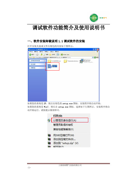
一、软件安装卸载说明 1.1 调试软件的安装
打开安装光盘或文件压缩包的内容如下图所示:
如果您的系统是 XP,则点击绿色的 setup.exe 图标,安装程序将自动开始。 如果您的系统是 Win7,则右击 setup.exe 图标,选择如下左图所示,安装程序将自 动开始运行,请按提示继续即可。
1.4L 1.6L 1.8L 2.0L 2.4L 3.0L 1.8T 2.0T
LPG
1.6 1.8 2.0 2.0 2.2 2.6 2.4 2.6
CNG
2.0 2.0 2.2 2.2 2.4 2.6 2.6 2.8
注释:
- 11 -
上海依相燃气设备有限公司
A:燃油时的喷油脉宽 B:燃气时的喷油脉宽 C:燃气时的喷气脉宽 C=全段比例×B+全段偏移 减压器压力和喷轨孔径按上述设定好后,开始调试,调试的步骤为:
缸序选择:选择正向时,即采集喷油信号一、二、三、四缸后,转化的喷气信号对 应一、二、三、四缸;选择反向时,即采集喷油信号一、二、三、四缸 后,转化的喷气信号对应四、三、二、一缸。
注:此选项请慎重更改,错误更改后有可能导致自动标定时发生非正常熄火,高速 滑行熄火、怠速不稳等情况;
- 10 -
上海依相燃气设备有限公司
第二步 燃气开环调试: 使发动机转速瞬间加到最高转速,加速瞬间听发动机声音是否发闷(正常情
况下是清脆的声音)最高转速是否和燃油一样(可对比燃油同工况下的现象),如果 加速瞬间发动机声音发闷,最高转速低于燃油最高转速,可以尝试把分段偏移的 10ms 以上的区间减小,再次试验看现象有无好转,如果效果不明显,可以尝试降低全段 比例的数值,再次试验,直至上述现象消失;
气脉宽(G.inj)、燃气温度(T.Gas)七个实时数据。 油气脉宽区:显示八个缸的油气脉宽(根据实际缸数而定,无信号则显示 0.0ms) 通讯指示灯:通讯指示灯蓝绿色交替闪烁,表示通讯成功
11款荣威350自动挡说明书

11款荣威350自动挡说明书
1、限制启动。
发动机在启动时,自动变速箱对挡位也做了限制,这是厂家出于安全的考虑而对变速箱所做的调整。
一般只有当变速杆处于挡位P或N的位置,才可以启动发动机。
如果变速杆在行驶挡位,诸如D、R等位置,发动机不能启动。
这一限制的目的是为了防止汽车与前后的物体发生碰撞。
2、换入行驶挡位。
车子启动要走时,只有踏下制动踏板,方可将变速杆从P挡或N挡移出,换入行驶挡位。
松开制动踏板,车子就可以慢慢行驶了。
之所以要提前踩刹车,目的也是为了司机和车子的安全。
3、行驶中自由切换挡位。
在行驶中可以自由地切换前进挡(手动模式和自动模式)。
这些挡位虽然限制可以达到的最高档位,但是只要挡位与速度匹配,就可以自由切换。
4、行驶中不可N档滑行。
因为自动变速箱内需要润滑,当行驶中把档位放在N上面时油泵是无法正常地供油进行润滑的,会使变速箱内部件温度升高,造成彻底损坏!另外高速空档滑行也是非常危险的,而且并不省油。
5、车子停稳后再挂入倒档。
由于自动变速箱内有液压传动机构,且液体流动有一定的惯性,不能猝然就发生变化,所以最好是在车子停稳后,再挂入倒
挡。
车辆未完全停稳前,绝对禁止把变速杆挂入P挡。
停车后,必须熄火挂入P档才能抽出钥匙。
6、行驶中不可推入P挡。
在车辆行驶过程中千万不可推入P档,除非你不想要车了。
需要改变行驶方向时,一定要等车辆停稳后再做切换档位。
英威腾 Goodrive350 用户手册说明书

Goodrive350 系列变频器Auto Station可编程扩展卡安全注意事项安装和操作本扩展卡的工作人员必须经过专业的电气培训和安全知识培训并且考试合格,已经熟悉本扩展卡的安装、调试、投入运行以及维护保养的步骤和要求,并能避免产生各种紧急情况。
在安装、拆除和操作扩展卡前,请仔细阅读本说明书和变频器说明书的安全注意事项章节,确保在安全下操作。
如因用户未遵守本说明书和变频器说明书的安全注意事项而造成的伤害和设备损坏,本公司将不承担责任。
●安装或拆除本扩展卡时需要拆开变频器的机壳,因此必须要完全断开变频器所有的电源输入,并确保设备内部电压已安全,方法请见变频器说明书。
如果不遵守该项要求,可能会造成严重的人身伤害,甚至死亡。
●存放扩展卡时,必须将之放于具防尘、防潮、不受电击以及没有机械压力的地方。
●扩展卡对静电敏感,在相关操作时,必须做好防静电措施,以免损坏元器件。
●在安装本扩展卡时,一定要拧紧螺钉,确保不松动及接地正常。
目录安全注意事项 (i)目录.......................................................................................................................................... i i 第1章产品确认 .. (1)第2章产品概述 (2)2.1 基本介绍 (2)2.2 型号说明 (2)2.3 端子排布说明 (3)2.4 卡状态指示 (5)第3章二次开发平台 (6)3.1 上位机Auto Station开发环境介绍 (6)3.2 PLC程序下载接口说明 (6)3.3 Auto Station编程软件的使用说明 (7)第4章Auto Station编程接口和定义 (11)4.1 Auto Station编程接口导入与导出 (11)4.2 开关量输入和输出编程接口 (13)4.3 模拟量输入和模拟量输出编程接口 (16)4.4 控制命令和功能指令编程接口 (17)4.5 功能参数设定编程接口 (20)4.6 功能参数查看和变频器状态查看接口 (21)4.7 PLC自定义故障(当前设计10个)接口 (24)4.8 写入组编程接口 (25)4.9 监控组编程接口 (25)4.10 RUN/STOP拨码开关及PLC卡运行状态说明 (26)4.11 PLC卡与DP/CANopen/PN通信通道 (27)4.12 485通讯及用户数据掉电存储功能 (32)第5章编程举例说明 (33)5.1 可编程扩展卡开关量输入输出端子应用 (33)5.2 端子控制运行/故障应用 (33)5.3 多段速设定与运行应用 (34)5.4 485通信应用 (36)附录A 可编程扩展卡与变频器交互D元件一览表 (38)附录B 可编程扩展卡功能码组(P27组)一览表 (48)在接收到可编程扩展卡产品时请确认以下内容:●检查可编程扩展卡是否有损坏。
荣威350

2010年4月23日上市在第十一届北京国际车展上,搭载3G智能网络行车系统的“全时在线中级轿车” ——荣威350全球首发上市,并对外公布了5款车型售价。
荣威350是上海汽车自主品牌全新A级车战略平台的首个车型,是国内首款信息化汽车,搭载的智能网络行车系统依托联通WCDMA 3G网络,实现信息检索、实时路况导航、电子路书、股票交易和社群交流等互联应用,开启了汽车的网络互联信息化时代。
中国联通董事长常小兵当日受邀出席,与上汽集团董事长、党委书记胡茂元,以及中外数百位媒体共同见证了新车亮相。
荣威350搭载全新开发、同级领先的 1.5L VTi高效能发动机,匹配4速Multi-Mode自动变速箱和5速SSG手动变速箱,在同级车中率先满足CNCAP 五星级设计标准以及欧IV排放标准,2650mm超长轴距造就最为充足的车内使用空间。
荣威350有5款车型可供选择,分别是:1.5L MT 讯驰版8.97万元,1.5L AT 讯达版10.07万元,1.5L MT讯智版10.27万元,1.5L AT 讯逸版11.47万元,1.5L AT 讯豪版12.47万元,全车系可选配InkaNet智能网络行车系统科技选装包,其各项指标全面超越目前国内A级车的主要竞争对手。
最强性价比荣威350作为上海汽车进入目前市场上容量最大、增速最快的A级车细分市场的战略部署车型,进一步完善了上海汽车自主品牌从B级车、到A+级车和A级车的产品矩阵,价格体系覆盖了9万—26万的主流价格区间。
基于全新平台架构、搭载全新发动机、应用全新互联科技的荣威350,将成为荣威品牌的又一款拳头产品,为上海汽车自主品牌在2010年实现销量翻番、年销量踏上18万辆的新规模,提供强劲的支撑。
国内A级车市场主流车型的发动机为1.6L,价格分布在10万-15万之间,而搭载了1.5L VTi高效能发动机的荣威350,在动力相近的情况下,以最优空间、最佳性能、最丰富配置和8万-12万的价格区间所带来的最高性价比,超越了国内同级产品。
荣威RX5娱乐导航手册

蓝牙电话 ..................................................... 55
使用须知 ..................................................................................................55 蓝牙匹配及连接 ........................................................................................56 电话菜单 ..................................................................................................57 拨号盘 .....................................................................................................58 通讯录 .....................................................................................................59 通话记录 ..................................................................................................60 连接 .........................................................................................................61 拨打电话 ..................................................................................................61 来电 .........................................................................................................65
荣威350整车电路图手册(可编辑)

荣威350整车电路图手册(可编辑)荣威350整车电路图手册目录序言 .................................................................. .. (7)关于这份文件 . 7概要 7参考 7蓄电池电压 . . 7电气防护 . 8概要 8设备 8极性 8高压电路 . . . 8连接器和线束 . 8蓄电池断开 . . 8蓄电池充电 . . 8规则 8缩略语 . . 9概要 9电线颜色代号 . . . 12概要 . . . . 12以下表格是线束颜色代号代表的颜色 12 线束简称 13概要 . . . . 13线束配置代码表 . . 14概要 . . . . 14电源线路功能 . . . 15电源线路功能编号的含义 15电源线路图示 15连接器列表说明 . . 16概要 . . . . 16例表: . . . . 16例图: . . . . 16故障诊断 17概要 . . . . 17如何使用电路图 . . 18导线跨页 . . 18屏蔽线 . . . 18双绞线 . . . 19双绞线在电路图如上图所示。
. . . . 19 部件 . . . . 19导线属性 . . 191V0.1如何使用电路图 20连接器 . . . .20部件端连接器 .20对接连接器 . .20定位图 .................................................................. .. (21)发动机线束 -正面 . . . . 21发动机线束 -背面 . . . . 22自动变速箱线束 23暖风机线束 (自动恒温空调 . . . . 24暖风机线束 (电子控制空调 .25发动机舱线束 . . .26车身线束,前地板 .27车身线束,发动机舱 28车身线束 - 左侧 . .29车身线束 - 右侧 . .30仪表板线束 . . . .31驾驶侧门线束 . . .33副驾驶侧门线束 . .34左后门线束 . . . .35右后门线束 . . . .36尾门线束 37顶蓬线束 38接地点俯瞰图 . . .39保险丝说明 .................................................................. . (40)概要 . .40发动机舱保险丝盒 .41乘客舱保险丝盒 . .44电源分配电路图 ..................................................................46发动机舱电源分配 .46发动机舱电源分配 .47发动机舱电源分配 .48发动机舱电源分配 .49发动机舱电源分配 .50发动机舱电源分配 .51发动机舱电源分配 .52乘客舱电源分配 . .53乘客舱电源分配 . .54乘客舱电源分配 . .55乘客舱电源分配 . .562V0.1目录维修电路图 .................................................................. . (58)1. 起动&充电 58A .连接器信息 59B . 连接器端视图 . . . 602. 发动机管理系统-1.5L(1) 61A .连接器信息 62B . 连接器端视图 . . . 633. 发动机管理系统-1.5L(2) 64A .连接器信息 65B . 连接器端视图 . . . 664. 发动机管理系统-1.5L(3) 67A .连接器信息 68B . 连接器端视图 . . . 695. 发动机管理系统-1.5L(4) 70A .连接器信息 71B . 连接器端视图 . . . 726. 发动机管理系统-1.5L(5) 73A .连接器信息 74B . 连接器端视图 . . . 757. 发动机管理系统-1.5L(6) 76A .连接器信息 77B . 连接器端视图 . . . 788. 冷却风扇 79A .连接器信息 80B . 连接器端视图 . . . 819. 燃油泵&惯性开关 82A .连接器信息 83B . 连接器端视图 . . . 8410. 自动变速箱,TCU 1 85A .连接器信息 86B . 连接器端视图 . . . 8711. 自动变速箱, TCU 2 88A .连接器信息 89B . 连接器端视图 . . . 9012. 自动变速箱, TCU 3 91A .连接器信息 92B . 连接器端视图 . . . 9313. 自动控制空调,ATC 1 94A .连接器信息 95B . 连接器端视图 . . . 96 14,自动控制空调-ATC 2 97A .连接器信息 983V0.1B . 连接器端视图 . . . .99 15,自动控制空调-ATC 3 100 A . 连接器信息 101B . 连接器端视图 . . . 102 16,电子控制空调,ETC 1 103A . 连接器信息 104B . 连接器端视图 . . . 105 17,电子控制空调,ETC 2 106A . 连接器信息 107B . 连接器端视图 . . . 108 18,ABS,DSC和牵引力控制 109A . 连接器信息 110B . 连接器端视图 . . . 111 19,组合仪表 1 112A . 连接器信息 113B . 连接器端视图 . . . 114 20,组合仪表 2 115A . 连接器信息 116B . 连接器端视图 . . . 118 21,组合仪表 3 119A . 连接器信息 120B . 连接器端视图 . . . 12122. 驾驶员座椅 122A . 连接器信息 123B . 连接器端视图 . . . 124 23,后视镜 125A . 连接器信息 126B . 连接器端视图 . . . 127 24,天窗 128A . 连接器信息 129B . 连接器端视图 . . . 130 25,雨刮器和洗涤器 131A . 连接器信息 132B . 连接器端视图 . . . 133 26,内部灯光 134A . 连接器信息 135B . 连接器端视图 . . . 136 27,转向灯&危险警告灯 137A . 连接器信息 138B . 连接器端视图 . . . 140 28,雾灯 141A . 连接器信息 1424V0.1目录B . 连接器端视图 . . . 143 29,制动灯&尾灯 144A .连接器信息 145B . 连接器端视图 . . . 147 30,倒车灯 148A .连接器信息 149B . 连接器端视图 . . . 15031,前照灯-近光 151A .连接器信息 152B . 连接器端视图 . . . 15432,前照灯,远光 155A .连接器信息 156B . 连接器端视图 . . . 15733,前位置灯 158A .连接器信息 159B . 连接器端视图 . . . 16034,车窗升降 1 161驾驶员车窗电机,驾驶员车窗开关 . 161A .连接器信息 162B . 连接器端视图 . . . 16335,车窗升降 2 164A .连接器信息 165B . 连接器端视图 . . . 16736,车窗升降 3 168A .连接器信息 169B . 连接器端视图 . . . 17037,喇叭 171A .连接器信息 172B . 连接器端视图 . . . 17338,车辆安全系统 1 174A .连接器信息 175B . 连接器端视图 . . . 176 39,车辆安全系统 2 177A .连接器信息 178B . 连接器端视图 . . . 180 40,防盗&锁止 1 181A .连接器信息 182B . 连接器端视图 . . . 183 41,防盗&锁止 2 184A .连接器信息 185B . 连接器端视图 . . . 186 42,安全气囊,回路 1875V0.1A . 连接器信息 188B . 连接器端视图 . . . 189 43,安全气囊,回路 1 190A . 连接器信息 191B . 连接器端视图 . . . 192 44,安全气囊,回路 2 193A . 连接器信息 194B . 连接器端视图 . . . 195 45,停车距离控制 PDC 196A . 连接器信息 197B . 连接器端视图 . . . 19846,音响系统,导航 1 199A . 连接器信息 200B . 连接器端视图 . . . 20147,音响系统,导航 2 202A . 连接器信息 203B . 连接器端视图 . . . 20548,音响系统,CD 1 206A . 连接器信息 207B . 连接器端视图 . . . 20849, 音响系统, CD 2 . . 209A . 连接器信息 210B . 连接器端视图 . . . 21250,总线系统和诊断接口 213A . 连接器信息 214B . 连接器端视图 . . . 2166V0.1序言序言关于这份文件概要这份文件旨在帮助您诊断电气故障。
- 1、下载文档前请自行甄别文档内容的完整性,平台不提供额外的编辑、内容补充、找答案等附加服务。
- 2、"仅部分预览"的文档,不可在线预览部分如存在完整性等问题,可反馈申请退款(可完整预览的文档不适用该条件!)。
- 3、如文档侵犯您的权益,请联系客服反馈,我们会尽快为您处理(人工客服工作时间:9:00-18:30)。
自由行导航
用户手册
2013.01.24上海
目 录
1、 如何启动导航? (5)
2、 如何开始导航? (6)
1)选择目的地 (6)
2)选择路径 (8)
3、 如何打开实时路况功能? (10)
4、 为何不能打开实时路况功能? (12)
5、 如何使用实时路况的功能? (14)
1)三条路径的路况对比 (14)
2)航线路况 (15)
3)路况播报 (15)
4)路况查询 (16)
5)省时路径 (17)
6、 如何更快捷的找到目的地? (19)
方法一:搜索类型 (19)
方法二:查找周边 (21)
方法三:我的最爱 (23)
方法四:历史记录 (24)
方法五:在地图上选点 (25)
7、 如何设置参数? (26)
1)实时路况设置 (26)
实时路况功能 (26)
路况更新频率 (26)
省时路径提醒 (26)
我的路况提醒 (27)
路况自动播报 (27)
路况类型选择 (27)
地图路况显示 (28)
2)地图显示设置 (28)
自动比例尺 (28)
日夜模式色设置 (29)
3)高级设置 (29)
4)其他设置 (30)
8、 如何退出? (30)
9、 免责声明 (31)
10、 常见问题列表 (32)
1)如何恢复原来导航 (32)
2)有BUG如何处理及反馈 (32)
3)是否支持实时路况 (32)
11、 联系我们 (33)
1、 如何启动导航?
按面板上【NAV 】键,第一次启动需要5秒左右,会显示“正在加载地图…“
2、 如何开始导航?
1)选择目的地
点击屏幕左下角按钮,弹出【主菜单】界面;
点击搜索地址图标,开始输入目的地,
输入拼音的第一个字母即可,不要输入全部的拼音, 示例:“人民广场”, 输入:“ rmgc ”, 点击
; 或者2秒后,系统会
自动弹出搜索结果。
按 面板按钮 【 返回 】 键, 取消 字母键盘,
2)选择路径
点击箭头 开始计算
选择路线
点击按钮,
路口提示,表示下一个路口,右转弯, 离当前车位 30米。
到达目的地的声音时间和距离
3、 如何打开实时路况功能?
在屏幕右下角中的按钮组合
选择
点击 打开和关闭
4、 为何不能打开实时路况功能?
点击导航快捷键中 ,
进入【实时路况设置】
点击 可以获取当前支持的城市列表:
5、 如何使用实时路况的功能?
1)三条路径的路况对比
在选择一个目的地后,完成路径计算,弹出的选择路线的界面,使用了实时路况。
红色,表示拥堵路段的比例示意;
绿色, 表示通畅路段的比例示意;
黄色, 表示缓行路段的比例示意;
蓝色,表示没有路况的比例示意;
注: 没有使用实时路况, 或者
没有支持实时路况的城市,显示全部是蓝色。
2)航线路况
在开始导航后, 可以显示当前航线上的路况, 如下图
3)路况播报
4)路况查询
5)省时路径
● 在您行驶的道路上, 如果遇到拥堵,系统可能会提示您有新省时路径;
● 1.5 公里,表示车位和新路径开始的距离。
● 32 分钟,表示新路径可以节省的时间。
● 选择 【 是】 开始新路径; 选择 【查看】, 可以查看地图示意路径差别
● 可以通过方向盘按钮上 【 往前】【往后】 进行选择, 通过 【OK】 确认。
●粉红色表示新的路径,一个白色箭头表示两天路径的分离和合并处;
●您可以让系统自动选择新的路径,在 【导航快捷】 【导航设置】中,可以选择手动
或自动。
6、如何更快捷的找到目的地?
方法一:搜索类型(首拼、交叉路况、门址)
【名称】:输入中文关键字或者英文第一个拼音
举例:输入“美罗”可以找到美罗大厦,输入“浦东机场”可以找到“浦东国际机场” 输入拼音第一个字母,
举例:“mlds” 可以找到 美罗大厦,“zsxl” 先找到 中山西路,
【交叉路口】:输入交叉路口的中文名
举例: 中山西路吴中路, 可以输入 “ zsxlwzl ”或者 “中山西路吴中路”
【门址】: 输入门牌号码
举例: “天钥桥路30”, 可以输入 “ tyql30 ”
选择城市按钮:
列表框中选择目的地城市:
【 搜索按钮 】:
在输入关键字或者首字母之后,点击“搜索”按钮即可进行地图搜索。
方法二:查找周边
位置快捷
点击
点击加油站,可以显示周边加油站的方位和距离。
方法三:我的最爱
选择 【位置快捷】中的,
方法四:历史记录
选择【位置快捷】中的 , 选择如下收藏夹:
方法五:在地图上选点(点地图 3秒)
选择 , 可以开始导航。
7、 如何设置参数?
1)实时路况设置
实时路况功能
关闭和打开所有实时路况相关的功能;
不支持路况的城市无法打开这个功能。
路况更新频率
表示路况更新的频率,建议 1分钟,这样路况更准确。
省时路径提醒
在有新的省时路径时,是提示出来,还是自动选择,或者是不计算。
我的路况提醒
可以在【路况快捷】在选择选择自己关注的看板,
在打开以后,每次第一次进入导航时,可以自动显示关注的看板。
路况自动播报
在行驶时,如果有前方有路况变化,拥堵和缓行的时候,语音会自动提示。
路况类型选择
有些城市提供2种路况的类型,请选择其中一种即可。
地图路况显示
在路径引导的时候,把地图上的路况显示隐藏,这样可以更清楚的显示航线路况,有更干净美观的地图显示。
建议关闭。
2)地图显示设置
自动比例尺
表示地图的放大缩小,有软件自动控制,自己设置无效。
日夜模式色设置
建议使用自动切换,日出日落时间根据当地的经纬度季节自动计算切换完成。
3)高级设置
频繁时候,对于不是主路上的匝道,提供语音一次播报
对于桥梁和隧道,进入之前,提示一次语音播报。
可以选择,避开高速、避开收费、避开高架(上海)、避开渡口三种类型;
4)其他设置
8、 如何退出?
选择设置最后一项, 点击“退出”按钮, 可以退出。
9、免责声明
本导航软件是驾驶员行车辅助系统,为驾驶员提供地图与引导信息方面的参考,实际使用中请按照实际路况与当地的交通规则驾驶,注意,在车辆行驶过程中请勿操作本系统。
如因使用本航软件而发生交通事故或其他任何问题,本公司均不承担任何法律责任。
实时路况不能100%的准确,有延迟等不确定的因素,仅供参考。
10、常见问题列表
1)如何恢复原来导航?
通过升级 OS 升级包,把OS烧录恢复即可。
2)有BUG如何处理及反馈?
请拨打终端用户咨询电话反馈,电话:4006701777
3)是否支持实时路况?
实时路况功能目前并没做到覆盖全国,仅支持部分城市。
支持的城市名单如下:
11、联系我们
公司: 上海博泰悦臻网络服务技术有限公司
地址:上海市徐汇区天钥桥路30号 美罗大厦 19楼邮编:200030
终端用户咨询电话:4006701777。