SmartLineSTR700SmartLine远传法兰变送器-霍尼韦尔
霍尼韦尔远传法兰压力差压变送器STR9XX
2
ST3000/900 系列全智能远传法兰压力 / 差压变送器
法兰密封描述
图7-鞍型法兰 可以提供3"和4"(6条螺栓或8条螺栓)的过程连接法 兰,用于差压和压力变送器。
图7
图8-标定环 的冲洗口。
可以用于平法兰和饼式法兰,标定环上有1/4"或者1/2"
图8
图9-不锈钢铠装毛细管和带PVC护套的不锈钢铠装毛细管与 Honeywell远传法兰一起提供。
物理特性和认证机构
密封隔离膜片 密封垫圈材料 安装支架 填充液(表体) 填充液 (毛细管及法兰内) 316L SS,蒙乃尔合金,哈氏合金C-276,钽 Klinger C-4401(非石棉),Grafoil,Teflon,Gylon 3510。 碳钢(镀锌)或不锈钢角支架,或碳钢平板支架 硅油(DC200 ) 25℃时,密度=0.94 CTFE(氟油) 25℃时,密度=1.89 硅油(DC 200) 25℃时,密度=0.94 CTFE(氟油) 25℃时,密度=1.89 硅油(DC 704) 25℃时,密度=1.07 Syltherm 800 25℃时,密度=0.90 NEOBEEM-20 25℃时,密度=0.93 环氧聚酯油漆,低铜铝合金。满足NEMA 4X(防水)和NEMA 7(防爆)要求 不锈钢铠装或带PVC护套的不锈钢铠装。长度:1.5,3,4.5,6,7.5和10.5米。 可选2英寸(50mm)不锈钢硬管 16AWG(1.5mm直径) 变送器:4.1Kg,总重量由法兰类型和毛细管长度决定 具有隔爆和本安认证,可用于Class I,Devision 1,Group A,B,C,D场合,和 非易燃的Class I, Devision 2,Group A,B,C,D场合。ATEX标准的EEx ia IIC T4,T5,T6和EEx d IIC T5,T6认证。详见选型表
smartlinestd800smartline差压变送器规格3st0霍尼韦尔
插入式脉冲线路检测
STD800 型号配有 PILD 选项 ,提供插入式脉冲线路或 过程连接指示 。 配合基本型或高级显示表头使用时 ,非关键 性诊断信息显示在集成表头上 。 对于没有集成显示表头的仪 器, 可以在使用 HART 协议时 , 通过主机或手持设备显示 这些信息 。
100:1
0.010
0.05/0.025%
100:1
0.040
0.05 / 0.0325%
100:1
0.030
0.05 / 0.035%
0
工作条件 –所 有型号
80
D T
参数
S
环境温度 1
STD800
仪表本体温度 2 STD810, 820, 830, 870 STD825
参考条件 ℃
25 ± 1
25 ± 1 25 ± 1
说明
双线, 4 至 20 mA (仅限于 HART 和 DE 变送器 ) 支持霍尼韦尔 、HART 7 协议或基金会现场总线 ITK 6.0.1 所有变送器 ,无论使用何种协议 ,均为无极性连接
37 42.4
15
22.1 27.9 33.6 37.9 42.4
对于 DE, Rl max =35 x ( 电源电压 -15)
对于 HART, Rl max =45.6 x ( 电源电压 -10.8)
0
80
图 2 电源电压以及回路电阻图与计算
D T
S
额定条件下的性能 - 所有型号
参数 模拟输出 数字通信
相关条件 ℃
SmartLine STD700智能差分压力传感器说明书

SmartLineIntroductionPart of the SmartLine® family of products, the STD700 issuitable for monitoring, control and data acquisition featuring piezoresistive sensor technology. By combining pressuresensing with on chip temperature compensation capabilitiesSTD700 offers high accuracy, stability and performance over a wide range of application pressures and temperatures. TheSmartLine family is also fully tested and compliant withExperion® PKS providing the highest level of compatibilityassurance and integration capabilities. SmartLine easily meets the most demanding application needs for pressuremeasurement applications.Best in Class Features:•Accuracies up to 0.05% of span standard & 0.04% of span optional.•Stability up to 0.02% of URL per year for 10 years. •Automatic static pressure & temperature compensation. •Rangeability up to 100:1.•Response times as fast as 100ms.•Multiple local display capabilities.•External zero, span, & configuration capability. •Polarity insensitive electrical connections. •Comprehensive on-board diagnostic capabilities. •Integral Dual Seal design for highest safety based on ANSI/NFPA 70-202 and ANSI/ISA 12.27.0.•World class overpressure protection.•Full compliance to SIL 2/3 requirements.•Modular design characteristics•Available with additional 4-year warranty Communications/Output Options:•Honeywell Digitally Enhanced (DE)•HART ® (version 7.0)All transmitters are available with the above listed communications protocols. Figure 1 – STD700 Differential Pressure Transmitters feature field-proven piezoresistive sensor technologyDescriptionThe SmartLine family pressure transmitters are designed around a high performance piezo-resistive sensor. This one sensor actually integrates multiple sensors linking process pressure measurement with on-board static pressure (DP Models) and temperature compensation measurements. This level of performance allows the ST 700 to replace most competitive transmitters available today.Unique Indication/Display OptionThe ST 700 modular design accommodates a standard alphanumeric LCD display or a unique advanced graphics LCD display with many unparalleled features.Standard LCD Display Features•Modular (may be added or removed in the field).•Supports HART protocol variant.•0, 90,180, & 270 degree position adjustments.•Four configurable screens.•Standard and custom measurement units available. •Display calculated flow (square root) value in addition to analog output signal.• 2 Lines 6 digits PV (9.95H x 4.20W mm) 8 Characters. •Write protect Indication.•Built-in Basic Device Configuration through Internal or External Buttons – Range/Engineering Unit/Loop Test/Loop Calibration/Zero /Span Setting.•Multiple language capabilities (EN, RU).Advanced LCD Display Features•Modular (may be added or removed in the field)•0, 90,180, & 270 degree position adjustments. •Standard and custom measurement units available. •Up to eight display screens with 3 formats are possible. •Large PV with Bar Graph or PV with Trend Graph. •Configurable screen rotation timing (1 to 30 sec). •Display calculated flow (square root) value in addition to analog output signal.•Unique “Health Watch” indication provides instant visibility of diagnostics.•Multiple language capability (EN, DE, FR, IT, ES, RU, TR, CN, & JP).DiagnosticsSmartLine transmitters all offer digitally accessible diagnostics which aid in providing advanced warning of possible failure events minimizing unplanned shutdowns, providing lower overall operational costs. System Integration•SmartLine communications protocols all meet the most current published standards for HART/DE. •Integration with Honeywell’s Experion PKS offers the following unique advantages.o Tamper reportingo FDM Plant Area Views with Health summarieso All ST 700 units are Experion tested to provide the highest level of compatibility assurance. Configuration ToolsIntegral Three Button Configuration OptionSuitable for all electrical and environmental requirements, SmartLine offer the ability to configure the transmitter and display via three externally accessible buttons when either display option is selected. Zero/span capabilities are also optionally available via these buttons with or without selection of a display option.Handheld ConfigurationSmartLine transmitters feature two-way communication and configuration capability between the operator and the transmitter. All Honeywell transmitters are designed and tested for compliance with the offered communication protocols and are designed to operate with any standards compliant handheld configuration device, such as Honeywell Versatilis Configurator.Personal Computer ConfigurationOn a personal computer or laptop, Honeywell Field Device Manager (FDM) Software and FDM Express can be used for managing HART device configurations.Modular DesignTo help contain maintenance & inventory costs, all ST 700 transmitters are modular in design supporting the user’s ability to replace meter bodies, add indicators or change electronic modules without affecting overall performance or approval body certifications. Each meter body is uniquely characterized to provide in-tolerance performance over a wide range of application variations in temperature and pressure and due to the Honeywell advanced interface, electronic modules may be swapped with any electronics module without losing in-tolerance performance characteristics.Modular Features•Meter body replacement•Exchange/replace electronics/comms modules*•Add or remove integral indicator*•Add or remove lightning protection (terminal connection)** Field replaceable in all electrical environments (including IS) except flameproof without violating agency approvals.With no performance effects, Honeywell’s unique modularity results in lower inventory needs and lower overall operating costs.Performance SpecificationsReference Accuracy (conformance to +/-3 Sigma)Zero and span may be set anywhere within the listed (URL/LRL) range limitsAccuracy at Specified Span, Temperature and Static Pressure Effects: (conformance to +/-3)Total Performance (% of Span):Total Performance = +/-√(Accuracy)2 + (Temp Effect)2+ (Static Line Pressure Effect)2Total Performance Examples (for comparison): standard accuracy, 5:1 Turndown, up to 50o F (28o C) shift & up to 1000 psi Static PressureSTD720 @ 80 inH2O: 0.218% of spanSTD730 @ 20 psi: 0.199 % of spanSTD770 @ 600 psi: 0.196 % of spanTypical Calibration Frequency:Calibration verification is recommended every two (2) years.Notes:1. Terminal Based Accuracy – Includes combined effects of linearity, hysteresis and repeatability. Analog output adds 0.005% of span.2.For zero based spans and reference conditions of: 25o C (77o F), 0 psig static pressure, 10 to 55% RH and 316SS barrier diaphragm.Operating Conditions – All Models1 LCD Display operating temperature -20︒C to +70︒C. Storage temperature -30︒C to 80︒C.2Silicone 704 minimum temperature rating is 0o C (32o F). CTFE minimum temperature rating is -40︒C (-40︒F).NEOBEE ® M-20 minimum temperature rating is -15o C (5o F). NEOBEE ® is a registered trademark of Stepan Company.3 Short term equals 2 hours at 70︒C (158︒F).4MAWP applies for temperatures -40 to 125︒C. Static Pressure Limit is de-rated to 3,000 psi for -26︒C to -40︒C. for all models. Use of graphite o-rings de-rates transmitter to 3,625 psi. Use of 1/2:” process adaptors with graphite o -rings de-rates transmitter to 3,000 psi. 5Consult factory for MAWP of ST 700 transmitters with CRN approval.Figure 2 - Supply voltage and loop resistance chart & calculationsPerformance Under Rated Conditions – All ModelsMaterials Specifications (see model selection guide for availability/restrictions with various models)3 Monel 400 or UNS N044004 Supplied as 316 SS or as Grade CF8M, the casting equivalent of 316 SS.5 Carbon Steel heads are zinc-plated and not recommended for water service due to hydrogen migration. For that service, use 316 stainless steel wetted Process Heads.6 Hastelloy C-276 or UNS N10276. Supplied as indicated or as Grade CW12MW, the casting equivalent of Hastelloy C-276Communications Protocols & DiagnosticsHART ProtocolVersion: HART 7Honeywell Digitally Enhanced (DE)DE is a Honeywell proprietary protocol which provides digital communications between Honeywell DE enabled field devices and hosts.Standard DiagnosticsST 700 top level diagnostics are reported as either critical or non-critical and are readable via the DD/DTM/FDI tools or integral display. All critical diagnostics will appear on the Advanced and Standard integral displays, and some non-critical diagnostics will also appear on the Advanced integral display. Some of the diagnostics are listed below.Critical Diagnostics•Electronics Module Fault.•Meter body Memory Corruption.•Config Data Corruption.•Electronics Module Diagnostics Failure.•Meter body Critical Failure.•Sensor Communication Timeout.Non-Critical Diagnostics•Electronics Module Fault.•Display Failure.•Electronics Module Comm Failure.•Meter body Excess Correct.•Sensor Over Temperature.•Fixed Current Mode.•PV Out of Range.•No DAC Compensation.•Tamper Attempt Alarm.Refer to the product user manual for comprehensive list of diagnostics and details.Hazardous Areal CertificationsII 1/2 G Ex db IIC T6..T5 Ga/Gb II 2 D Ex tb IIIC T95 Intrinsically Safe: SIRA 12ATEX2233XII 1 G Ex ia IIC T4 GaII 2 D Ex ia IIIC T125FISCO Field Device (Only for FF Option)II 3 G Ex ec IIC T4 GcZone 2, Intrinsically Safe: SIRA12ATEX4234XII 3 G Ex ic IIC T4 GcFISCO Field Device (Only for FF Option) II 3 G Ex ic IIC T4 GcFlameproof: CSAE 22UKEX1021XII 1/2 G Ex db IIC T6..T5 Ga/Gb II 2 D Ex tb IIIC T95 Intrinsically Safe: CSAE 22UKEX1021XII 1 G Ex ia IIC T4 GaII 2 D Ex ia IIIC T125FISCO Field Device (Only for FF Option)II 3 G Ex ec IIC T4 GcZone 2, Intrinsically Safe: CSAE22UKEX1009XII 3 G Ex ic IIC T4 GcFISCO Field Device (Only for FF Option) II 3 G Ex ic IIC T4 GcNotes:1. Operating Parameters:Voltage = 11 to 42 VDC = 9 to 32 V (FF) Current = 4-20 mA Normal = 30 mA (FF)2. Intrinsically Safe Entity Parametersa. Analog/ DE/ HART Entity Values:Vmax = Ui = 30V Imax = Ii = 105mA Ci = 4.2nF Li = 984 uH Pi = 0.9WTransmitter with Terminal Block Revision E or LaterVmax = Ui = 30V Imax = Ii = 225mA Ci = 4.2nF Li = 0 Pi = 0.9WNote: Transmitter with Terminal Block Revision E or laterThe revision is on the label that is on the module. There will be two lines of text on the label:•First is the Module Part #: 50049839-001 or 50049839-002•Second line has the supplier information, along with the REVISION:XXXXXXX-EXXXX, THE “X” is production related, THE POSITION of the “E” IS THE REVISION.b. Foundation Fieldbus Entity ValuesVmax = Ui = 30V Imax= Ii = 180mA Ci = 0nF Li = 984 uH Pi = 1WTransmitter with Terminal Block Revision F or LaterVmax = Ui = 30V Imax = Ii = 225mA Ci = 0nF Li = 0 Pi = 1 WFISCO Field DeviceVmax = Ui = 17.5V Imax = Ii = 380 mA Ci = 0nF Li = 0 Pi = 5.32 WNote: Transmitter with Terminal Block Revision F or laterThe revision is on the label that is on the module. There will be two lines of text on the label:•First is the Module Part #: 50049839-003 or 50049839-004•Second line has the supplier information, along with the REVISION:XXXXXXX-EXXXX, THE “X” is production related, THE POSITION of the “E” IS THE REVISION.Approval CertificationsOther Certification OptionsMaterialsNACE MRO175, MRO103, ISO15156Mounting & Dimensional DrawingsReference Dimensions:millimetersinchesMounting ConfigurationsFigure 3 – Typical mounting configurations of STD720, STD730 & STD770 for reference onlyDimensionsFigure 4 – Typical mounting dimensions of STD720, STD730 & STD770 for reference onlyModel Selection GuideModel Selection Guides are subject to change and are inserted into the specifications as guidance only.Model STD700Differential Pressure TransmitterModel Selection Guide:34-ST-16-101, Issue 35Price equals the s um of prices for all selections made.123STD770STD730o STD720Left side/Right side as viewed from the customer connection perspective3NAMUR Output Limits 3.8 - 20.5mAdc can be configured by the customer or select custom configuration Table VcSTD770STD730STD720The PM option is available on all Smartline Pressure Transmitter process wetted parts such as process heads, flanges, bushings and vent plugs except plated carbon steel process heads and flanges. PM option information is also available on diaphragms except STG and STA in-line construction pressure transmitters.For more informationTo learn more about SmartLine PressureTransmitters visit Or contact your Honeywell Account ManagerProcess Solutions Honeywell1250 W Sam Houston Pkwy S Houston, TX 77042Honeywell Control Systems LtdHoneywell House, Skimped Hill Lane Bracknell, England, RG12 1EB34-ST-03-101 October 2023©2023 Honeywell International Inc.Shanghai City Centre, 100 Jungi Road Shanghai, China 20061Sales and ServiceFor application assistance, current specifications, ordering, pricing, and name of the nearest Authorized Distributor, contact one of the offices below.ASIA PACIFICHoneywell Process Solutions, Phone: + 800 12026455 or +44 (0) 1202645583 (TAC) hfs-tac-*********************AustraliaHoneywell LimitedPhone: +(61) 7-3846 1255 FAX: +(61) 7-3840 6481 Toll Free 1300-36-39-36 Toll Free Fax: 1300-36-04-70China – PRC - Shanghai Honeywell China Inc.Phone: (86-21) 5257-4568 Fax: (86-21) 6237-2826SingaporeHoneywell Pte Ltd.Phone: +(65) 6580 3278 Fax: +(65) 6445-3033South KoreaHoneywell Korea Co Ltd Phone: +(822) 799 6114 Fax: +(822) 792 9015EMEAHoneywell Process Solutions, Phone: + 800 12026455 or +44 (0) 1202645583Email: (Sales)*************************** or (TAC)*****************************WebKnowledge Base search engine http://bit.ly/2N5VldiAMERICASHoneywell Process Solutions, Phone: (TAC) (800) 423-9883 or (215) 641-3610(Sales) 1-800-343-0228Email: (Sales)*************************** or (TAC)*****************************WebKnowledge Base search engine http://bit.ly/2N5VldiSpecifications are subject to change without notice.。
Honeywell SmartLine压力传感器选择指南说明书

I Connected IndustriaISMARTLINE PRESSURE SELECTION GUIDELINESRedefining Smart.SmartLine Pressure TransmittersHoneywell’s SmartLine® pressure measurement system sets the standard with its industry-leading total performance, even in harsh process environments. With the best control system integration and unique features such as modularity, a graphics display and universal terminals, SmartLine offers the lowest total cost of ownership.Leading PerformanceSmartLine provides better performance with industry leading accuracy, response time and stability. When combined with Honeywell’s proven static pressure and temperature compensation, the unbeatable total performance is better than 0.12% of span under actual process conditions.Lowest Total Cost of Ownership• H oneywell’s unique approach to modularity helps reduce maintenance costs and make repairs safer and faster. With the ability to repair the transmitter in place, the need to break a process line connection is avoided, even in an intrinsically safe environment. And with no need to stock complete units, inventory costs are lower.• A n advanced graphics display and three button external configuration option provide capabilities for field operators to more efficiently perform tasks,solve problems and avoid errors with no need for a handheld device. The display shows rich graphics, bar graphs, trends and messages from the control room.• W ith SmartLine’s universal terminals, wiring can be reversed without damaging or affecting the normal operation of the transmitter. This avoids costly rework on large installations where multiple contractors may use different wiring standards and eliminates return trips to re-wire “incorrectly wired” devices.SmartLine Connection Advantage• T ransmitter Messaging allows the operator to send and display custom messages to the display so field operators can quickly identify the right transmitter and task.•M aintenance Mode Indication displays a message on the display that the transmitter and/or the loop is in a mode suitable for maintenance. • U nique Tamper Reporting notifies the control room that an attempt to change a write-protected configuration has been made or that the write protection has been switched off.•F ield Device Manager (FDM) is Honeywell’s centralized asset management system for smart field device configuration and maintenance. When SmartLine data is integrated into FDM, users can create hierarchical screen displays for quick and easy views of device health from areas of the plant or process.• W ith comprehensive testing, Honeywell provides trouble-free integration for faster startups and reliability. The tests even include other suppliers’ configuration tools.ST800ST700SMV800 Performance CharacteristicsAccuracy • U p to 0.0375% span standard• 0.025% span optional highaccuracy • B asic: up to 0.065% of span• S tandard: up to 0.05% of span•P V1 DP – up to 0.04% of span• P V2 SP – up to 0.0375% of span• P V3 PT – 0.2 °C RTD – Pt 100• P V4 – mass flow accuracyup to 0.6%Stability• U p to 0.01% per year for ten years• B asic: up to 0.025% per year for5 years• S tandard: up to 0.02% per yearfor 5 years• U p to 0.0625% of URL per yearResponse Time• A s fast as 80 ms• A s fast as 100 ms•A s fast as 144 ms for DP (PV1) Total Performance• U p to 0.12%• U p to 0.2%• M ass flow performance is up to 0.6% Turndown Ratios up to 400:1• T urndown ratios up to 400:1• T urndown ratios up to 100:1• T urndown ratios up to 400:1 Compound Characterized Ranges• Y es• Y es• Y esTemperature & Static PressureCompensated• Y es• Y es• Y esProduct Features & OptionsMeasured Parameters• D ifferential pressure staticpressure • D ifferential pressure staticpressure• D ifferential pressure, staticpressure, process temperatureCaluclated Parameters• V olume flow• V olume flow• V olume flow, mass flow Support for Flow Algorithms• N A• N A• A SME MFC-3M, ISO5167, Gost8.586, AGA3, ASME MFC 14MSupport for Flow Elements• N A• N A• O rifice, Venturi, Flow Nozzle,Pitotube, IFO, Standard V cone,Wafer cone, WedgeHART® 7, DE & F OUNDATION™Fieldbus Communication Protocols• Y es• Y es• D E, HART 7Universal Terminals• Y es• S tandard: Yes• Y esModular Design Components• S imple faster repairs with lessdowntime • S imple faster repairs withless downtime• S imple faster repairs withless downtimeSmartLine Connection Advantage with Experion®• T ransmitter Messaging*• M aintenance Mode Indication• T amper Alerts*• F DM Plant Area Views• C omprehensive Experionintegration testing• T amper Alerts* (Standard only)• F DM Plant Area Views• T ransmitter Messaging*• M aintenance Mode Indication• T amper Alerts*• F DM Plant Area Views• C omprehensive Experionintegration testingSIL 2 Certified/SIL 3Capable Standard• Y es• Y es• N o Certified for Dual Seal Compliance• Y es• Y es• Y esComprehensive & AdvancedDiagnostics• Y es• Y es• Y esUser Interface Options• O ptional basic alphanumeric display• O ptional advanced graphics display• M ultiple PV display screens includingbar graph and trend displays• C omprehensive diagnostic messages• S upports transmitter messagingand maintenance mode indication• C omprehensive EDDs & DTMsfor remote configuration• O ptional external 3-buttonprogramming capability • S T700 Basic: supports Standarddisplay with internal and/orexternal 2-button configurationST700 Standard: supportsStandard display with internal2-button configuration / Basicdisplay with external three buttonconfiguration• Diagnostic notifications•C omprehensive EDDs & DTMsfor remote configuration• O ptional external two (Basic)or three (Standard) buttonprograming capability• N A•O ptional advanced graphics display• M ultiple PV display screens includingbar graph and trend displays• C omprehensive diagnostic messages• S upports transmitter messagingand maintenance mode indication• C omprehensive EDDs & DTMs forremote configuration• O ptional external 3-buttonlimited programming capOptional Extended Warranties• 1, 2, 3, 4 and 15 year warranties• 1, 2, 3 and 4 year warranties• 1, 2, 3, 4 and 15 year warranties *Also compatible with other HART 7 enabled hostsStandard, basic or advanced digital display as determined by the application requirementsUniversal or traditional wiring terminal boards with standard or lightning-protected optionsIt takes only a matter of minutes to replace the electronics, even in the field under power with no re-calibration required. This avoids the time-consuming procedure of removing a sensor from a pipeline or network, particularly in highly critical processes.Best of all, Honeywell’s unique modularity reduces inventory requirements and lowers overall operating costs.LOWER YOUR TOTAL COST OF OWNERSHIPWith Plug-In Modules, Users Can Easily Add or UpgradeAll SmartLine Pressure Transmitters are modular in design, making it easy to replace hardware, add indicators, change electronic modules or even meter bodies without affecting overall performance or impinging on approval body certifications.Flexible ConfigurationIn addition to configuring with any hand-helddevice or through asset management DTMs, users can configure the transmitters through externally accessible buttons, even in an intrinsically safe, Class I, Div. 1 environment.Now, whether on the bench or in the field, configure, change tag information, change languages and even more without needing a handheld device.SMARTLINE PRESSURE SELECTION GUIDEModel Types, Ranges and SpansModelUpper Range Lower Range Max. SpanUnitsStandard Accuracy % of Span Turndown CapabilityTwo- or three-button external configurationField-exchangeable communication modules to deploy HART , Honeywell Digital Enhanced (DE) or FOUNDATION Fieldbus communicationAdvanced Graphics LCD Display• U p to eight separate screens with three formats to meet unique display requirements: process variable, bar graph and trend• F ull library of engineering units with the ability to add custom units• Configurable screen rotation timing • Supports multiple languages • Two diagnostic indications• 90-degree position adjustments to facilitate all installation positions.For more informationTo learn more about Honeywell’s SmartLine Pressure Transmitters, visit /smartlineor contact your Honeywell account manager. Honeywell Process Solutions512 Virginia DriveFort Washington, PA 19034 USAHoneywell House, Arlington Business Park Bracknell, Berkshire, England RG12 1EB17 Changi Business Park Central 1 Singapore 486073 SmartLine® and Experion® are registered trademarks of Honeywell International Inc. HART® is a registered trademark andF OUNDATION™ Fieldbus is a trademark of the FieldComm Group.PO-16-01-ENG | 11/16©2016 Honeywell International Inc.。
SmartLine压力变送器快速安装指引-HoneywellProcess
小绝压或微差压变送器的水平位置调整 ...................................................................... 8
法兰变送器的安装 ......................................................................................................... 9 插入式安装....................................................................................................................10 远传压力变送器的安装 ................................................................................................11 电缆接口盲塞和电缆转接头 ................................................................................................12 接线和上电 ...........................................................................................................................14 接线的变化....................................................................................................................15 防爆电缆接口的密封 ............................................................................................................ 16 变送器校准 ...........................................................................................................................17 变送器校准的步骤 ........................................................................................................17 为 HART/DE 变送器设置跳线 .............................................................................................18 设置失效保险和写保护跳线 .........................................................................................18 基金会现场总线 (FF)型变送器上的写保护跳线 ................................................................20 组态指南 ............................................................................................................................... 21
【精选】霍尼韦尔温度变送器

Galvanic Isolation: Approvals:
Integral Meters
No
FM, CSA, ATEX
EU Meter
Yes
FM, CSA, ATEX
EU Meter
Yes
FM, CSA, ATEX
EU Meter
Yes
FM, CSA, ATEX
温度变送器 防雷保护
装置现场比较典型的浪涌电压 通常在15到600微秒到达峰值800伏 在40到3000微秒后衰减到峰值的一半
Zone 1 approvals. 6. 完全支持所有 HART 5.X 指令 和 HART 6.X 通用指令,以及利用 DD-
IDE/SDC 625 技术的所有“开放”的技术标准。
温度变送器
谢谢
温度变送器 STT170温度变送器
Model Protocol : Configuration Tools:
Inputs:
Pt100 Accuracy T/C Type J Accuracy
STT171 4-20mA STT17C
STT173 4-20mA STT17C
RTD 2 & 3 wire
一旦某一路的温度发生变化, 使2路温度产生温差并达到了预先组态好的温差值, 变送器就会发出报警信号。
温度变送器 STT250智能温度变送器
壁式安装
2寸短管安装
导轨安装
温度变送器 STT250智能温度变送器 SIL 2/3 认证
温度变送器 STT250智能温度变送器 SIL 2/3 认证
温度变送器 STT250智能温度变送器
Model Protocol: Configuration Tools: Inputs: Pt100 Accuracy T/C Type J Accuracy CJ Accuracy Advanced Features:
Honeywell SmartLine STT170系列温度传输器说明书
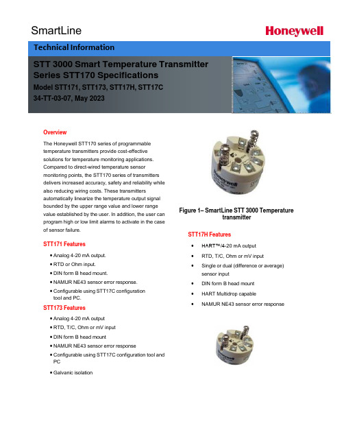
SmartLineOverviewThe Honeywell STT170 series of programmabletemperature transmitters provide cost-effectivesolutions for temperature monitoring applications.Compared to direct-wired temperature sensormonitoring points, the STT170 series of transmittersdelivers increased accuracy, safety and reliability while also reducing wiring costs. These transmittersautomatically linearize the temperature output signalbounded by the upper range value and lower range value established by the user. In addition, the user can program high or low limit alarms to activate in the case of sensor failure.STT171 Features• Analog 4-20 mA output.• RTD or Ohm input.• DIN form B head mount.• NAMUR NE43 sensor error response.• Configurable using STT17C configurationtool and PC.STT173 Features• Analog 4-20 mA output• RTD, T/C, Ohm or mV input• DIN form B head mount• NAMUR NE43 sensor error response• Configurable using STT17C configuration tool and PC• Galvanic isolation Figure 1– SmartLine STT 3000 TemperaturetransmitterSTT17H Features•HART™/4-20 mA output•RTD, T/C, Ohm or mV input•Single or dual (difference or average)sensor input•DIN form B head mount•HART Multidrop capable•NAMUR NE43 sensor error responseSTT 3000 Smart Temperature Transmitter Series STT170 SpecificationsModel STT171, STT173, STT17H, STT17C34-TT-03-07, May 2023Technical InformationDimensions (all models)WiringSTT171 STT173Input:Input:RTD, 2-wire RTD, 3-wire RTD, 4-wire TC, internal CJCRTD,2-wire RTD,3-wire Resistance,2-wire Resistance,3-wireTC, external CJC mV Resistance, 2-wire Resistance, 3-wireOutput:2-wire installationResistance, 4-wireOutput:2-wire installationSTT17HThe STT17C configures the STT171, STT173 and STT17H. The intuitive graphical user interface of the STT17C virtually eliminates the need for operator training after installation on a PC. The STT17C includes all software and transmitter interface hardware necessary to configure the STT171, STT173 and STT17H in non-hazardous work environments.WARNING: The STT17C is not approved for use in Hazardous work environments.System Requirements:Windows® 98SE, ME, 2000 and XP with the following recommendations:Memory: 16 MBDisplay resolution: 800 x 600Hard disk space: 12 MB**or 50%of upper range value,whichever is greater***reference temperature24o COPERATING CONDITIONS APPROVALSAmbient temperature, rated……….……-40 to 85o C (-40 to 185o F)Observed Authority requirements:Standard: Humidity……………………………………0 to 95% RH (non-cond.)EMC 2004/108/EC Vibration…………………………………Max 4g over 25 to 100Hz Emmission and immunity ……… EN 61326ATEX94/9/EC…........................................ EN50014,EN50020, ELECTRICAL INPUT SPECIFICATIONS EN502811-1and EN50284 Supply voltage………………………………8to30VDC FM,ASCN…............................................. 3600,3611,3610Power supply voltage effect………………≤0.005%of span per VDC CSA,CAN/CSA ......................................... C22.2No.157,E60079-11, Warm-up time…………………………..….5min UL913Response time(programmable)…………0.33to60sec Ex/I.S.approval:KEMA06ATEX0042X…………………………II1GD,T80o C…T105o C CURRENT OUTPUT SPECIFICATIONS EEx ia IIC T4.T6Signal output range…………………………4to20mA Max.amb.Temperature for T4….................... 85o CUpdate time………………………………… 135msec Max.amb.Temperature for T6….................... 60o CLoad resistance………....……...…………≤(V supply-8)/0.023A Applicable in zone…..................................... 0,1,2,20,21or220to870οFM,applicable in…………………………………IS,CL I,DIV1,Grp.A-D,T4…T6AEx ia IICALARM LEVELS NI,CL I,DIV2,Grp.A-D,T4...T6 Programmable...................................3.5to4mA downscale Entity,FM Installation Drawing No. (50016324)20 to 23 mA upscale CSA, applicable in.....................................IS,CL I, DIV 1, Grp. A-D, T4...T6 NAMUR NE43 Upscale.........................23 mA Ex ia IIC, AEx ia IIC NAMUR NE43Downscale....................3.5mA Entity,Installation Drawing No... (50016326)Ex/I.S.data:U i (max) .................................................... 30 VDCI i (max)...................................................... 120mADCP i (max) .................................................... 0.84WL i (max)..................................................... 10μHC i (max) .................................................... 1.0 nFUo (max) .................................................. 27 VDCIo (max).................................................... 7 mADCPo (max)................................................... 45m WLo(max) ................................................... 35 mHCo (max) .................................................. 90 nFSTT17H-BN Specification*whichever is greater; Total Reference Accuracy = Basic Accuracy + CJ Accuracy (T/C only)**or 50% of upper range value, whichever is greater*** reference temperature 24o COPERATING CONDITIONS APPROVALSAmbient temperature, rated…………...…. -40 to 85o C (-40 to 185o F) Observed Authority requirements: Standard: Humidity……………………………………0 to 95% RH (non-cond.) EMC 2004/108/EC Vibration…………………………………...…Max 4g over 25 to 100Hz Emmission and immunity ……… EN 61326Cold junction accuracy……………………±1.0o C ATEX94/9/EC… .................................................. EN60079-0,EN60079-15 ELECTRICAL INPUT SPECIFICATIONS Ex / I.S. approval:Supply Voltage....................................8 to 35 VDC KEMA 06 ATEX 0043 X..............................II 3 GD, T80o C...T105o C Power supply voltage effect.................. ≤ 0.005% of span per VDC EEx nA [L] IIC T4. T6 Warm-up time....................................30sec Applicable in zone... (2)Response time(programmable)…………1to60sec Max.amb.Temperature for T4…......................... 85o CGalvanic isolation………………………….1500VAC Max.amb.Temperature for T6…......................... 60o CCURRENT OUTPUT SPECIFICATIONS Vmax (V)Signal output range..................................... 4 to 20 mAUpdate time… ............................................. 440 msecLoad resistance(ν)...................................... ≤(V supply -8)/0.023A0 to 1174 νALARM LEVELSProgrammable…........................................ 3.5 to 4 mA downscale20 to 23 mA upscaleNAMUR NE43 Upscale…......................... 23 mANAMUR NE43Downscale…....................... 3.5 mA9STT 3000 Smart Temperature Transmitter STT171 Custom Configuration Data SheetCustomer P.O. NumberLine ItemModel NumberTag Number (max 15 char)Honeywell Sales Order NumberSensor Type:□Pt100□Ni100□OhmsOutput Values:4 mA Value: 20 mA Value: Response time:□o C□o F□Ohms □o C□o F□Ohms(0.33 – 60 sec)Output Limits:□Span (4 to 20 mA)□Max (3.5 to 23 mA)□Specify Low mA, High mA□NAMUR NE 43 (3.8 to 20.5 mA)Sensor Error Action:□Off□Specify mA□NAMUR NE 43 upscale (23 mA)□NAMUR NE 43 downscale (3.5 mA)10STT 3000 Smart Temperature TransmitterSTT173 Custom Configuration Data SheetCustomer P.O. NumberLine ItemModel NumberTag Number (max 15 char)Honeywell Sales Order NumberSensor Type:□Pt100 □Type B T/C Cold Junction Compensation:□Ni100 □Type E T/C □Internal□Type J T/C □External / Pt100Wiring: □Type K T/C □External / Ni100□2-wire □Type L T/C□3-wire □Type N T/C□4-wire □Type R T/C□Type S T/C□ Ohms □Type T T/C□mV □Type U T/C□Type W3 T/C□Type W5 T/COutput Values:4 mA Value: 20 mA Value: Response time:□o C □o C (1 – 60 sec)□o F □o□mV □mV□Ohms □OhmsOutput Limits:□Span (4 to 20 mA)□Max (3.5 to 23 mA)□Specify Low mA, High mA□NAMUR NE 43 (3.8 to 20.5 mA)Sensor Error Action:□Off□Specify mA□NAMUR NE 43 upscale (23 mA)□NAMUR NE 43 downscale (3.5 mA)STT17H Custom Configuration Data SheetCustomer P.O. NumberLine ItemModel NumberTag Number (max 15 char)Honeywell Sales Order NumberSensor Input:□Single Sensor□Duplex Sensor (Average)□Duplex Sensor (Differential)Sensor Type:□Pt100□Type B T/C Cold Junction Compensation:□Ni100□Type E T/C□Internal□Type J T/C□External / Pt100 Wiring: □Type K T/C□External / Ni100□2-wire□Type L T/C□3-wire□Type N T/C□4-wire□Type R T/C□Type S T/C□Ohms□Type T T/C□mV□Type U T/C□Type W3 T/C□Type W5 T/COutput Values:4 mA Value: 20 mA Value: Response time:□o C□o F□mV □Ohms □o C□o□mV□Ohms(1 – 60 sec)Output Limits:□Span (4 to 20 mA)□Max (3.5 to 23 mA)□Specify Low mA, High mA□NAMUR NE 43 (3.8 to 20.5 mA)Sensor Error Action:□Off□Specify mA□NAMUR NE 43 upscale (23 mA)□NAMUR NE 43 downscale (3.5 mA)Model Selection Guide (34-44-16-07)Model Selection Guides are subject to change and are inserted into the specifications as guidance only.Sales and ServiceFor application assistance, current specifications, pricing, or name of the nearest Authorized Distributor, contact one of the offices below.ASIA PACIFICHoneywell Process Solutions, (TAC) hfs-tac-********************* AustraliaHoneywell LimitedPhone: +(61) 7-3846 1255FAX: +(61) 7-3840 6481Toll Free 1300-36-39-36Toll Free Fax:1300-36-04-70China – PRC - Shanghai Honeywell China Inc.Phone: (86-21) 5257-4568Fax: (86-21) 6237-2826 SingaporeHoneywell Pte Ltd.Phone: +(65) 6580 3278Fax: +(65) 6445-3033South KoreaHoneywell Korea Co LtdPhone: +(822) 799 6114Fax: +(822) 792 9015 EMEAHoneywell Process Solutions,Phone: + 80012026455 or+44 (0)1344 656000Email: (Sales)***************************or(TAC)*****************************AMERICA’SHoneywell Process Solutions,Phone: (TAC) 1-800-423-9883 or215/641-3610(Sales) 1-800-343-0228Email: (Sales)***************************or(TAC)*****************************For more informationTo learn more about Temperature Transmitters,visit Or contact your Honeywell Account ManagerProcess SolutionsHoneywell1250 W Sam Houston Pkwy S Houston, TX 77042Honeywell Control Systems Ltd Honeywell House, Skimped Hill Lane Bracknell, England, RG12 1EB Shanghai City Centre, 100 Jungi Road Shanghai, China 20061 34-TT-03-07May 2023©2023 Honeywell International Inc.。
SmartLineSTR700SmartLine远传法兰变送器-霍尼韦尔

SmartLine简介作为SmartLine ®产品系列的成员,STR700是一款高性能的远传法兰变送器。
通过远传法兰和毛细管内的充油,实现压力的传递和优化。
霍尼韦尔采用SmartLine 高性能传感技术,优化了机械和液压设计,从而大幅度降低了温度对远传法兰测量的常见影响。
同类最佳的特性:● 校验量程的精度高达0.075%● 自动静压和温度补偿● 高达100:1的量程比● 易于使用和直观的显示功能● 外部零位、量程和组态功能● 完善的自诊断功能●基于ANSI/NFPA 70-202和ANSI/ISA 12.27.0集成双重密封设计,可确保最高安全性● 世界一流的过压保护●标准配置完全符合SIL2/3要求量程和范围限制:图1 STR700远传法兰变送器典型应用:●高温(最高达338℃)条件下的压力及差压测量●高真空条件下的液位测量●粘稠及易结晶液体的压力及液位测量●腐蚀性液体的液位和压力测量●液体界面的测量型号量程上限URL KPa 量程下限LRL KPa 最大量程KPa 最小量程KPa STTR735D 700-7007007STR745G3500-100350035700说明SmartLine 系列压力变送器均基于高性能的传感器设计。
这一个传感器实际集成了多个传感器,将过程压力测量与静态压力(DP 型号)及用于温度补偿的温度测量相结合,从而实现了最佳的总体性能。
显示表头选项标准LCD 显示表头● 模块化(可以在现场增加或拆除)● 支持HART 协议● 0、90、180 和 270 度位置调整●测量单位包括:Pa 、KPa 、MPa 、KGcm2、T orr 、ATM 、 i4H 2O 、mH 2O 、bar 、mbar 、inH 2O 、inHG 、FTH 2O 、 mmH 2O 、mmHG 和psi 等测量单位● 大屏幕显示(高9.95mm x 宽4.20mm )2行,8个字符● 平方根输出指示和写保护提示●显示模块带有内部组态按钮,可通过内部或外部按键对变送器进行设置、调校自诊断功能SmartLine 变送器全部提供能以数字方式访问的诊断,这有助于提供可能的故障事件高级报警,从而最大限度缩减计划外停车,实现更低的整体工作成本。
- 1、下载文档前请自行甄别文档内容的完整性,平台不提供额外的编辑、内容补充、找答案等附加服务。
- 2、"仅部分预览"的文档,不可在线预览部分如存在完整性等问题,可反馈申请退款(可完整预览的文档不适用该条件!)。
- 3、如文档侵犯您的权益,请联系客服反馈,我们会尽快为您处理(人工客服工作时间:9:00-18:30)。
SmartLine简介作为SmartLine ®产品系列的成员,STR700是一款高性能的远传法兰变送器。
通过远传法兰和毛细管内的充油,实现压力的传递和优化。
霍尼韦尔采用SmartLine 高性能传感技术,优化了机械和液压设计,从而大幅度降低了温度对远传法兰测量的常见影响。
同类最佳的特性:● 校验量程的精度高达0.075%● 自动静压和温度补偿● 高达100:1的量程比● 易于使用和直观的显示功能● 外部零位、量程和组态功能● 完善的自诊断功能●基于ANSI/NFPA 70-202和ANSI/ISA 12.27.0集成双重密封设计,可确保最高安全性● 世界一流的过压保护●标准配置完全符合SIL2/3要求量程和范围限制:图1 STR700远传法兰变送器典型应用:●高温(最高达338℃)条件下的压力及差压测量●高真空条件下的液位测量●粘稠及易结晶液体的压力及液位测量●腐蚀性液体的液位和压力测量●液体界面的测量型号量程上限URL KPa 量程下限LRL KPa 最大量程KPa 最小量程KPa STTR735D 700-7007007STR745G3500-100350035700说明SmartLine 系列压力变送器均基于高性能的传感器设计。
这一个传感器实际集成了多个传感器,将过程压力测量与静态压力(DP 型号)及用于温度补偿的温度测量相结合,从而实现了最佳的总体性能。
显示表头选项标准LCD 显示表头● 模块化(可以在现场增加或拆除)● 支持HART 协议● 0、90、180 和 270 度位置调整●测量单位包括:Pa 、KPa 、MPa 、KGcm2、T orr 、ATM 、 i4H 2O 、mH 2O 、bar 、mbar 、inH 2O 、inHG 、FTH 2O 、 mmH 2O 、mmHG 和psi 等测量单位● 大屏幕显示(高9.95mm x 宽4.20mm )2行,8个字符● 平方根输出指示和写保护提示●显示模块带有内部组态按钮,可通过内部或外部按键对变送器进行设置、调校自诊断功能SmartLine 变送器全部提供能以数字方式访问的诊断,这有助于提供可能的故障事件高级报警,从而最大限度缩减计划外停车,实现更低的整体工作成本。
组态工具集成的内部或外部组态按钮选项变送器可通过显示模块内部集成的按钮或外部磁性按键对所有基本参数进行操作组态。
集成的外部按钮可应用在所有的电气和环境要求。
对于零点/量程设定功能,无论是否选用了液晶表头,都可以通过外部按钮实现。
手操器组态SmartLine 变送器在操作员和变送器之间采用双向的通讯和组态功能。
这是通过霍尼韦尔的多协议通讯器MCT 实现的。
MCT 能够在现场组态HART 变送器,它还可以在本质安全的环境下使用。
所有霍尼韦尔变送器经设计和测试符合所提供的通讯协议,并且可以与任何经过认证的手操器配合使用。
电脑组态现场设备管理(FDM) 软件和FDM Express 可以用来管理HART 设备的组态。
系统集成●SmartLine 通讯协议都满足最新发布的 HART 标准。
●所有 SmartLine 变送器设备均经过了Experion 测试,可以确保最高的兼容性模块化设计为帮助控制维护与库存成本,所有ST700变送器均采用模块化设计,使其在不影响整体性能和设备安全认证的情况下可轻松更换硬件,如增加液晶表头、更换电子模块,甚至变送器膜盒。
每一个变送器膜盒都进行过唯一的特征化校验,从而可以在宽广的静压和温度范围内提供极高的性能。
而借助霍尼韦尔设计的模块化接口,电子模块可相互交换,而不会降低性能指标。
模块化设计●膜盒替换●可增加或拆卸的液晶表头*●可替换的防雷模块(接线端子)**除了隔爆场合,现场更换可以在任何电气环境下进行(包括本安场合),而不违反安全认证机构的规定。
霍尼韦尔独特的模块化设计可降低存库需求和整体运行成本,而不会对变送器性能产生影响。
700性能规格参考精度(符合 +/-3Sigma)型号量程上限URL 量程下限LRL 最小量程最大量程比参考精度1,2(量程 %)STR735D 700KPa -700KPa 7KPa 100:10.075%STR745G3500KPa-100KPa35KPa100:10.075%在所列(URL/LRL)范围内可于任意位置设置零点和量程典型校验频率:推荐每四年进行一次校验注释:1. 基于端子的精确度 – 包括线性、迟滞性和可重复性的综合影响。
模拟输出增加量程的0.006%。
2.基于量程下限为0,参考条件为25℃、静压为0、10至55%相对湿度。
工作条件 – 所有型号参数基准条件(静压为0)额定条件工作限制运输和存放℃℃℃ ℃ 环境温度125±1 -- -55 至 90 湿度 %RH 10 至 550 至 1000 至 1000 至 100真空区,最小压力 大气(关于真空限制,请参见图4)电源电压、电流和负载电阻在端子处10.8至42.4 Vdc(本安型仅限于30 Vdc)0至1,440Ω(如图2所示)最大允许工作压力(MAWP)4MAWP 是变送器本体耐压和远传法兰耐压的最小值(关于远传法兰的MAWP ,请参见选型指南)变送器本体 MAWP STR735D 5.2MPa STR745G 3.5MPa1 环境温度限制与过程介质温度和毛细管内充油有关。
(参见图3和图4)。
液晶显示表头工作温度为-20℃至70℃,存放温度为-30℃至80℃4关于带CRN 认证的Smartline 变送器的MAWP ,请咨询厂家。
图2 电源电压以及回路电阻图与计算图3 环境温度限制工作电压(Vdc )700最大压力取决于法兰的耐压等级高温硅油(DC704)-1至338℃硅油(DC200)-40至204℃NEOBEE M-20-1至204℃Syltherm 800-40至316℃氟油(CTFE)-15至149℃高真空区域请采用全焊接结构135113516300(1个大气压)0(1个大气压)-63-63-9810203030404050509090100100200200300300400400500500808070706060 900 900 100010002000 2000 3000 3000 4000 4000500050001000010000800800700700600600 9000 9000 8000 8000 7000 7000 6000 6000绝对压力(mmHgA)-40-1177204316过程温度(℃)图4 STR700远传法兰操作压力与介质温度对应关系图表压(KPa)700额定条件下的性能 -所有型号参数描述模拟输出数字通讯两线制、4至20 mA 、HART 7 协议。
输出故障模式(可组态)霍尼韦尔标准: NAMUR NE 43规程: 普通限制: 3.8 -20.8 mA 3.8 -20.5 mA故障模式: ≤ 3.6 mA 且≥21.0 mA ≤ 3.6 mA 且≥ 21.0 mA 电源电压影响量程的 0.005%/每伏 变送器接通时间(含加电和测试算法) 2.5 秒响应时间(延迟 + 时间常数)可在 0 至 32 秒内调节,增量为 0.1 秒。
默认值:0.50 秒电磁兼容性符合IEC 61326-3-1防雷选项漏电流: 最大10 uA @ 42.4 VDC 93C冲击额定值:8/20 uS 5000 A(>10 次冲击) 10000 A(最少 1 次冲击) 10/1000 uS 200 A(> 300 次冲击)材料规格(请参阅选型指南,以了解不同型号的可选项和限制项)参数描述过程接口远传法兰类型,请参见选型指南密封膜片316L SS, Monel ®, Hastelloy ® C-276, 钽密封垫圈材质Klinger C-4401(非石棉), Grafoil ®, Teflon ®, Gylon 3510®安装支架平板或直角,碳钢(镀锌)、304SS 或316SS填充液(变送器本体)DC 200(硅油) S.G. @ 25℃ = 0.94CTFE(氟油) S.G. @ 25℃ = 1.89DC704(高温硅油) S.G. @ 25℃ = 1.07NEOBEE M-20® S.G. @ 25℃ = 0.93毛细管充油DC 200(硅油) S.G. @ 25℃ = 0.94CTFE(氟油) S.G. @ 25℃ = 1.89DC 704(高温硅油) S.G. @ 25℃ = 1.07Syltherm 800®S.G. @ 25℃ = 0.90NEOBEE M-20®S.G. @ 25℃ = 0.93外壳带纯聚酯粉涂层的低铜(<0.4%)铝合金。
符合 NEMA 4X 、IP66/IP67和NEMA 7(防爆)。
全不锈钢外壳可选。
毛细管材料: 铠装不锈钢或带PVC 涂层的铠装不锈钢长度: 1.5、3、4.5、6、7.5和10.5米另外还提供2"不锈钢短管,可替代毛细管。
参见选型指南。
导线接受最粗16 AWG(1.5 mm 直径)的导线安装请参阅图5尺寸规格变送器: 参见图6和图7。
远传法兰:参见图8至图13。
净重变送器: 3.8 kg(带铝合金外壳),总重量取决于远传法兰。
图5 STR700远传法兰变送器安装示意图07S T R 700水平安装参考尺寸:毫米(mm)127.0盖移除间隙127.0盖移除间隙125.9带可选显示或116.1无显示可选外部接地旋转锁紧为了避免混淆,在此图中未给出法兰为了避免混淆,在此图中未给出法兰带可选显示2X14.62X20.2160.0137.6117.6114.276.449.349.398.6252.0110.0双远传法兰差压变送器在水平管上安装127.0盖移除间隙127.0盖移除间隙125.9带可选显示或116.1无显示可选外部接地旋转锁紧带可选显示2X14.62X20.2160.0298.1117.6124.6134.7272.5110.0远传法兰压力变送器在水平管上安装图6 远传法兰变送器在水平管上的安装尺寸图700垂直安装参考尺寸(续):毫米(mm)127.0盖移除间隙127.0盖移除间隙125.9带可选显示或116.1无显示可选外部接地旋转锁紧为了避免混淆,在此图中未给出法兰可选显示2X14.62X20.2137.6117.6114.276.449.349.398.6110.0双远传法兰差压变送器在垂直管上安装160.0127.0盖移除间隙127.0盖移除间隙125.9带可选显示或116.1无显示可选外部接地旋转锁紧带可选显示2X14.62X20.2160.0117.6124.6134.7110.0远传法兰压力变送器在垂直管上安装图7 远传法兰变送器在垂直管上的安装尺寸图S T R 700远传法兰尺寸:英寸平法兰尺寸法兰毛细管接口(有效测量膜片)(膜片)(非接液)膜片伸展到整个 RF 密封面(接液)“A ”直径“B ”“B ”图A图B 图C图D图8 远传法兰尺寸(平法兰)毛细管接口(膜片)法兰(非接液)“A ”直径 RF 密封面(接液)毛细管接口“B ”(有效测量膜片)(膜片)法兰(非接液)上套(不接液)“A ”直径 膜片伸展到整个 RF 密封面(接液)“B ”RF 密封面(接液)(膜片)毛细管接口法兰(非接液)“A ”直径上套(接液)70冲洗口 (可选) 远传法兰尺寸(续):英寸带下套的平法兰B0:无冲洗口B1:带1/4NPT 冲洗口B2:带1/2NPT 冲洗口“A ”“B ”毛细管接口充油螺钉垫片(接液)膜片(接液)上套(非接液) 下套接液)该螺栓由用户提供螺栓图9 远传法兰尺寸(带下套的平法兰)0.9 (4.1直径时为S T R 700类型ANSI/DIN 规格尺寸 2.8”膜片直径(英寸) 3.5”膜片直径(英寸)插入式法兰3” Class 150#A B C 7.500.942.90---3” Class 300#A B C 8.251.122.80---DIN DN80-PN40A B C 7.870.942.80---4” Class 150#A B C ---9.000.943.704” Class 300#A B C ---10.001.253.70DIN DN80-PN40A B C---9.250.943.70类型ANSI/DIN尺寸 3.5”膜片直径(英寸)饼式法兰3” Class 150#、300#、600#、DN80-PN40A B5.001.08插入式法兰设计与Sch40管理用图10 远传法兰尺寸(插入式法兰)图11 远传法兰尺寸(饼式法兰)“A ”“B ”“C ”毛细管接口充油螺钉 膜片(接液)法兰 (非接液)RF 密封面(接液)插入筒(接液)插入长度饼式法兰毛细管接口法兰“A ”“B ”318-24NF x 0.38 最小值70螺纹式法兰图12 远传法兰尺寸(螺纹式法兰)类型规格耐压等级尺寸1/4 NPT 1/2 NPT冲洗环3”150#/300#/600#A B C5.001.003.005.001.503.00冲洗环图13 冲洗环“A ”“B ”“C ”700通讯协议和诊断HART 协议版本:HART 7电源电压:端子处10.8至42.4 Vdc 负载:最大1440Ω请参阅图2最小负载:0Ω(对于连接手持通讯器,需要250Ω的最小负载)标配诊断SmartLine 顶级诊断信息报告为关键或非关键故障,可通过DD/DTM 工具或集成显示屏阅读,如下所示。