IEH 发布新的HRM系列连接器产品手册,0.075inch pitch, 2排,3排(1.905mm pitch间距) 高密度连接器
E+H压力变送器操作说明书

E+H压力变送器操作说明书(共41页)--本页仅作为文档封面,使用时请直接删除即可----内页可以根据需求调整合适字体及大小--cerabar S 压力变送器操作手册目录1、安全手册 ................................................................................... 错误!未定义书签。
设计用途 ................................................................................ 错误!未定义书签。
安装、调试和操作 ................................................................ 错误!未定义书签。
操作安全性 ............................................................................ 错误!未定义书签。
安全惯例和图标的注释 ........................................................ 错误!未定义书签。
2、认证 ........................................................................................... 错误!未定义书签。
仪表设计 ................................................................................ 错误!未定义书签。
供货范围 ................................................................................ 错误!未定义书签。
北京亿兆未来ESDH-MSAP系列说明书
2.1 主要特点.................................................................................................................................7 2.2 设备标准.................................................................................................................................7 2.3 产品列表.................................................................................................................................8
四、 设备安装及说明...................................................................................................................13
4.1 机械安装...............................................................................................................................13 4.1.1 设备拆封........................................................................................................................13 4.1.2 设备安装........................................................................................................................13
产品工程师手册连接器专有名词解释

2020/11/8
产品工程师手册连接器专有名词解释
PPT文档演模板
第一章 IC: 積體電路
1﹑Information center 2﹑Integrated circuit 1﹑資訊中心 2﹑IC也就是一般人所常說 [晶片] 的專有名詞。集
體電路在現今的電腦資訊相關產業中扮演相當吃重 的角色﹐它不僅帶動了電子產業的大幅成長﹐也讓 資訊科技的技朮得以突破﹑創新。積體電路于1950 年代﹐ 由當時服務于德州儀器(TI; Texas Inst ruments)公司的Jack Kilby 以及Fairchild半導 體公司的Robert Noyce兩位人員所發明。它的原材 料是采用地殼中最常見的元素之一 [矽] ﹐并利用 矽的各種特性而造出今日的半導體世界﹐下列為半 導體的各項特性﹕ 溫度上升時﹐則電阻值下降。 整流(rectifying)效應。 光伏特(photovoltaic)效應。
電腦中所采用的中央處理器又可分為﹕精簡指令集 (RISC) 與復雜指令集(CISC)兩種﹐其間的差異在儲存 于中央處理器中的指令集(instruction set)數目不同。 精簡指令集電腦中的中央處理器擁有較少的處理指令,但 其優勢在于較快的執行能力以及較便宜的售價。反之﹐ 復雜指令集電腦的中央處理器擁有較多的指令﹐可處理 更強大的工作或是運算﹐但是執行速度相對于精簡型電 腦較慢﹐且售價較昂貴。
PPT文档演模板
2020/11/8
产品工程师手册连接器专有名词解释
PPT文档演模板
第三章 Slot1 & Slot2
由于微處理器架構上的差異﹐因此在主機板上的微 處理器插槽也就有不同的規格。微處理器制造商英特爾 (Intel)為了維持其在微處理器市場上的優勢﹐推出了兩 款擁有專利權的Slot1與Slot2插槽規格。由于Intel的專 利使得其他的微處理廠商(如AMD﹑Cyrix)無法與之竟爭。 Slot1的推出則代表著Socket7與Socket8兩種規格的地位 將被取代。第一款符合此架構微處理器為PentiumⅡ,共 擁有242根針腳﹐而微處理器的封裝方式則是采用單緣接 觸卡匣(SECC Singled Edge Contact Cartridge) 的型 式。另外﹐在Slot2規格方面﹐配合使用的微處理器為較 高階的[Xeon]。 Xeon微處理器所使用的晶片組雖然與 PentiumⅡ相同﹐Xeon的針腳數也增加至330根﹐但是 PentiumⅡ和Xeon之間的不同在于﹕第二階快取記憶體 (L2 cache)配置的方式。 PentiumⅡ僅能支援半速運作 或更慢的第二階快取記憶體﹐而Xeon則可以支援全速運 作的第二階快取記憶體。
EIM-HQ Series 电动执行机构使用手册说明书
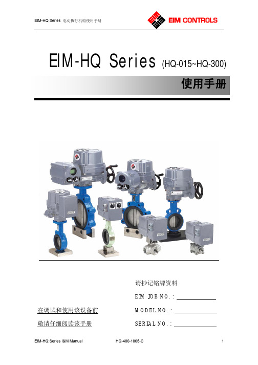
请抄记铭牌资料EIM JOB NO. :MODEL NO. : SERIAL NO. :在调试和使用该设备前 敬请仔细阅读该手册EIM-HQ Series(HQ-015~HQ-300)使用手册目录1.0 概述 (3)2.0 电动执行机构与阀门的装配 (3)3.0 外部结构 (4)4.0 电气接线图 (5)5.0 供电电源 (6)6.0 工作制式 (6)7.0 手动操作 (6)8.0 机械限位的调整 (6)9.0 电气接线 (7)10.0 行程开关的设置 (7)11.0 力矩开关的设置........ (8)12.0 反向运动(逆时针关闭) (8)13.0 润滑 (8)14.0 机械位置指示器(MDPI)的调整 (9)15.0 一般保养 (9)16.0 储藏与存放 (9)17.0 机械接口详细说明 (10)18.0 驱动轴套详细说明 (11)19.0 故障诊断和排除 (12)20.0 HQ系列产品标准功能配置 (13)重要:EIM 公司在对该使用手册的编撰及修订时已经考虑了多方面的使用和应用,然而EIM 公司不保证该手册中的内容无任何错误,也无法对误操作或使用该手册而导致的产品损坏和连带损失负责。
EIM 公司有权利对本手册进行修改,请恕不另行通知。
1.0 概述EIM-HQ系列电动执行机构可以为90º旋转的阀门提供可靠和有效的控制,如球阀,蝶阀及风门挡板等。
警告:在安装、调试、使用和维护HQ系列电动执行机构前,必须仔细阅读本手册,对该产品不熟悉或未阅读本手册前,请勿启动。
警告:当人员在阀门和电动执行机构附近时,必须小心高温、高压、易燃、易爆、有毒、腐蚀性介质和高电压、强大外力等危险状况。
警告:必须严格按照规范、图纸和手册等的要求进行正确的安装、接线、调试、使用、储存和维护,否则有可能导致严重伤害、损坏设备和失去质量保证。
安装之前的检查:仔细核对设备的铭牌信息,必须确认以下参数的正确:型号,力矩,操作速度,电源电压,防护/防爆等级等。
E+H电容物位计FMI21操作说明

20 mA 100 %
FEI20
– 4...20 mA
+
–+
12
+–
2.
z 0.0
z
0…100 %
ᡆ
㔯(gn) 0.5 s
4.0 mA
V=
V~
A
10 s ؍ᆈ
0. 0
0…100 %
ᡆ
㔯(gn) 4s
4.0 mA
V=
V~
A
Endress + Hauser
A
B
1.
2s
–
+
FEI20
– 4...20 mA
W
A661 电子插件温度过高
W
电流输出的影响 优先级
22 mA
1
–
5
22 mA
2
22 mA
3
22 mA
4
6
3.8 mA 20.5 mA
7
8
错误代号
故障 无测量值
测量值错误
红色 LED 指示灯闪烁
原因 无供电电压 信号线故障
电子插件故障 - FEI20 直接连接至 L1 和 N 标定错误 安装的杆式传感器损坏 液体电导率过低 报警 (A) / 警告 (W)
63 % 0.15 s
输出阻尼时间 延迟输出信号时间
t
t 25
技术参数 环境温度 Ta 过程温度 Tp
26
Ta Tp
⍻䟿㋮ᓖ䱽վʽ
Ta
80 70 60 50 40 30 20 10
0
–40 –30 –20 –10 0 10 20 30 40 50 60 70 80 90 100 Tp
–10 –20 –30 –40
E+H超声波流量计93中文简明操作手册

W (DN 15 - 65 / ½ - 2½")
W
捆绑式 捆绑式
捆绑式 ( 焊接螺栓 )
插入式
声速测量传感器
管壁厚度测量 传感器
DDU18 DDU19
捆绑式 捆绑式
行程数 2
1 2 1 2 2
1 2 1 2 1 2 1 –
说明 参考 《简明操作指南》和 CD 中的 《操作手册》 参考 《简明操作指南》和 CD 中的 《操作手册》 参考 CD 中的 《操作手册》
3 安装 . . . . . . . . . . . . . . . . . . . . . . . . . . . . . . . . . . . . . . . . . . . . . . . 6
3.1 安装条件 . . . . . . . . . . . . . . . . . . . . . . . . . . . . . . . . . . . . . . . . . . . . . . . . . . . . . . . . . . . 6 3.2 安装前的准备步骤 . . . . . . . . . . . . . . . . . . . . . . . . . . . . . . . . . . . . . . . . . . . . . . . . . . . 8 3.3 确定所需安装距离 . . . . . . . . . . . . . . . . . . . . . . . . . . . . . . . . . . . . . . . . . . . . . . . . . . . 8 3.4 安装变送器 . . . . . . . . . . . . . . . . . . . . . . . . . . . . . . . . . . . . . . . . . . . . . . . . . . . . . . . . . 9 3.5 连接电源 . . . . . . . . . . . . . . . . . . . . . . . . . . . . . . . . . . . . . . . . . . . . . . . . . . . . . . . . . . 10 3.6 确定安装间距 . . . . . . . . . . . . . . . . . . . . . . . . . . . . . . . . . . . . . . . . . . . . . . . . . . . . . . 12 3.7 机械准备工作 . . . . . . . . . . . . . . . . . . . . . . . . . . . . . . . . . . . . . . . . . . . . . . . . . . . . . . 14 3.8 安装传感器 . . . . . . . . . . . . . . . . . . . . . . . . . . . . . . . . . . . . . . . . . . . . . . . . . . . . . . . . 19 3.9 Prosonic Flow P 和 Prosonic Flow 93W
霍尔特电子产品有限公司 - THERMATTACH双面热接膜产品说明说明书
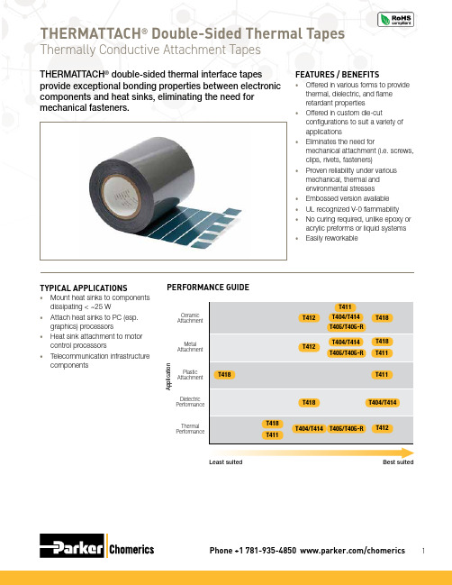
THERMATTACH®Thermally Conductive Attachment TapesOrdering InformationTHERMATTACH ® Thermally Conductive Attachment TapesThese attachment tapes are available on continuous rolls.Ordering Information: Custom ConfigurationsPlease contact Parker Chomerics for a pre-assigned part number, for custom widths, lengths and part sizes, etc.Available options include:• Custom kiss cut parts on sheets, or as individual partsHANDLING INFORMATIONThese products are defined by Parker Chomerics as “articles” according to the following generally recognized regulatory definition for articles:An article is a manufactured item “formed to a specific shape or design during manufacturing,” which has “end use functions” dependent upon its size and shape during end use and which has generally “no change of chemical composition during its end use.”In addition:• T here is no known or anticipated exposure to hazardous materials/substances during routine and anticipated use of the product.• T he product’s shape, surface and design is more relevant than its chemical composition.These materials are not deemed by Parker Chomerics to require an MSDS. For further questions, pleasecontact Parker Chomerics at 781-935-4850.Minimum: 10 psi at room temperature for 15 seconds PREFERRED: 30 psi at room temperature for 5 secondsTHERMATTACH ® Thermally Conductive Attachment TapesTape Application Instructions: T404, T405, T405-R, T411, T412, T413, T414, T418MATERIALS NEEDED•Clean lint-free cloth rag • Industrial solvent • Rubber glovesFor optimal performance, Parker Chomerics recommends interface flatness of 0.001 in/in (0.025 mm/25 mm) to 0.002 in/in (0.050 mm/25 mm) maximum.Step 1: Ensure that bondingsurfaces are free from oil, dust or any contamination that may affect bonding. Using rubber gloves, wipe surfaces with a cloth dampened with industrial solvents such as MEK, toluene, acetone or isopropyl alcohol.Step 2: Cut tape to size* and remove a liner or remove pre-cut tape from roll.*Note: Due to variations in heat sink surfaces, Parker Chomerics’ dataindicates that it sometimes is beneficial to be cut slightly smaller than the area of the heat sink. See illustration.Step 3: Apply to center of heat sink bonding area and smooth over entire surface using moderate hand pressure / rubbing motion. A roller may be useful to help smooth the part to the surface by rolling from the center out to beyond the edges of the part. This ensures optimal contact between tape and heat sink.Step 4: Center heat sink ontocomponent and apply using any one of the recommended temperature/pressure options:More pressure equals better wetting out of the adhesive to the contact surfaces. A twisting motion during assembly of the substrates will typically improve wetting.Note that typically 70% of the ultimate adhesive bond strength is achieved with initial application, and 80-90% is reached within 15 minutes. Ultimate adhesive strength is achieved within 36 hours; however the next manufacturing step can typically occur immediately following the initial application.REMOVAL INSTRUCTIONSMaterials needed: Single-edged razor blade or a small, thin-bladed pocketknife; soft, thin metal spatula. Use safety precautions when handling sharp instruments and organic solvents.Step 1: Carefully insert the blade edge into the bond line at a corner between the heat sink and the component. The penetration need not be very deep.Step 2: Remove the blade and insert the spatula into the wedge. Slowly twist the spatula blade so that it exerts a slight upward pressure.Step 3: As the two surfaces start to separate, move the spatula bladedeeper into the bond line and continue the twisting motion and upward force.Step 4: After the two components are separated, the tape can be removed and discarded. If adhesive remains on the component surfaces, it must be removed. Wipe with a clean rag (lint-free) dabbed with MEK, toluene, or isopropyl alcohol. Use sufficient solvent to remove all adhesive.Step 5: Solvent cleaned components must be verified 100% free of cleaning solvent prior to reattachment of adhesive.* Not RecommendedThermally Conductive Attachment Tapes。
利用微功耗IC实现的低功耗心率监护仪(HRM)详解

利用微功耗IC实现的低功耗心率监护仪(HRM)详解
许多因素决定了病患监护设备需要采用低电压和低功耗工作,因而需要采用低功耗、高精度的IC器件。
其中一个因素是电池的持续使用:在Holter监护仪和其他的便携移动式心电图(ECG)系统中,电池已使用了数十年。
作为唯一的电源,低压电池确保病人(以及设备)在故障条件下不会接触到高电源电压,因此必须使用低功耗IC,以便延长电池寿命。
影响医疗保健用IC的另一个决定性因素是,市场要求提供更多的功能,但又不能增加空间、功耗或者成本。
本文介绍了一款利用微功耗IC实现的低功耗心率监护仪(HRM)。
首先将给
出HRM的定义,并介绍模拟前端,包括主信号链和其他用来实现特殊功能的电路;然后提供一种用于设计FIR(数字有限脉冲响应)滤波器的方法;最后,显示该HRM的实验结果,包括心率计算的精度和HRM的功耗。
心率监护仪(HRM)
HRM是一种个人监护设备,病人可以利用它来实时测量心率,或记录下来
以供日后研究。
HRM的主要功能是计算心率并显示ECG波形,此外还应提供导联脱落检测。
HRM一般是便携式设备,采用电池供电,因此功耗必须很低。
在本文提出的设计中,HRM的模拟前端利用下列器件构建:微功耗仪表放
大器、运算放大器,以及一个内置12位ADC、采样保持放大器和数字处理器的微转换器。
处理后的数据送往PC进行显示。
HRM的模拟前端
图1显示了该设计的系统框图。
微功耗仪表放大器构成了出色的HRM输入放大器,其微功耗、小尺寸、整个频率范围内的高共模抑制比(CMMR)、轨到轨输入和输出等特性非常适合这种应用。
皮肤电位介于0.2mV到2mV.高性能。
- 1、下载文档前请自行甄别文档内容的完整性,平台不提供额外的编辑、内容补充、找答案等附加服务。
- 2、"仅部分预览"的文档,不可在线预览部分如存在完整性等问题,可反馈申请退款(可完整预览的文档不适用该条件!)。
- 3、如文档侵犯您的权益,请联系客服反馈,我们会尽快为您处理(人工客服工作时间:9:00-18:30)。
IEH 发布新的HRM系列连接器产品手册,0.075inch pitch, 2排,3排(1.905mm pitch间距) 高密度连接器
IEH发布了全新的HRM系列连接器产品手册。
HRM系列连接器为0.075英寸(1.905mm)间距的高密度连接器,主要为2排、3排连接器,为hmm 系列的同一家族系列产品。
连接器的应用方式有pcb板的垂直安装、平行板安装、水平板拓展安装、板到线、线到线的应用方式,而且还有丰富的pcb堆叠安装。
总的来说hrm系列有以下特点:
1. 0.075英寸(1.905mm)pitch间距的高密度连接器;
2. 满足美军标MIL-DTL-55302;
3. 0.024英寸(0.6mm)的线簧孔接触件,单针能够过3amp的电流;
4. 过电压为750 vac rms @sea level水平面; 250 vac rms @70,000ft高空;
5. 2排的有10,20,30,40,50,60,70,80,90和100针;
6. 3排的有11, 23, 35, 47, 59, 71, 80, 89, 92, 104, 122, 152和206针可选;
7. 全系列产品都满足美军标55302标准。
8. 主要应用在对可靠性要求很高的航空航天,航海兵器防御的军工应用,以及对可靠性要求高和抗震动、插拔配合次数要求高的工业应用。