APM飞控系统详细介绍
apm飞控入门教程
Apm 飞控较为详细的入门教程最近发现很多模友在看了泡泡老师的视频有很多细节没有看懂在群上提问,为了能使刚用上apm的模友一步到位,再来一个文字教程帮助你们快速使用。
在此也感谢apm2.8交流群中的冷风群主提供的教程~废话不多说了硬件安装1、通过USB接口供电时,如果USB数据处于连接状态,APM会切断数传接口的通讯功能,所以请不要同时使用数传和USB线连接调试APM,USB接口的优先级高于数传接口,仅有供电功能的USB线不在此限;2、APM板载的加速度传感器受震动影响,会产生不必要的动差,直接影响飞控姿态的计算,条件允许请尽量使用一个减震平台来安装APM主板;3、APM板载的高精气压计对温度的变化非常敏感,所以请尽量在气压计上覆盖一块黑色海绵用来遮光,以避免阳光直射的室外飞行环境下,光照热辐射对气压计的影响。
另外覆盖海绵,也可以避免飞行器自身气流对气压计的干扰。
使用建议对于初次使用APM自驾仪的用户来说,建议你分步骤完成APM的入门使用:1、首先安装地面站控制软件及驱动,熟悉地面站界面的各个菜单功能;2、仅连接USB线学会固件的下载;3、连接接收机和USB线完成APM的遥控校准、加速度校准和罗盘校准;4、完成各类参数的设定;5、组装飞机,完成各类安全检查后试飞;6、PID参数调整;7、APM各类高阶应用地面站调试软件Mission Planner安装首先,MissionPlanner的安装运行需要微软的Net Framework 4.0组件,所以在安装Mission Planner之前请先下载Net Flamework 4.0并安装安装完NetFramework后开始下载Mission Planner安装程序包,最新版本的Mission Planner可以点击此处下载,下载页面中每个版本都提供了MSI版和ZIP版可供选择。
MSI 为应用程序安装包版,安装过程中会同时安装APM的USB驱动,安装后插上APM的USB 线即可使用。
APM飞控介绍
Ardupilot飞控示意图
地面站软件系统
Ardupilot系统的地面控制站是一个运行在地面上
电脑中的应用程序,通过无线通信模块与无人机通 信,显示无人机实时性能和位置,显示载机仪表面 盘,实时发送飞行过程控制指令,上传新的任务命 令和设定参数,显示航拍实时视频流。目前较成熟 的Ardupilot地面站软件包括:APM Mission Planner、HappyKillmore、QGroundControl。
机械部分(无人机/汽车/机械手臂) Microcontroller(Arduino)
Serial Port/有线/无线网络
Server
Database:Sqlserver/Oracle/DB2
1. Web services (c#/VB/java/python) 2. Form Application(c#/VB/java/python)
相关技术说明
Arduino:是一个开放源代码的单芯片微电脑,它
使用了Atmel AVR单片机,采用了基于开放源代码 的软硬件平台,构建于开放源代码 simple I/O 接 口板,并且具有使用类似Java、C 语言的 Processing/Wiring开发环境。 MAVLINK:Micro Air Vehicle Link是一个用于小 型无人机的通信协议. 它是一个只有头文件信息的 类型库列集,MAVlink最早以 LGPL协议在2009年发 布。MAVLINK主要被用于地面站和无人机间通信, 可以用来传递方向、GPS位置、速度等信息。
一种开源的航空电磁法运载工具: Ardupilot无人机系统
江苏大学 计算机科学与通信工程学院 通信工程系 朱轶
无人机简介
无人机(Unmanned Aerial Vehicle,UAV)指借助遥
APM飞控源码讲解

APM飞控系统介绍APM飞控系统是国外的一个开源飞控系统,能够支持固定翼,直升机,3轴,4轴,6轴飞行器。
在此我只介绍固定翼飞控系统。
飞控原理在APM飞控系统中,采用的是两级PID控制方式,第一级是导航级,第二级是控制级,导航级的计算集中在medium_loop( ) 和fastloop( )的update_current_flight_mode( )函数中,控制级集中在fastloop( )的stabilize( )函数中。
导航级PID控制就是要解决飞机如何以预定空速飞行在预定高度的问题,以及如何转弯飞往目标问题,通过算法给出飞机需要的俯仰角、油门和横滚角,然后交给控制级进行控制解算。
控制级的任务就是依据需要的俯仰角、油门、横滚角,结合飞机当前的姿态解算出合适的舵机控制量,使飞机保持预定的俯仰角,横滚角和方向角。
最后通过舵机控制级set_servos_4( )将控制量转换成具体的pwm信号量输出给舵机。
值得一提的是,油门的控制量是在导航级确定的。
控制级中不对油门控制量进行解算,而直接交给舵机控制级。
而对于方向舵的控制,导航级并不给出方向舵量的解算,而是由控制级直接解算方向舵控制量,然后再交给舵机控制级。
以下,我剔除了APM飞控系统的细枝末节,仅仅将飞控系统的重要语句展现,只浅显易懂地说明APM飞控系统的核心工作原理。
一,如何让飞机保持预定高度和空速飞行要想让飞机在预定高度飞行,飞控必须控制好飞机的升降舵和油门,因此,首先介绍固定翼升降舵和油门的控制,固定翼的升降舵和油门控制方式主要有两种:一种是高度控制油门,空速控制升降舵方式。
实际飞行存在四种情况,第一种情况是飞机飞行过程中,如果高度低于目标高度,飞控就会控制油门加大,从而导致空速加大,然后才导致拉升降舵,飞机爬升;第二种情况与第一种情况相反;第三种情况是飞机在目标高度,但是空速高于目标空速,这种情况飞控会直接拉升降舵,使飞机爬升,降低空速,但是,高度增加了,飞控又会减小油门,导致空速降低,空速低于目标空速后,飞控推升降舵,导致飞机降低高度。
APM飞控程序解读

/// -*- tab-width: 4; Mode: C++; c-basic-offset: 4; indent-tabs-mode: nil -*-#define THISFIRMWARE "ArduCopter V3.1-rc5"/*This program is free software: you can redistribute it and/or modifyit under the terms of the GNU General Public License as published bythe Free Software Foundation, either version 3 of the License, or(at your option) any later version.This program is distributed in the hope that it will be useful,but WITHOUT ANY WARRANTY; without even the implied warranty ofMERCHANTABILITY or FITNESS FOR A PARTICULAR PURPOSE. See theGNU General Public License for more details.You should have received a copy of the GNU General Public Licensealong with this program. If not, see </licenses/>.*//** ArduCopter Version 3.0* Creator: Jason Short* Lead Developer: Randy Mackay* Based on code and ideas from the Arducopter team: Pat Hickey, Jose Julio, Jani Hirvinen, Andrew Tridgell, Justin Beech, Adam Rivera, Jean-Louis Naudin, Roberto Navoni* Thanks to: Chris Anderson, Mike Smith, Jordi Munoz, Doug Weibel, James Goppert, Benjamin Pelletier, Robert Lefebvre, Marco Robustini** Special Thanks for Contributors (in alphabetical order by first name):** Adam M Rivera :Auto Compass Declination* Amilcar Lucas :Camera mount library* Andrew Tridgell :General development, Mavlink Support* Angel Fernandez :Alpha testing* Doug Weibel :Libraries* Christof Schmid :Alpha testing* Dani Saez :V Octo Support* Gregory Fletcher :Camera mount orientation math* Guntars :Arming safety suggestion* HappyKillmore :Mavlink GCS* Hein Hollander :Octo Support* Igor van Airde :Control Law optimization* Leonard Hall :Flight Dynamics, Throttle, Loiter and Navigation Controllers* Jonathan Challinger :Inertial Navigation* Jean-Louis Naudin :Auto Landing* Max Levine :Tri Support, Graphics* Jack Dunkle :Alpha testing* James Goppert :Mavlink Support* Jani Hiriven :Testing feedback* John Arne Birkeland :PPM Encoder* Jose Julio :Stabilization Control laws* Marco Robustini :Lead tester* Michael Oborne :Mission Planner GCS* Mike Smith :Libraries, Coding support* Oliver :Piezo support* Olivier Adler :PPM Encoder* Robert Lefebvre :Heli Support & LEDs* Sandro Benigno :Camera support** And much more so PLEASE PM me on DIYDRONES to add your contribution to the List** Requires modified "mrelax" version of Arduino, which can be found here:* /p/ardupilot-mega/downloads/list*////////////////////////////////////////////////////////////////////////////////// Header includes////////////////////////////////////////////////////////////////////////////////#include <math.h>#include <stdio.h>#include <stdarg.h>// Common dependencies#include <AP_Common.h>#include <AP_Progmem.h>#include <AP_Menu.h>#include <AP_Param.h>// AP_HAL#include <AP_HAL.h>#include <AP_HAL_AVR.h>#include <AP_HAL_AVR_SITL.h>#include <AP_HAL_PX4.h>#include <AP_HAL_FLYMAPLE.h>#include <AP_HAL_Linux.h>#include <AP_HAL_Empty.h>// Application dependencies#include <GCS_MAVLink.h> // MAVLink GCS definitions#include <AP_GPS.h> // ArduPilot GPS library#include <AP_GPS_Glitch.h> // 全球定位系统干扰保护库#include <DataFlash.h> // ArduPilot Mega Flash Memory Library#include <AP_ADC.h> // ArduPilot Mega Analog to Digital Converter Library#include <AP_ADC_AnalogSource.h>#include <AP_Baro.h>#include <AP_Compass.h> // ArduPilot Mega Magnetometer Library#include <AP_Math.h> // ArduPilot Mega Vector/Matrix math Library#include <AP_Curve.h> // Curve used to linearlise throttle pwm to thrust#include <AP_InertialSensor.h> // ArduPilot Mega Inertial Sensor (accel & gyro) Library #include <AP_AHRS.h>#include <APM_PI.h> // PI library#include <AC_PID.h> // PID library#include <RC_Channel.h> //遥控通道库#include <AP_Motors.h> // AP Motors library#include <AP_RangeFinder.h> // Range finder library#include <AP_OpticalFlow.h> // Optical Flow library#include <Filter.h> // Filter library#include <AP_Buffer.h> // APM FIFO Buffer#include <AP_Relay.h> // APM relay#include <AP_Camera.h> // Photo or video camera#include <AP_Mount.h> // Camera/Antenna mount#include <AP_Airspeed.h> // needed for AHRS build#include <AP_Vehicle.h> // needed for AHRS build#include <AP_InertialNav.h> // ArduPilot Mega inertial 导航 library#include <AC_WPNav.h> // ArduCopter waypoint navigation library#include <AP_Declination.h> // ArduPilot Mega Declination Helper Library#include <AC_Fence.h> // Arducopter Fence library#include <memcheck.h> // memory limit checker#include <SITL.h> // software in the loop support#include <AP_Scheduler.h> // 主循环调度程序#include <AP_RCMapper.h> // RC input mapping library#include <AP_Notify.h> // Notify library#include <AP_BattMonitor.h> // Battery monitor library#if SPRAYER == ENABLED#include <AC_Sprayer.h> // crop sprayer library// AP_HAL to Arduino compatibility layer#include "compat.h"// Configuration#include "defines.h"#include "config.h"#include "config_channels.h"// Local modules#include "Parameters.h"#include "GCS.h"//////////////////////////////////////////////////////////////////////////////// // cliSerial//////////////////////////////////////////////////////////////////////////////// // cliSerial isn't strictly necessary - it is an alias for hal.console. It may // be deprecated in favor of hal.console in later releases.static AP_HAL::BetterStream* cliSerial;// N.B. we need to keep a static declaration which isn't guarded by macros// at the top to cooperate with the prototype mangler.//////////////////////////////////////////////////////////////////////////////// // AP_HAL instance//////////////////////////////////////////////////////////////////////////////// const AP_HAL::HAL& hal = AP_HAL_BOARD_DRIVER;//////////////////////////////////////////////////////////////////////////////// // Parameters//////////////////////////////////////////////////////////////////////////////// //// Global parameters are all contained within the 'g' class.//static Parameters g;// main loop schedulerstatic AP_Scheduler scheduler;// AP_Notify instancestatic AP_Notify notify;//////////////////////////////////////////////////////////////////////////////// // prototypes//////////////////////////////////////////////////////////////////////////////// static void update_events(void);static void print_flight_mode(AP_HAL::BetterStream *port, uint8_t mode);//////////////////////////////////////////////////////////////////////////////// // Dataflash//////////////////////////////////////////////////////////////////////////////// #if CONFIG_HAL_BOARD == HAL_BOARD_APM2static DataFlash_APM2 DataFlash;#elif CONFIG_HAL_BOARD == HAL_BOARD_APM1static DataFlash_APM1 DataFlash;#elif CONFIG_HAL_BOARD == HAL_BOARD_AVR_SITL//static DataFlash_File DataFlash("/tmp/APMlogs");static DataFlash_SITL DataFlash;#elif CONFIG_HAL_BOARD == HAL_BOARD_PX4static DataFlash_File DataFlash("/fs/microsd/APM/logs");#elif CONFIG_HAL_BOARD == HAL_BOARD_LINUXstatic DataFlash_File DataFlash("logs");#elsestatic DataFlash_Empty DataFlash;#endif////////////////////////////////////////////////////////////////////////////////// the rate we run the main loop at////////////////////////////////////////////////////////////////////////////////static const AP_InertialSensor::Sample_rate ins_sample_rate = AP_InertialSensor::RATE_100HZ;////////////////////////////////////////////////////////////////////////////////// Sensors//////////////////////////////////////////////////////////////////////////////////// There are three basic options related to flight sensor selection.//// - Normal flight mode. Real sensors are used.// - HIL Attitude mode. Most sensors are disabled, as the HIL// protocol supplies attitude information directly.// - HIL Sensors mode. Synthetic sensors are configured that// supply data from the simulation.//// All GPS access should be through this pointer.static GPS *g_gps;static GPS_Glitch gps_glitch(g_gps);// flight modes convenience arraystatic AP_Int8 *flight_modes = &g.flight_mode1;#if HIL_MODE == HIL_MODE_DISABLED#if CONFIG_ADC == ENABLEDstatic AP_ADC_ADS7844 adc;#endif#if CONFIG_IMU_TYPE == CONFIG_IMU_MPU6000static AP_InertialSensor_MPU6000 ins;#elif CONFIG_IMU_TYPE == CONFIG_IMU_OILPANstatic AP_InertialSensor_Oilpan ins(&adc);#elif CONFIG_IMU_TYPE == CONFIG_IMU_SITLstatic AP_InertialSensor_HIL ins;#elif CONFIG_IMU_TYPE == CONFIG_IMU_PX4static AP_InertialSensor_PX4 ins;#elif CONFIG_IMU_TYPE == CONFIG_IMU_FLYMAPLEAP_InertialSensor_Flymaple ins;#elif CONFIG_IMU_TYPE == CONFIG_IMU_L3G4200DAP_InertialSensor_L3G4200D ins;#endif#if CONFIG_HAL_BOARD == HAL_BOARD_AVR_SITL// When building for SITL we use the HIL barometer and compass driversstatic AP_Baro_HIL barometer;static AP_Compass_HIL compass;static SITL sitl;#else// Otherwise, instantiate a real barometer and compass driver#if CONFIG_BARO == AP_BARO_BMP085static AP_Baro_BMP085 barometer;#elif CONFIG_BARO == AP_BARO_PX4static AP_Baro_PX4 barometer;#elif CONFIG_BARO == AP_BARO_MS5611#if CONFIG_MS5611_SERIAL == AP_BARO_MS5611_SPIstatic AP_Baro_MS5611 barometer(&AP_Baro_MS5611::spi);#elif CONFIG_MS5611_SERIAL == AP_BARO_MS5611_I2Cstatic AP_Baro_MS5611 barometer(&AP_Baro_MS5611::i2c);#else#error Unrecognized CONFIG_MS5611_SERIAL setting.#endif#endif#if CONFIG_HAL_BOARD == HAL_BOARD_PX4static AP_Compass_PX4 compass;#elsestatic AP_Compass_HMC5843 compass;#endif#endif// real GPS selection#if GPS_PROTOCOL == GPS_PROTOCOL_AUTOAP_GPS_Auto g_gps_driver(&g_gps);#elif GPS_PROTOCOL == GPS_PROTOCOL_NMEAAP_GPS_NMEA g_gps_driver;#elif GPS_PROTOCOL == GPS_PROTOCOL_SIRFAP_GPS_SIRF g_gps_driver;#elif GPS_PROTOCOL == GPS_PROTOCOL_UBLOXAP_GPS_UBLOX g_gps_driver;#elif GPS_PROTOCOL == GPS_PROTOCOL_MTKAP_GPS_MTK g_gps_driver;#elif GPS_PROTOCOL == GPS_PROTOCOL_MTK19AP_GPS_MTK19 g_gps_driver;#elif GPS_PROTOCOL == GPS_PROTOCOL_NONEAP_GPS_None g_gps_driver;#else#error Unrecognised GPS_PROTOCOL setting.#endif // GPS PROTOCOLstatic AP_AHRS_DCM ahrs(&ins, g_gps);#elif HIL_MODE == HIL_MODE_SENSORS// sensor emulatorsstatic AP_ADC_HIL adc;static AP_Baro_HIL barometer;static AP_Compass_HIL compass;static AP_GPS_HIL g_gps_driver;static AP_InertialSensor_HIL ins;static AP_AHRS_DCM ahrs(&ins, g_gps);#if CONFIG_HAL_BOARD == HAL_BOARD_AVR_SITL// When building for SITL we use the HIL barometer and compass drivers static SITL sitl;#endif#elif HIL_MODE == HIL_MODE_ATTITUDEstatic AP_ADC_HIL adc;static AP_InertialSensor_HIL ins;static AP_AHRS_HIL ahrs(&ins, g_gps);static AP_GPS_HIL g_gps_driver;static AP_Compass_HIL compass; // never usedstatic AP_Baro_HIL barometer;#if CONFIG_HAL_BOARD == HAL_BOARD_AVR_SITL// When building for SITL we use the HIL barometer and compass driversstatic SITL sitl;#endif#else#error Unrecognised HIL_MODE setting.#endif // HIL MODE////////////////////////////////////////////////////////////////////////////////// Optical flow sensor////////////////////////////////////////////////////////////////////////////////#if OPTFLOW == ENABLEDstatic AP_OpticalFlow_ADNS3080 optflow;#elsestatic AP_OpticalFlow optflow;#endif////////////////////////////////////////////////////////////////////////////////// GCS selection////////////////////////////////////////////////////////////////////////////////static GCS_MAVLINK gcs0;static GCS_MAVLINK gcs3;////////////////////////////////////////////////////////////////////////////////// SONAR selection//////////////////////////////////////////////////////////////////////////////////ModeFilterInt16_Size3 sonar_mode_filter(1);#if CONFIG_SONAR == ENABLEDstatic AP_HAL::AnalogSource *sonar_analog_source;static AP_RangeFinder_MaxsonarXL *sonar;#endif////////////////////////////////////////////////////////////////////////////////// User variables////////////////////////////////////////////////////////////////////////////////#ifdef USERHOOK_VARIABLES#include USERHOOK_VARIABLES#endif////////////////////////////////////////////////////////////////////////////////// Global variables/////////////////////////////////////////////////////////////////////////////////* Radio values* Channel assignments* 1 Ailerons (rudder if no ailerons)* 2 Elevator* 3 Throttle* 4 Rudder (if we have ailerons)* 5 Mode - 3 position switch* 6 User assignable* 7 trainer switch - sets throttle nominal (toggle switch), sets accels to Level (hold >1 second)* 8 TBD* Each Aux channel can be configured to have any of the available auxiliary functions assigned to it.* See libraries/RC_Channel/RC_Channel_aux.h for more information*///Documentation of GLobals:static union {struct {uint8_t home_is_set : 1; // 0uint8_t simple_mode : 2; // 1,2 // This is the state of simple mode : 0 = disabled ; 1 = SIMPLE ;2 = SUPERSIMPLEuint8_t pre_arm_rc_check : 1; // 3 // true if rc input pre-arm checks have been completed successfully uint8_t pre_arm_check : 1; // 4 // true if all pre-arm checks (rc, accel calibration, gps lock) have been performeduint8_t auto_armed : 1; // 5 // stops auto missions from beginning until throttle is raised uint8_t logging_started : 1; // 6 // true if dataflash logging has starteduint8_t do_flip : 1; // 7 // Used to enable flip codeuint8_t takeoff_complete : 1; // 8uint8_t land_complete : 1; // 9 // true if we have detected a landinguint8_t new_radio_frame : 1; // 10 // Set true if we have new PWM data to act on from the Radio uint8_t CH7_flag : 2; // 11,12 // ch7 aux switch : 0 is low or false, 1 is center or true, 2 is highuint8_t CH8_flag : 2; // 13,14 // ch8 aux switch : 0 is low or false, 1 is center or true, 2 is highuint8_t usb_connected : 1; // 15 // true if APM is powered from USB connectionuint8_t yaw_stopped : 1; // 16 // Used to manage the Yaw hold capabilitiesuint8_t disable_stab_rate_limit : 1; // 17 // disables limits rate request from the stability controlleruint8_t rc_receiver_present : 1; // 18 // true if we have an rc receiver present (i.e. if we've ever received an update};uint32_t value;} ap;////////////////////////////////////////////////////////////////////////////////// Radio////////////////////////////////////////////////////////////////////////////////// This is the state of the flight control system// There are multiple states defined such as STABILIZE, ACRO,static int8_t control_mode = STABILIZE;// Used to maintain the state of the previous control switch position// This is set to -1 when we need to re-read the switchstatic uint8_t oldSwitchPosition;static RCMapper rcmap;// receiver RSSIstatic uint8_t receiver_rssi;////////////////////////////////////////////////////////////////////////////////// Failsafe////////////////////////////////////////////////////////////////////////////////static struct {uint8_t rc_override_active : 1; // 0 // true if rc control are overwritten by ground stationuint8_t radio : 1; // 1 // A status flag for the radio failsafeuint8_t battery : 1; // 2 // A status flag for the battery failsafeuint8_t gps : 1; // 3 // A status flag for the gps failsafeuint8_t gcs : 1; // 4 // A status flag for the ground station failsafeint8_t radio_counter; // number of iterations with throttle below throttle_fs_valueuint32_t last_heartbeat_ms; // the time when the last HEARTBEAT message arrived from a GCS - used for triggering gcs failsafe} failsafe;////////////////////////////////////////////////////////////////////////////////// Motor Output////////////////////////////////////////////////////////////////////////////////#if FRAME_CONFIG == QUAD_FRAME#define MOTOR_CLASS AP_MotorsQuad#elif FRAME_CONFIG == TRI_FRAME#define MOTOR_CLASS AP_MotorsTri#elif FRAME_CONFIG == HEXA_FRAME#define MOTOR_CLASS AP_MotorsHexa#elif FRAME_CONFIG == Y6_FRAME#define MOTOR_CLASS AP_MotorsY6#elif FRAME_CONFIG == OCTA_FRAME#define MOTOR_CLASS AP_MotorsOcta#elif FRAME_CONFIG == OCTA_QUAD_FRAME#define MOTOR_CLASS AP_MotorsOctaQuad#elif FRAME_CONFIG == HELI_FRAME#define MOTOR_CLASS AP_MotorsHeli#else#error Unrecognised frame type#endif#if FRAME_CONFIG == HELI_FRAME // helicopter constructor requires more argumentsstatic MOTOR_CLASS motors(&g.rc_1, &g.rc_2, &g.rc_3, &g.rc_4, &g.rc_8, &g.heli_servo_1, &g.heli_servo_2,&g.heli_servo_3, &g.heli_servo_4);#elif FRAME_CONFIG == TRI_FRAME // tri constructor requires additional rc_7 argument to allow tail servo reversing static MOTOR_CLASS motors(&g.rc_1, &g.rc_2, &g.rc_3, &g.rc_4, &g.rc_7);#elsestatic MOTOR_CLASS motors(&g.rc_1, &g.rc_2, &g.rc_3, &g.rc_4);#endif////////////////////////////////////////////////////////////////////////////////// PIDs////////////////////////////////////////////////////////////////////////////////// This is a convienience accessor for the IMU roll rates. It's currently the raw IMU rates// and not the adjusted omega rates, but the name is stuckstatic Vector3f omega;// This is used to hold radio tuning values for in-flight CH6 tuningfloat tuning_value;// used to limit the rate that the pid controller output is logged so that it doesn't negatively affect performance static uint8_t pid_log_counter;////////////////////////////////////////////////////////////////////////////////// LED output////////////////////////////////////////////////////////////////////////////////// Blinking indicates GPS statusstatic uint8_t copter_leds_GPS_blink;// Blinking indicates battery statusstatic uint8_t copter_leds_motor_blink;// Navigation confirmation blinksstatic int8_t copter_leds_nav_blink;////////////////////////////////////////////////////////////////////////////////// GPS variables////////////////////////////////////////////////////////////////////////////////// This is used to scale GPS values for EEPROM storage// 10^7 times Decimal GPS means 1 == 1cm// This approximation makes calculations integer and it's easy to readstatic const float t7 = 10000000.0;// We use atan2 and other trig techniques to calaculate angles// We need to scale the longitude up to make these calcs work// to account for decreasing distance between lines of longitude away from the equatorstatic float scaleLongUp = 1;// Sometimes we need to remove the scaling for distance calcsstatic float scaleLongDown = 1;////////////////////////////////////////////////////////////////////////////////// Location & Navigation////////////////////////////////////////////////////////////////////////////////// This is the angle from the copter to the next waypoint in centi-degreesstatic int32_t wp_bearing;// The original bearing to the next waypoint. used to point the nose of the copter at the next waypoint static int32_t original_wp_bearing;// The location of home in relation to the copter in centi-degreesstatic int32_t home_bearing;// distance between plane and home in cmstatic int32_t home_distance;// distance between plane and next waypoint in cm.static uint32_t wp_distance;// navigation mode - options include NAV_NONE, NAV_LOITER, NAV_CIRCLE, NAV_WPstatic uint8_t nav_mode;// Register containing the index of the current navigation command in the mission scriptstatic int16_t command_nav_index;// Register containing the index of the previous navigation command in the mission script// Used to manage the execution of conditional commandsstatic uint8_t prev_nav_index;// Register containing the index of the current conditional command in the mission scriptstatic uint8_t command_cond_index;// Used to track the required WP navigation information// options include// NAV_ALTITUDE - have we reached the desired altitude?// NAV_LOCATION - have we reached the desired location?// NAV_DELAY - have we waited at the waypoint the desired time?static float lon_error, lat_error; // Used to report how many cm we are from the next waypoint or loiter target positionstatic int16_t control_roll;static int16_t control_pitch;static uint8_t rtl_state; // records state of rtl (initial climb, returning home, etc)static uint8_t land_state; // records state of land (flying to location, descending)////////////////////////////////////////////////////////////////////////////////// Orientation(方向)////////////////////////////////////////////////////////////////////////////////// Convienience accessors for commonly used trig functions. These values are generated// by the DCM through a few simple equations. They are used throughout the code where cos and sin// would normally be used.// The cos values are defaulted to 1 to get a decent initial value for a level statestatic float cos_roll_x = 1.0;static float cos_pitch_x = 1.0;static float cos_yaw = 1.0;static float sin_yaw;static float sin_roll;static float sin_pitch;////////////////////////////////////////////////////////////////////////////////// SIMPLE Mode////////////////////////////////////////////////////////////////////////////////// Used to track the orientation of the copter for Simple mode. This value is reset at each arming// or in SuperSimple mode when the copter leaves a 20m radius from home.static float simple_cos_yaw = 1.0;static float simple_sin_yaw;static int32_t super_simple_last_bearing;static float super_simple_cos_yaw = 1.0;static float super_simple_sin_yaw;// Stores initial bearing when armed - initial simple bearing is modified in super simple mode so not suitable static int32_t initial_armed_bearing;////////////////////////////////////////////////////////////////////////////////// Rate contoller targets////////////////////////////////////////////////////////////////////////////////static uint8_t rate_targets_frame = EARTH_FRAME; // indicates whether rate targets provided in earth or body framestatic int32_t roll_rate_target_ef;static int32_t pitch_rate_target_ef;static int32_t yaw_rate_target_ef;static int32_t roll_rate_target_bf; // body frame roll rate targetstatic int32_t pitch_rate_target_bf; // body frame pitch rate targetstatic int32_t yaw_rate_target_bf; // body frame yaw rate target////////////////////////////////////////////////////////////////////////////////// Throttle(风门,调节) variables////////////////////////////////////////////////////////////////////////////////static int16_t throttle_accel_target_ef; // earth frame throttle acceleration targetstatic bool throttle_accel_controller_active; // true when accel based throttle controller is active, false when higher level throttle controllers are providing throttle output directlystatic float throttle_avg; // g.throttle_cruise as a floatstatic int16_t desired_climb_rate; // pilot desired climb rate - for logging purposes onlystatic float target_alt_for_reporting; // target altitude in cm for reporting (logs and ground station)////////////////////////////////////////////////////////////////////////////////// ACRO(高) Mode////////////////////////////////////////////////////////////////////////////////// Used to control Axis lockstatic int32_t acro_roll; // desired roll angle while sport modestatic int32_t acro_roll_rate; // desired roll rate while in acro modestatic int32_t acro_pitch; // desired pitch angle while sport modestatic int32_t acro_pitch_rate; // desired pitch rate while acro modestatic int32_t acro_yaw_rate; // desired yaw rate while acro modestatic float acro_level_mix; // scales back roll, pitch and yaw inversely proportional to input from pilot// Filters#if FRAME_CONFIG == HELI_FRAME//static LowPassFilterFloat rate_roll_filter; // Rate Roll filter//static LowPassFilterFloat rate_pitch_filter; // Rate Pitch filter#endif // HELI_FRAME////////////////////////////////////////////////////////////////////////////////// Circle Mode / Loiter(走停) control////////////////////////////////////////////////////////////////////////////////Vector3f circle_center; // circle position expressed in cm from home location. x = lat, y = lon// angle from the circle center to the copter's desired location. Incremented at circle_rate / secondstatic float circle_angle;// the total angle (in radians) travelledstatic float circle_angle_total;// deg : how many times to circle as specified by mission commandstatic uint8_t circle_desired_rotations;static float circle_angular_acceleration; // circle mode's angular accelerationstatic float circle_angular_velocity; // circle mode's angular velocitystatic float circle_angular_velocity_max; // circle mode's max angular velocity// How long we should stay in Loiter Mode for mission scripting (time in seconds)static uint16_t loiter_time_max;// How long have we been loitering - The start time in millisstatic uint32_t loiter_time;////////////////////////////////////////////////////////////////////////////////// CH7 and CH8 save waypoint(航路点) control////////////////////////////////////////////////////////////////////////////////// This register tracks the current Mission Command index when writing// a mission using Ch7 or Ch8 aux switches in flightstatic int8_t aux_switch_wp_index;////////////////////////////////////////////////////////////////////////////////// Battery Sensors////////////////////////////////////////////////////////////////////////////////static AP_BattMonitor battery;////////////////////////////////////////////////////////////////////////////////// Altitude////////////////////////////////////////////////////////////////////////////////// The (throttle) controller desired altitude in cmstatic float controller_desired_alt;// The cm we are off in altitude from next_WP.alt – Positive value means we are below the WP static int32_t altitude_error;// The cm/s we are moving up or down based on filtered data - Positive = UPstatic int16_t climb_rate;// The altitude as reported by Sonar in cm – Values are 20 to 700 generally.static int16_t sonar_alt;static uint8_t sonar_alt_health; // true if we can trust the altitude from the sonarstatic float target_sonar_alt; // desired altitude in cm above the ground// The altitude as reported by Baro in cm – Values can be quite highstatic int32_t baro_alt;static int16_t saved_toy_throttle;////////////////////////////////////////////////////////////////////////////////// flight modes////////////////////////////////////////////////////////////////////////////////// Flight modes are combinations of Roll/Pitch, Yaw and Throttle control modes// Each Flight mode is a unique combination of these modes//// The current desired control scheme for Yawstatic uint8_t yaw_mode;// The current desired control scheme for roll and pitch / navigationstatic uint8_t roll_pitch_mode;// The current desired control scheme for altitude holdstatic uint8_t throttle_mode;////////////////////////////////////////////////////////////////////////////////// flight specific////////////////////////////////////////////////////////////////////////////////// An additional throttle added to keep the copter at the same altitude when banking。
详细的APM飞控调试资料
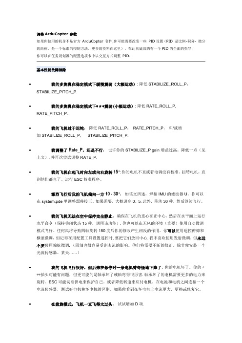
调整ArduCopter 参数如果你使用的机身不是官方ArduCopter 套件,你可能需要改变一些PID设置(PID 是比例-积分- 微分的简称,是一个标准的控制方法。
更多的资料在这里)。
在此页底部的有一个PID的全面的指导.你可以在任务规划器的配置选项卡中以交互方式调整PID:基本性能故障排除•我的多旋翼在稳定模式下缓慢震荡(大幅运动): 降低 STABILIZE_ROLL_P,STABILIZE_PITCH_P.•我的多旋翼在稳定模式下***震荡(小幅运动): 降低 RATE_ROLL_P, RATE_PITCH_P。
•我的飞机过于迟钝:降低 RATE_ROLL_P,RATE_PITCH_P,和/或增加 STABILIZE_ROLL_P, STABILIZE_PITCH_P.•我调整了 Rate_P,还是不行:也许你的 STABILIZE_P gain 增益过高。
降低一点(见上文),并再次尝试调整 RATE_P.•我的飞机在起飞时向左或向右旋转15°:你的电机不直或着电调没有校准。
扭转电机,直到他们都直了。
运行ESC校准程序。
•激烈飞行后我的飞机偏向一方 10 - 30°:如该文所述,焊接 IMU 的滤波器U。
你可以在 system.pde 里调整漂移校正。
如果需要,大概调高0。
5.此外,降落30秒,然后继续飞行。
•我的飞机无法在空中保持完全静止:确保在飞机的重心在正中心。
然后在水平面上运行水平命令(保持关闭状态15秒,调用该功能).你也可以在无风的环境(重要)使用自动微调模式飞行。
任何风将导致四轴旋转180度后你的修改产生相反的作用。
你可以使用遥控俯仰和横滚微调,但记得在用配置工具设置遥控时,要把它们放回中心.我不喜欢使用发射微调,但永远不要使用偏航微调.(四轴也很容易受到紊流的影响。
他们将需要不断的修正,除非你安装一个光流传感器。
某天……)•我的飞机飞行很好,但后来在悬停时一条电机臂奇怪地下降了:你的电机坏了。
APM飞控介绍范文
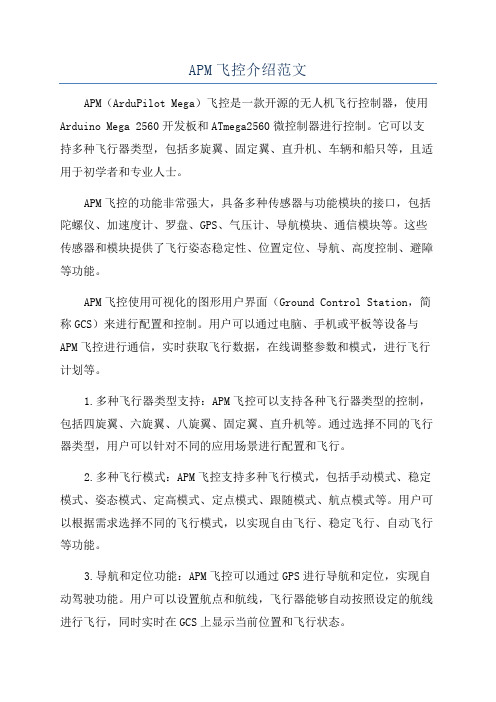
APM飞控介绍范文APM(ArduPilot Mega)飞控是一款开源的无人机飞行控制器,使用Arduino Mega 2560开发板和ATmega2560微控制器进行控制。
它可以支持多种飞行器类型,包括多旋翼、固定翼、直升机、车辆和船只等,且适用于初学者和专业人士。
APM飞控的功能非常强大,具备多种传感器与功能模块的接口,包括陀螺仪、加速度计、罗盘、GPS、气压计、导航模块、通信模块等。
这些传感器和模块提供了飞行姿态稳定性、位置定位、导航、高度控制、避障等功能。
APM飞控使用可视化的图形用户界面(Ground Control Station,简称GCS)来进行配置和控制。
用户可以通过电脑、手机或平板等设备与APM飞控进行通信,实时获取飞行数据,在线调整参数和模式,进行飞行计划等。
1.多种飞行器类型支持:APM飞控可以支持各种飞行器类型的控制,包括四旋翼、六旋翼、八旋翼、固定翼、直升机等。
通过选择不同的飞行器类型,用户可以针对不同的应用场景进行配置和飞行。
2.多种飞行模式:APM飞控支持多种飞行模式,包括手动模式、稳定模式、姿态模式、定高模式、定点模式、跟随模式、航点模式等。
用户可以根据需求选择不同的飞行模式,以实现自由飞行、稳定飞行、自动飞行等功能。
3.导航和定位功能:APM飞控可以通过GPS进行导航和定位,实现自动驾驶功能。
用户可以设置航点和航线,飞行器能够自动按照设定的航线进行飞行,同时实时在GCS上显示当前位置和飞行状态。
4.传感器和稳定性:APM飞控配备了陀螺仪、加速度计和罗盘等传感器,能够实时获取飞行器的姿态信息。
通过PID控制算法和传感器反馈,可以实现飞行器的姿态稳定和控制。
5.遥控器和数据链路:APM飞控支持与遥控器和数据链路进行通信和控制。
用户可以通过遥控器操控飞行器的飞行,实现手动控制、姿态控制等功能。
同时,用户还可以通过数据链路将APM飞控与地面站进行通信,实时获取飞行数据和调整参数。
APM飞行模式解说
APM飞行模式注解ELEV是俯仰或升降 1通道对 PitchAILE是横滚或副翼 2通道对 RollTHRO是油门 3通道对 ThrottlRUDD是方向 4通道对 Yaw红正黑负白信号,红正棕负橙信号Pitch 俯仰 Roll 横滚 Throttl 油门 Yaw 方向1、稳定模式Stabilize稳定模式是使用得最多的飞行模式,也是最基本的飞行模式,起飞和降落都应该使用此模式。
此模式下,飞控会让飞行器保持稳定,是初学者进行一般飞行的首选,也是FPV第一视角飞行的最佳模式。
一定要确保遥控器上的开关能很方便无误地拨到该模式,应急时会非常重要。
2、比率控制模式Acro这个是非稳定模式,这时apm将完全依托遥控器遥控的控制,新手慎用。
3、定高模式ALT_HOLD定高模式(Alt Hold)是使用自动油门,试图保持目前的高度的稳定模式。
定高模式时高度仍然可以通过提高或降低油门控制,但中间会有一个油门死区,油门动作幅度超过这个死区时,飞行器才会响应你的升降动作当进入任何带有自动高度控制的模式,你目前的油门将被用来作为调整油门保持高度的基准。
在进入高度保持前确保你在悬停在一个稳定的高度。
飞行器将随着时间补偿不良的数值。
只要它不会下跌过快,就不会有什么问题。
离开高度保持模式时请务必小心,油门位置将成为新的油门,如果不是在飞行器的中性悬停位置,将会导致飞行器迅速下降或上升。
在这种模式下你不能降落及关闭马达,因为现在是油门摇杆控制高度,而非马达。
请切换到稳定模式,才可以降落和关闭马达。
4、自动模式 AUTO自动模式下,飞行器将按照预先设置的任务规划控制它的飞行由于任务规划依赖GPS的定位信息,所以在解锁起飞前,必须确保GPS已经完成定位(APM 板上蓝色LED常亮)切换到自动模式有两种情况:如果使用自动模式从地面起飞,飞行器有一个安全机制防止你误拨到自动模式时误启动发生危险,所以需要先手动解锁并手动推油门起飞。
起飞后飞行器会参考你最近一次ALT Hold 定高的油门值作为油门基准,当爬升到任务规划的第一个目标高度后,开始执行任务规划飞向目标;如果是空中切换到自动模式,飞行器首先会爬升到第一目标的高度然后开始执行任务6、悬停模式Loiter悬停模式是GPS定点+气压定高模式。
APM飞行模式详解

过高的 P 值将会导致飞行器前后震荡,类似于跷跷板似的动作。 P 值越低,飞行器的修正与响应就会越慢。 过低的 P 值将会当值飞行器反应缓慢, 在有风的情况下甚至会导致坠机。 Rate Roll/Pitch 的 P,I ,D 参数影响马达的输出,基于上述的自稳(角度)控制器期望 的飞行器倾斜速率来控制。 这些参数与飞行器的自身动力相关,动力较大的飞行器一般 需要比较小的 rate PID 值。 例如可以加速很快的飞行器可能适合的 Rate Roll/Pitch P 值 是 0.08,而加速比较缓慢的飞行器可能适合的值是 0.18. Rate Roll/Pitch 的 P 是调好飞行器的最重要的参数。
足够的功率
足够的功率是非常重要的,如果没有足够的功率,控制器就会和电机争电用,这会导致飞机 飞不到想要的高度。 理想情况下,约 50%油门就可以悬停,高于 70%是很危险的。 警告:如果配置了混合指数(译者注:原文为 expo,单词是 exponential,可以让油门曲线 中部更平缓)会增加定高油门的死区。
常见问题
1. 使用定高模式时,剧烈振动可能导致飞行器迅速上升。请访问震动检测和震动抑制 Wiki 页面,详细了解如何检测和减少震动。 2. 飞行器缓缓下降或上升,直到控制其稳定才会正常。一般情况下,是由于油门摇杆没有在 中间位置导致的。这种情况通常发生在从手动飞行模式(如稳定模式)切换到定高模式 时,没有在中档悬停一会导致的。请参阅相关 Wiki 页面油门位置设置。 3. 正当定高开启的时候,电机停了一下,然后就很快恢复正常。这通常发生在快速攀爬时进 入定高模式。在飞行器转换到定高模式的时候设定目标高度,由于上升太快,而超出了
悬停 PID 比例系数,作用于把预想的速度转换成完成目标所需加速度。先将期望的加速度转 化为一个倾斜角,然后再加速,使用的是与 自稳模式相同的角度控制器。通常默认即可。
- 1、下载文档前请自行甄别文档内容的完整性,平台不提供额外的编辑、内容补充、找答案等附加服务。
- 2、"仅部分预览"的文档,不可在线预览部分如存在完整性等问题,可反馈申请退款(可完整预览的文档不适用该条件!)。
- 3、如文档侵犯您的权益,请联系客服反馈,我们会尽快为您处理(人工客服工作时间:9:00-18:30)。
当前油门的基础上增加油门,当前空速高于目标空速后,在当前油门的基础上减
小油门。这种控制方式的好处是能对高度的变化进行第一时间 的反应,因此高
度控制较好,缺点是当油门失效时,比如发动机熄火发生时,由于高度降低飞控
将使飞机保持经过限幅的最大仰角,最终由于动力的缺乏导致失速。
但是以上仅仅是控制理论。在实际控制系统中,由于有些参量并不能较准确地测
g.channel_throttle.servo_out += (g.channel_pitch.servo_out *
g.kff_pitch_to_throttle);
式 中 energy_error = airspeed_energy_error + (float)altitude_error *
g.pidNavPitchAltitude.get_pid(altitude_error, dTnav)。所以升降舵的控
制,是由高度误差 altitude_error 作为 PID 调节的输入量。
不使用空速计时,油门是由导航俯仰角控制。update_current_flight_mode( )
调用 calc_throttle( )调用 if (nav_pitch >= 0) {
速等信息。
HMC5843/5883模块
测量飞机当前的航向 (heading)
测量飞机空速(误差较大,
MPXV7002模块
而且测得数据不稳定,会导
致油门一阵一阵变化)
BMP085芯片
测量 空气压力,用以换算 成高度
将三轴陀螺仪、三轴加速度
ADS7844芯片
计、双轴陀螺仪输出温度、 空速计输出的模拟电压转
可以看出此时的油门控制是利用的是比例调节,依据的比例关系是 = 。
二,如何让飞机飞往目标 要使飞机飞往目标,那就必须知道飞机当前位置、目标位置和当前航向等
问题。在 APM 飞控系统中,GPS 模块能够提供飞机当前经纬度信息,航迹方向和 地速信 息。根据这些信息,再用程序解算飞机当前位置和目标位置的关系,就 能知道目标航向角 target_bearing,知道了目标航向角 target_bearing 后就可 以用于引导飞机飞向目标。但是仅用目标航向角进行导航,不能压航线飞行,为 了解决这个问题,APM 飞控系统中又增加了 偏航距 crosstrack_error 的计算, 并 且 根 据 偏 航 距 , 计 算 出 需 要 的 偏 航 修 正 量 crosstrack_error * g.crosstrack_gain。使飞机能尽快飞到航线上。最后把目标航向角和偏航修正 量组成导航航向角 nav_bearing,提供给控制级 PID。所以目标航向角的计算和 偏航修正量的计算是构成如何让飞机飞往目标的核心。下面具体介绍 APM 中关于 这部分的程序。 APM 飞控系统中的 GPS 信息只能每秒更新 4-10 次。所以,计算目标航向角和偏 航 修 正 量 的 程 序 都 在 每 秒 大 约 执 行 10 次 的 medium_loop( ) 中 。 在 medium_loop( ) 的 case 1 中会执行 navigate( ),正是在这个函数中,执行了 导航航向角 nav_bearing 的计算。 首先计算的是目标航向角。在 navigate( )中有: target_bearing = get_bearing(¤t_loc, &next_WP); nav_bearing = target_bearing; 第一个语句中 current_loc 和 next_WP 是结构体,里面存储这一个位置点的经度、 纬度、高度信息,current_lot 中存储的是当前 点,next_WP 中存储的是目标点。 根据这个进行在球体表面的三角函数计算(此文中,由于篇幅所限,很多东西不 进行详细讲解),就可以得出目标航向 target_bearing。 接下 来,要计算偏航修正量。navigate( )调用 update_navigation( )调用 verify_commands( )调用 verify_nav_wp( )调用 update_crosstrack( ),这个 函数中有: crosstrack_error = sin(radians((target_bearing - crosstrack_bearing) / 100)) * wp_distance; nav_bearing += constrain(crosstrack_error * g.crosstrack_gain, -g.crosstrack_entry_angle.get(), g.crosstrack_entry_angle.get());
g.channel_throttle.servo_out = throttle_target + (g.throttle_max - throttle_target) * nav_pitch / g.pitch_limit_max; } else {
g.channel_throttle.servo_out = throttle_target (throttle_target - g.throttle_min) * nav_pitch / g.pitch_limit_min; }
APM 飞控系统详细介绍 2013-04-05 12:28:24 来源: 击:2658
评论:2 点
APM 飞控系统是国外的一个开源飞控系统,能够支持固定翼,直升机,3轴,4轴, 6轴飞行器。在此我只介绍固定翼飞控系统。 APM 飞控系统主要结
先上一个购买链接,看了下,板子质量还不错,全原装进口元器件 紫色 PCB 沉 金工艺,商家也挺用心。 新品 APM 2.5.2 多旋 固定翼 飞控 ARDUPILOT MEGA 2.5.2 最新版
提高系统安全
双轴陀螺,单轴陀螺,三轴 测量三轴角速度,三轴加速
加速度计
度,配合三轴磁力计或 gps
GPS 导航模块 三轴磁力计模块 空速计 空压计 AD 芯片 其他模块
测得方向数据进行校正,实
现方向余弦算法,计算出飞
机姿态。
Lea-5h 块
或其他信号
gps
模
测量飞机当前的经纬度,高 度,航迹方向(track),地
换成数字量,以供后续计算
电源芯片,usb 电平转换芯
片等
飞控原理 在 APM 飞控系统中,采用的是两级 PID 控制方式,第一级是导航级,第二级是控 制 级 , 导 航 级 的 计 算 集 中 在 medium_loop( ) 和 fastloop( ) 的 update_current_flight_mode( ) 函 数 中 , 控 制 级 集 中 在 fastloop( ) 的 stabilize( )函数中。导航级 PID 控制就是要解决飞机如何以预定空速飞行在预 定高度的问题,以及如何转弯飞往目标问题,通过算法给出飞机需要的俯仰角、 油门和横滚 角,然后交给控制级进行控制解算。控制级的任务就是依据需要的 俯仰角、油门、横滚角,结合飞机当前的姿态解算出合适的舵机控制量,使飞机 保持预定的俯仰 角,横滚角和方向角。最后通过舵机控制级 set_servos_4( ) 将控制量转换成具体的 pwm 信号量输出给舵机。值得一提的是,油门的控制量是 在导航级确定的。控制级中不对油门控制量进行解算,而直接交给舵机控制级。 而对于方向舵的控制,导航级并不给出方向舵量的解算,而是由控制级直接解算 方向舵控制量,然后再交给舵机控制级。 以下,我剔除了 APM 飞控系统的细枝末节,仅仅将飞控系统的重要语句展现,只 浅显易懂地说明 APM 飞控系统的核心工作原理。 一,如何让飞机保持预定高度和空速飞行 要想让飞机在预定高度飞行,飞控必须控制好飞机的升降舵和油门,因此,首先 介绍固定翼升降舵和油门的控制,固定翼的升降舵和油门控制方式主要有两种: 一种是高度控制油门,空速控制升降舵方式。实际飞行存在四种情况,第一种情 况是飞机飞行过程中,如果高度低于目标高 度,飞控就会控制油门加大,从而 导致空速加大,然后才导致拉升降舵,飞机爬升;第二种情况与第一种情况相反; 第三种情况是飞机在目标高度,但是空速高于目 标空速,这种情况飞控会直接 拉升降舵,使飞机爬升,降低空速,但是,高度增加了,飞控又会减小油门,导 致空速降低,空速低于目标空速后,飞控推升降舵,导 致飞机降低高度。这种
0.098f,是空速动能偏差,加上飞机重力势能偏差。可以看出,油门是由设定的
巡航油门 g.throttle_cruise、机械能偏差 PID 调节量和 升降舵通道补偿共同
决定,但是巡航油门是设定值,是固定的。g.kff_pitch_to_throttle 默认是 0,
所以,实际上油门的增减是由机械能 偏差控制的。
定好飞机平飞时的迎角,当飞行高度高于 或低于目标高度时,在平飞迎角的基
础上根据高度与目标高度的差设定一个经过 PID 控制器输出的限制幅度的爬升
角,由飞机当前的俯仰角和爬升角的偏差来控制 升降舵面,使飞机迅速达到这
个爬升角,而尽快完成高度偏差的消除。但飞机的高度升高或降低后,必然造成
空速的变化,因此采用油门来控制飞机的空速,即当空 速低于目标空速后,在
在使用空速计的情况下,油门是由飞机机械能偏差控制,也就是空速误差
和高度误差共同决定。update_current_flight_mode( )调用 calc_throttle( )
调 用 g.channel_throttle.servo_out = g.throttle_cruise +
g.pidTeThrottle.get_pid(energy_error, dTnav);
第一句是计算偏航距的,偏航距是飞机当前位置点到航线的距离,事实上就是求 一 个 点 到 一 条 线 之 间 的 距 离 。 wp_distance 是 这 个 直 角 三 角 形 的 斜 边 , target_bearing - crosstrack_bearing 正是偏航距对应的边相对的那个锐角。 第二句中 crosstrack_error * g.crosstrack_gain 使用偏航距乘以偏航修正增 益就得出需要的偏航距修正量,然后使用 constrain( )函数将偏航距修正量限 制 在 -g.crosstrack_entry_angle.get() 与 g.crosstrack_entry_angle.get() 之间。g.crosstrack_entry_angle.get()其实就是最大的偏航 距修正量。在上 一段中 target_bearing 计算时已经有 nav_bearing = target_bearing。现在又 nav_bearing += constrain(crosstrack_error * g.crosstrack_gain, -g.crosstrack_entry_angle.get(), g.crosstrack_entry_angle.get()),这样 其实就把目标航向角和偏航距修正都加到了 nav_bearing 中。